Week 8 - Challenge 5 - Core & Cavity Design
Create the Core and cavity blocks for the switch bezel
- Tree Structure that contains Geometrical set as "Input",Closesurface and Publications of TOOLING AXIS,PARTING LINE,PARTING SURFACE and SWITCH BEZEL component.
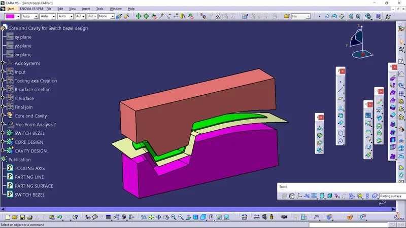
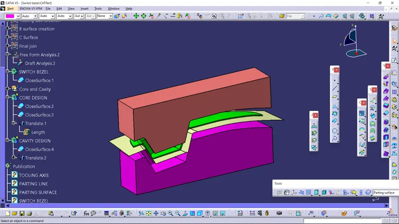
- Screenshots of the Draft analysis report for both the switch bezel plastic component
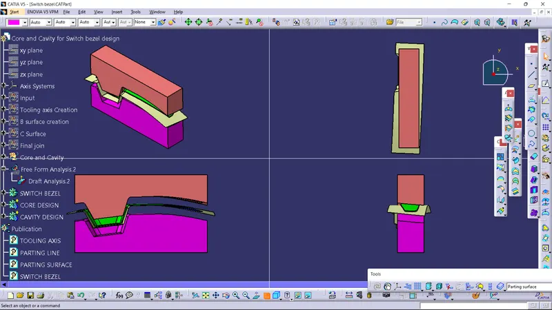
- Screenshots of the core and cavity blocks in various orientations (Isometric, Front, Side, and Top View)
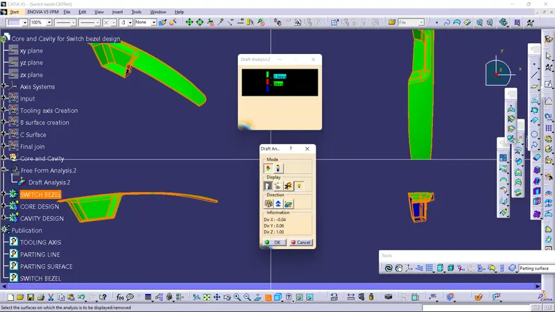
- Report
- A detailed report should be done explaining the draft analysis and the tooling axis creation.
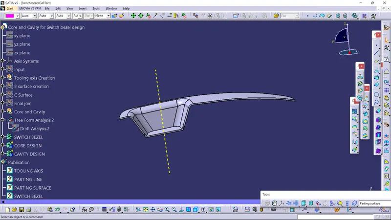
Draft angle is taken to be not more than 3 deg,here draft analysis option is chosen from analysis dialog box->Draft analysis.The draft analysis is performed on the entire model once its has closesurface.When the draft analysis is done by placing the compass on the tooling axis and lock it,select the model,few areas were exceeding the desired result so colour showed red instead of green,therefore to resolve that issue the draft angle is changed from 3 Deg to 2.9 Deg for the below model.The lower portion of the model is shown in blue which is acceptable as its on the reverse direction.
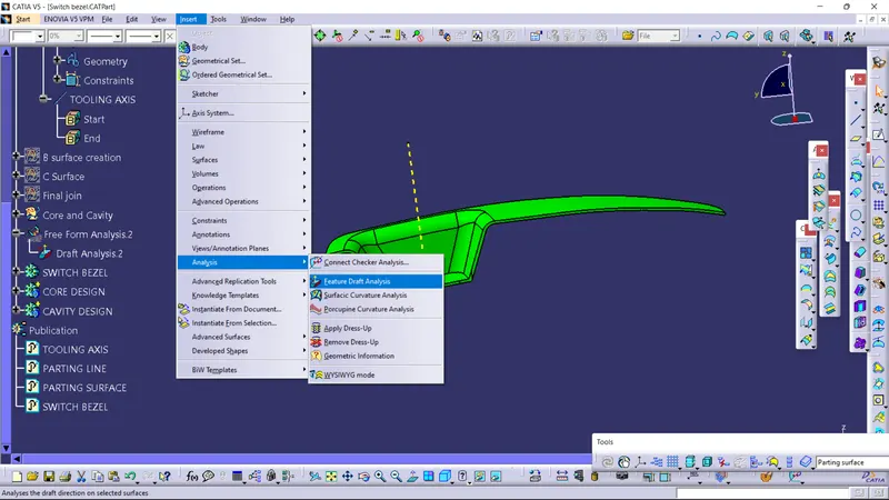
Tooling axis direction for this model is chosen to be on the Z axis.To create the tooling axis ,we used a different method instead of line option that is line is drawn using Position sketch method.
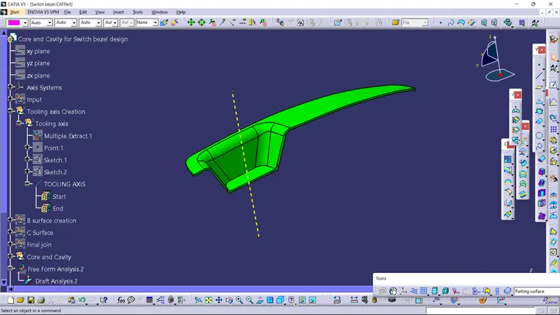
- An explanation should be given on the way of creating the tooling axis particularly the Bisecting method.
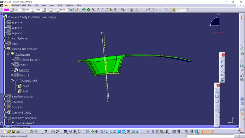
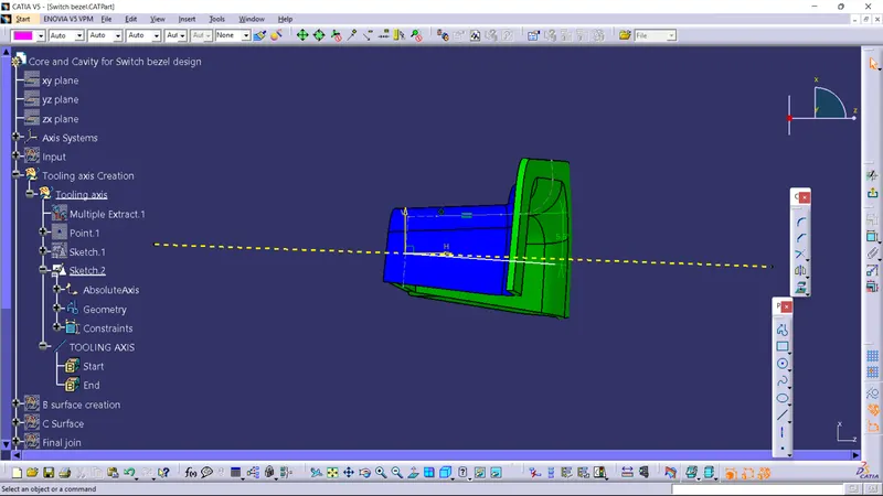
To create the tooling axis,Axis system is used and on the sketch, YZ plane and a point is selected for position sketch and by intersecting the class A surface,we have a construction line of class A surface for reference and by bisecting the lines we get a line along YZ plane and the same is done for the XZ plane but we use intersection command on the class A so we have no surface for reference along the x direction so we assume the angle to be 3 deg along the x axis(horizontal) line from Z axis line and by that we get a line along XZ plane at an angle of 3 Deg.Once both the line along YZ plane and XZ plane is created,bisecting those lines,we get the line which is the TOOLING AXIS.Later when the draft analysis is done we get few error due to the assumed 3 deg value so resolve that we change the angle by trial and error method and finally 5.5 deg value is given which gets the model cleared for draft analysis.
NOTE:The CATpart of the core and cavity blocks for the switch bezel is submitted as an attachment below in a ZIP file format.
THANKYOU