Week 8 - Challenge 1 - Draft Analysis on a Fan Cover
Fan cover model meeting the requirements of the draft angle and perform the Draft analysis on the model.
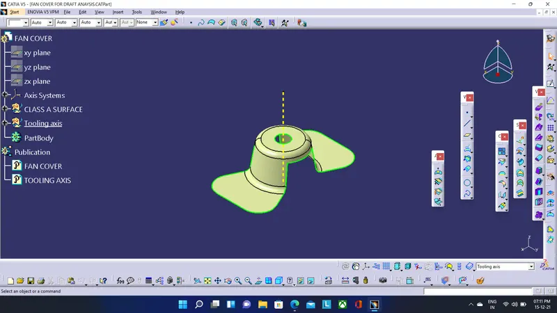
Image of the complete Draft analysis and Images of the color scale variant
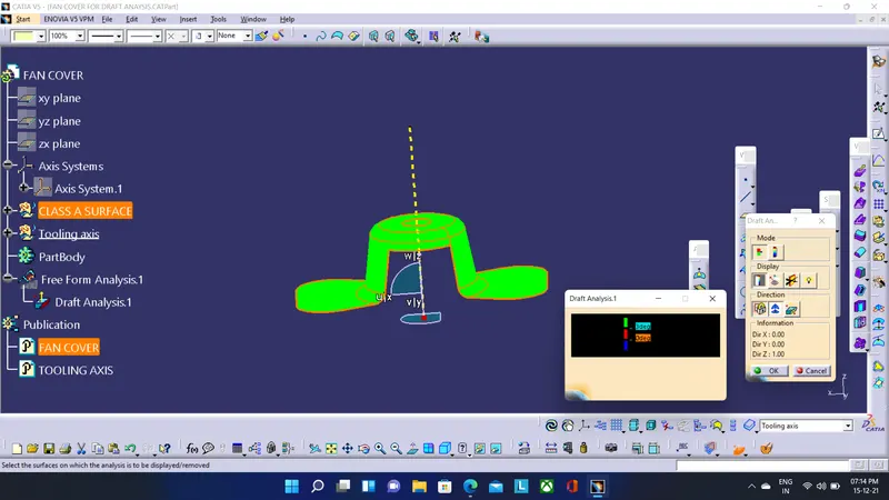
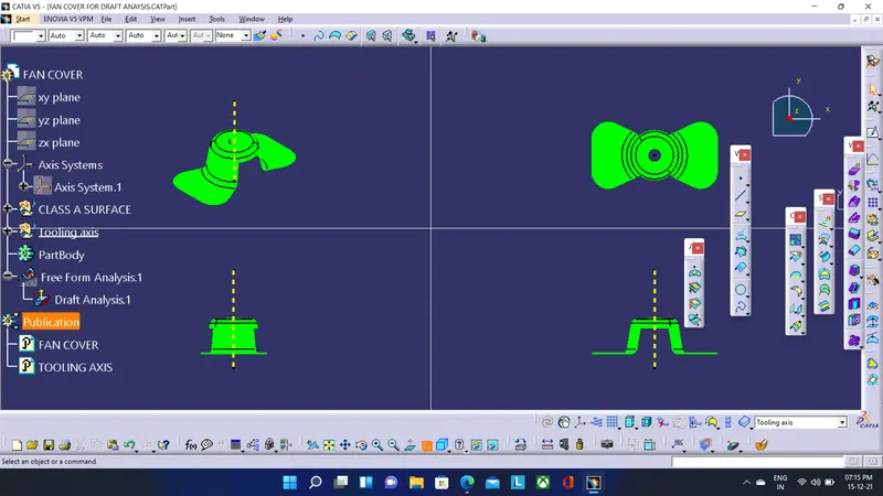
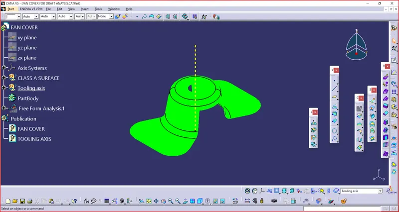
The model with the proper color code of the draft angle in various orientations (Isometric, Front, Side, and Top View)
REPORT:
- A detailed report should be done explaining the draft analysis and the tooling axis creation.
Draft is an angle given to a part having a permissable limit of 0.5 deg to 3 deg for part model which help in removal of the plastic part from the mold with the help of ejectors and the analysis is done on a part to ensure that there is no gap between surfaces.
Draft analysis:
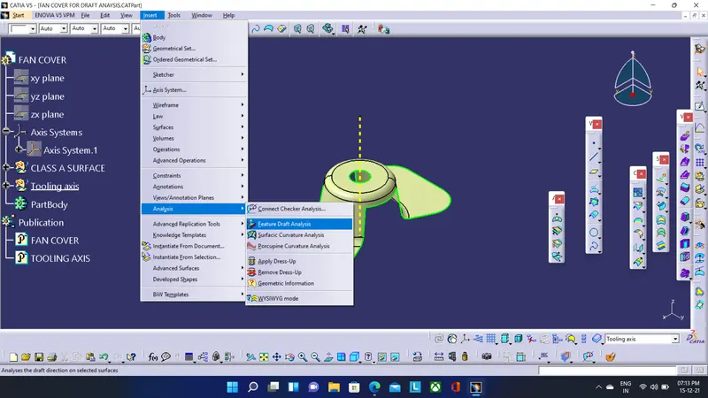
DESIGN CHECK 1: Change the option to material type from custom option below to avoid error during draft analysis.Use join option or boundary option then spilt boundary command to check for gaps.
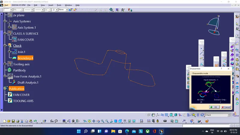
If nothing found then the model is continuous,we can delete the above performed steps and go on to create the tooling axis for that specific part.
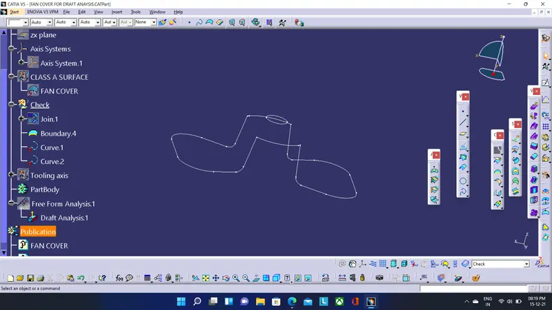
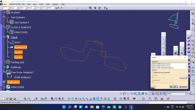
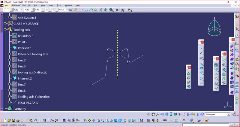
TOOLING AXIS and its CREATION: It is the direction in which mold (for plastic part) i.e Core and Cavity opens.It is performed to check the continuty of Class A or quality of Class A.To create tooling axis use bisecting command for creating a line and bisect X direction,Y direction line for the above part model.Change the colour to any of the given option under graphic properties (except Green,Blue,Red) and line sizing to identify the tooling axis during draft analysis.
- An explanation should be given on the way of creating the tooling axis particularly the Bisecting method.
Insert a new geometrical set, use boundary option and keep point. Insert axis system on the point.
FOR X DIRECTION TOOLING AXIS: Create a reference axis along Z axis.Use XZ PLANE from axis plane in boundary option and create line using points on that plane, once the line is created create a line using bisecting command and choose the line created,as a result bisecting line will be formed along X direction.
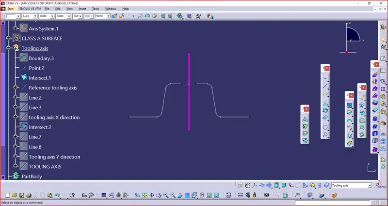
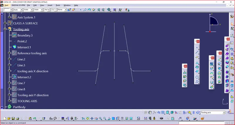
FOR Y DIRECTION TOOLING AXIS:Use YZ PLANE from axis plane in boundary option and create line using points on that plane, once the line is created create a line using bisecting command and choose the line created,as a result bisecting line will be formed along X direction.
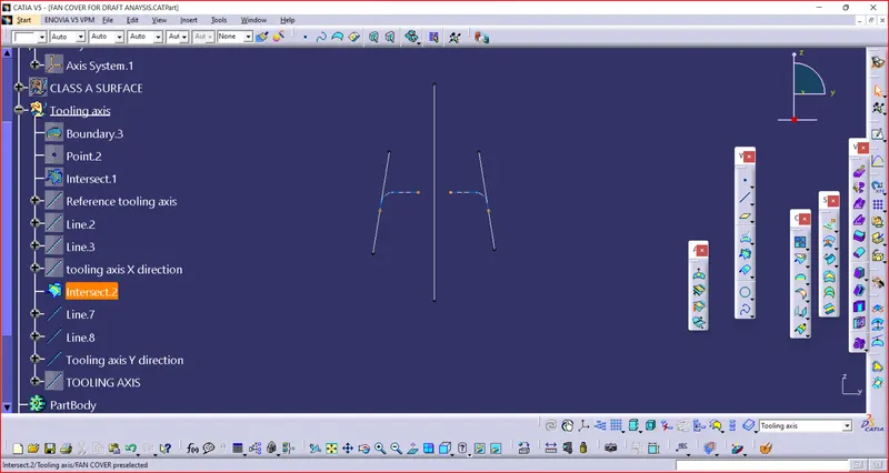
TOOLING AXIS:Create a line using bisecting command and choose the tooling axis X Direction and the tooling axis Y Direction from the tree structure keeping them hiden to avoid error,as a result bisecting line will be formed for the part model along Z Axis as per our best suited option.`
The final fan cover model after draft analysis.
Note:The CATpart has been submitted as an attachment in Zip folder file.
Thankyou.