Week 11 - Final project
Objective:
To create a CAD Model using CLASS A, Nominal Thickness and Attachement Strategy.
Procedure:
Step-1:
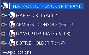
- The Reference part of the Door Trim consists of four parts.
- Arm Rest Console
- Lower Substrate
- Map Pocket
- Bottle Holder.
Step-2:
- Convert the Reference part into individual parts respectively.
- After converting into individual parts asssemble all the parts together into a Single Assembly product and save it as Final Project - Door Trim Panel.
Step-3:
Lower Substrate: ( Class A+Class B+Class C Creation)
Objective:
- In the Lower Substrate part, from the given Class A surface we should create thickened part using master section as reference.
- Create Tooling Axis for Lower Substrate.
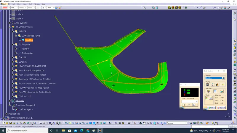
- Check draft on Class A after tooling axis creation.
Draft Analysis on Lower Substrate Class-A:
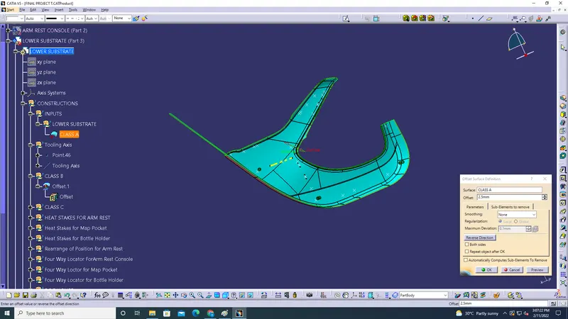
- Create Class B surface by offset the Class A with 2.5 mm. By checking with the master section. Class B Surface is in Sky Blue color
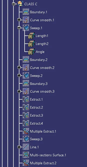
- Create Class C surface by selecting the boundary with limit-1 and limit-2 .
- Use smooth curve with curvature.
- Sweep Subtype as With Reference Surface - Select the guide curve - Reference surface as Class A- Angle 90 degree - Length 20 mm.
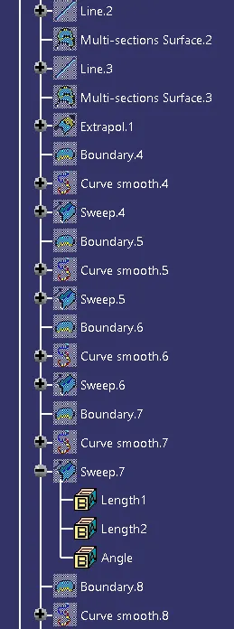
- Certain missing Region is closed by Spline-Extract- Multi layer surface.
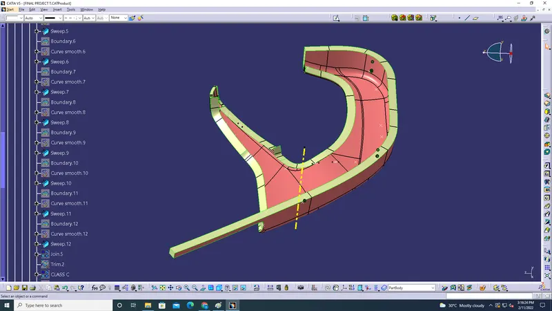
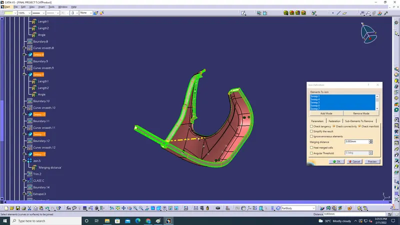
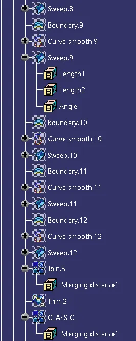
- All the sweeps & Multisurface is joined by using Join Command with 0.003mm merging distance.
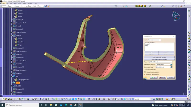
- Trim command is used to remove the extra regions to produce a perect continous Class C region.
- Now Join command is used to Join the Class A and Class C surface.
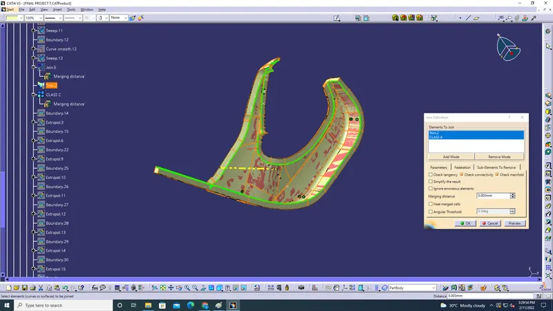
- Now as The Class A & Class C has been joined.
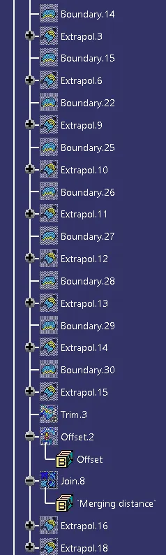
- The Class B is not getting extend on to the Class C surface. So we have to use Boundary and Extrapole the outer regions of Class B.
- After Extrapole the regions, has to be joined and trim with the Class A & Class C surface.
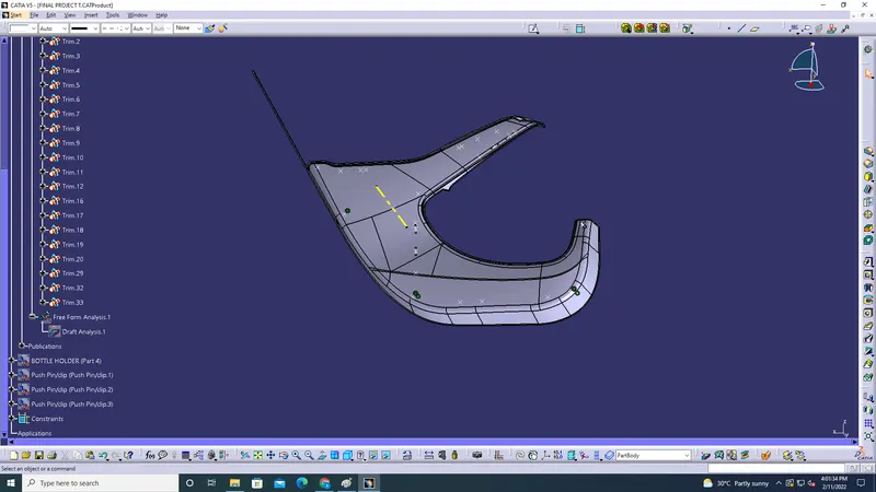
The below image is the Joined Class A+B+C of Lower Substrate
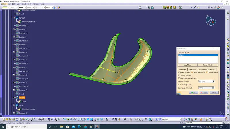
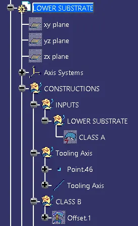
Tree Structure for Lower Substrate with Inputs- Class A- Class B- Class C
- Convert the surface into a soild body by using Part Work bench - Closed Surface.
Map Pocket: ( Class A+Class B+Class C Creation)
Objective:
- In the Map Pocket part, from the given Class A surface we should create thickened part using master section as reference.
- Create Tooling Axis for Lower Substrate.
- Check draft on Class A after tooling axis creation.
Draft Analysis on the Map Pocket Class A surface:
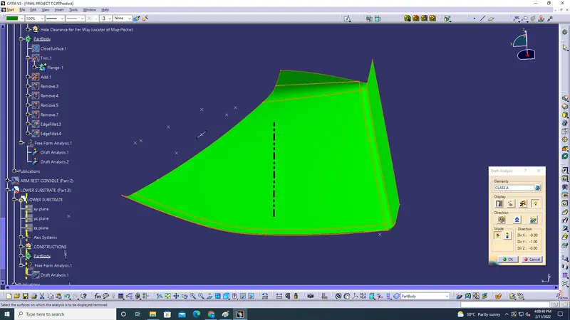
- The Class A surface is offset to 2.5 mm.
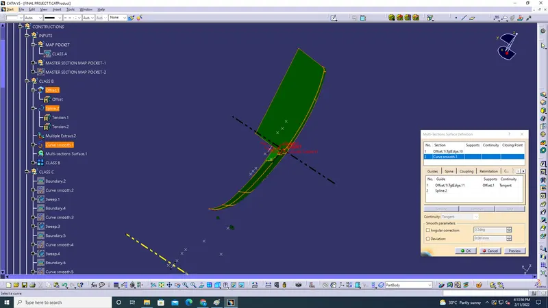
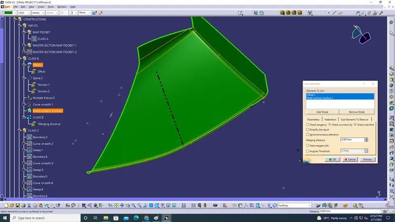
- There is small portion which is not coverd fully we have to use Spline-Extract-Muti Section surface to cover the missing portion.
Multi-Section is used to cover the missing portion:
Join Command is used to get the fully coverd Class B surface:
- Create Class C surface by selecting the boundary with limit-1 and limit-2 .
- Use smooth curve with curvature.
- Sweep Subtype as With Reference Surface - Select the guide curve - Reference surface as Class A- Angle 90 degree - Length 20 mm.
- Certain missing Region is closed by Spline-Extract- Multi layer surface.
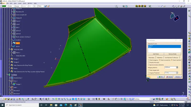
- Convert the surface into a soild body by using Part Work bench - Closed Surface.
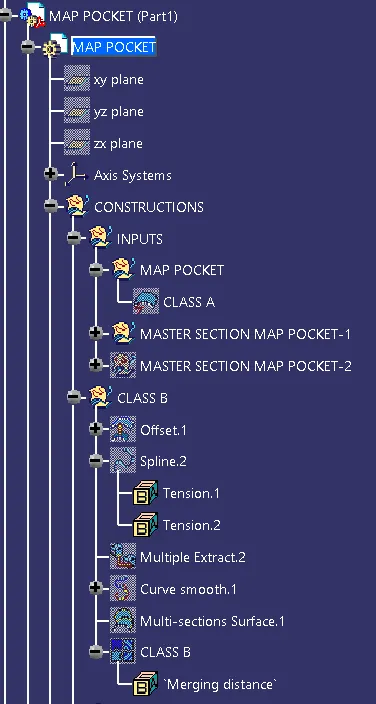
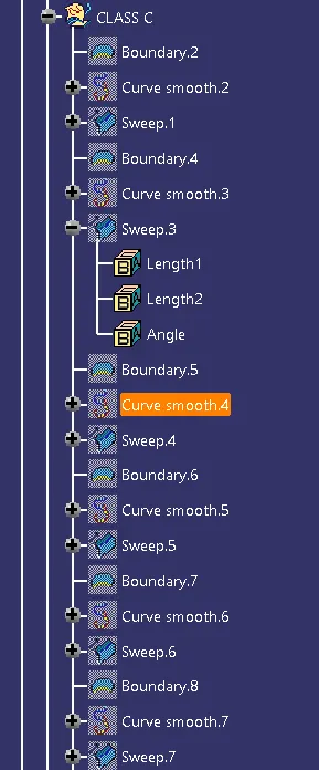
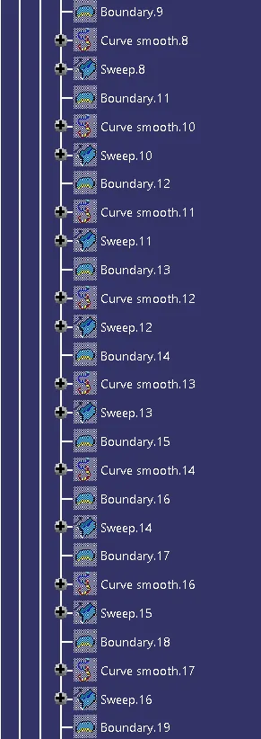
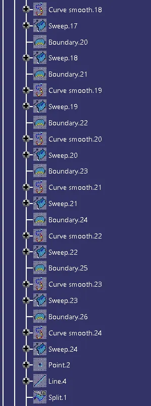
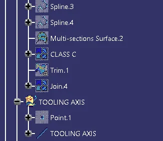
Tree Structure of Map Pocket:
Bottle Holder: ( Class A+Class B+Class C Creation)
Objective:
- In the Bottle Holder part, from the given Class A surface we should create thickened part using master section as reference.
- Create Tooling Axis for Lower Substrate.
- Check draft on Class A after tooling axis creation.
Draft Analysis on Bottle Holder for Class A Surface:
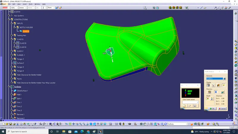
- The Class A surface is offset to 2.5 mm to create the Class B surface.
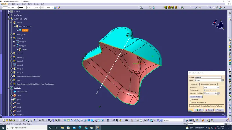
- Create Class C surface by selecting the boundary with limit-1 and limit-2 .
- Use smooth curve with curvature.
- Sweep Subtype as With Reference Surface - Select the guide curve - Reference surface as Class A- Angle 90 degree - Length 20 mm.
Join Command is used to Join all the sweep:
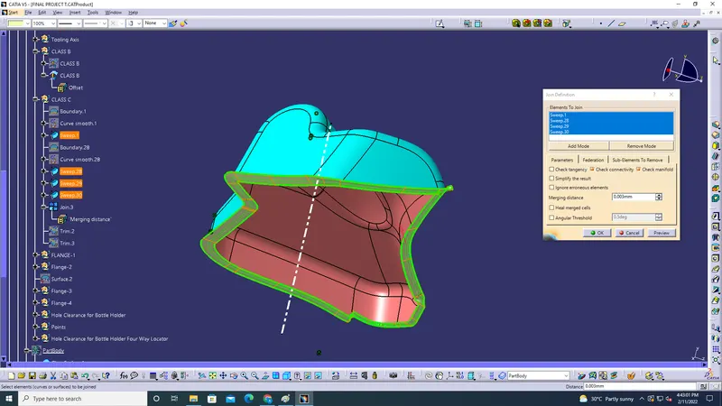
- Trim Command is Used to Join the Class A+ Class C Surface:
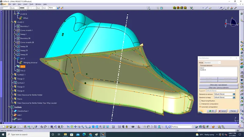
- Trim Command is Used to Join the (Class A+ Class C) & Class B Surface:
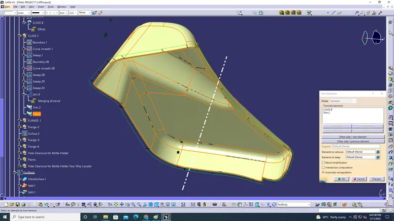
- The closed Class A+B+C is converted into a soild part by using closed surface from Part Workbench
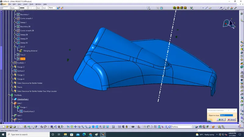
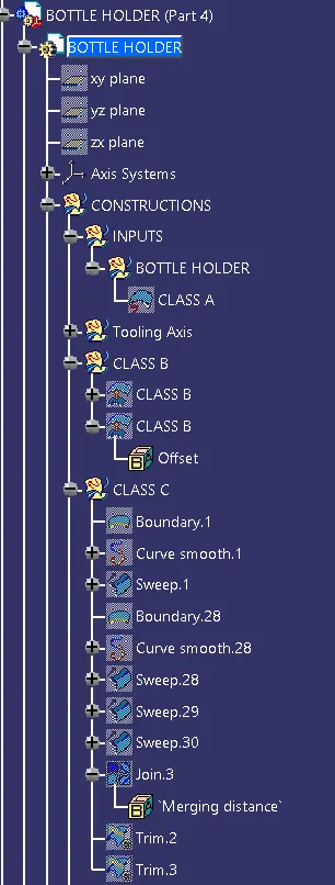
Tree Structure of Bottle Holder:
Arm Rest Console: ( Class A+Class B+Class C Creation)
Objective:
- In the Arm Rest Console part, from the given Class A surface we should create thickened part using master section as reference.
- Create Tooling Axis for Lower Substrate.
- Check draft on Class A after tooling axis creation.
Draft Analysis on Arm Rest Console for Class A Surface:
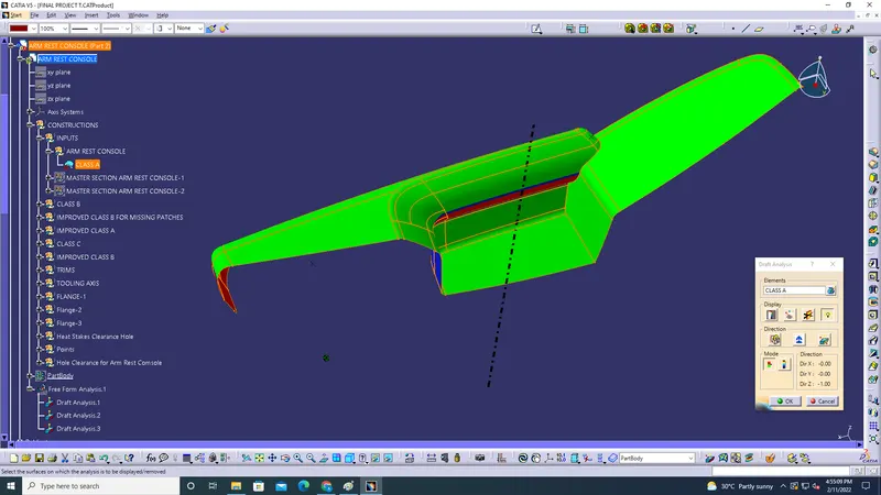
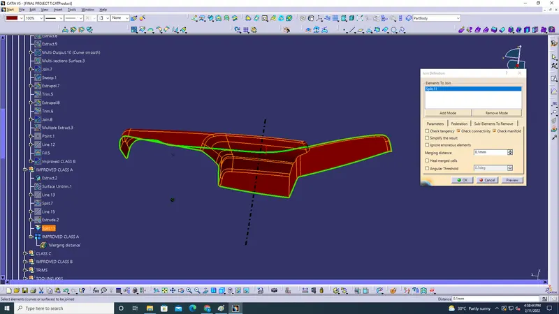
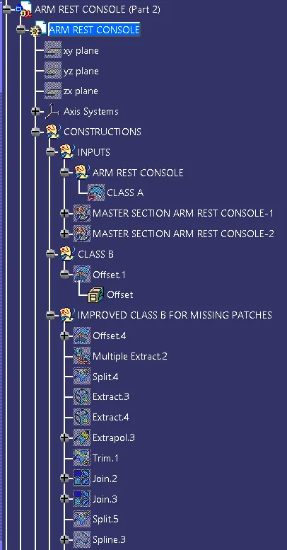
- Improvement is done on the Class A due to some missing portions and boundary overlap.
- The improved Class A after using Extract - Split-Extrude-Join
- After improvement of Class A then it is Offset to 2.5 mm to form Class B surface.
- After Offset of Class A to 2.5mm there are still more patches which is not fully closed as shown below.
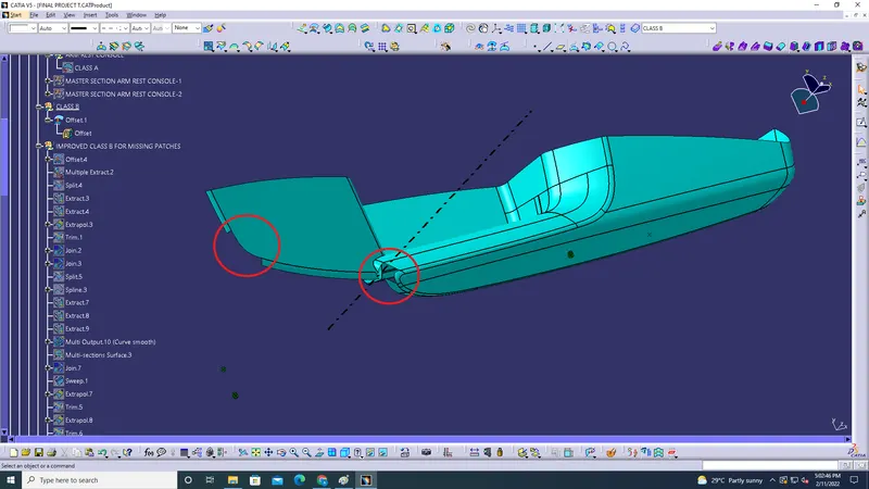
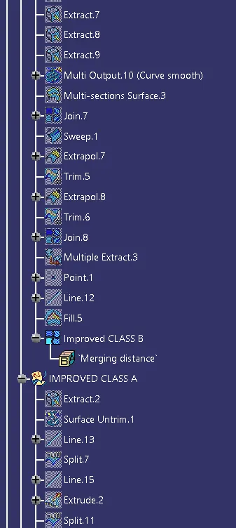
- The Improvement on Class B is done by using Mutiple Extract, Spline, Muti-section,Split,Trim & Join.
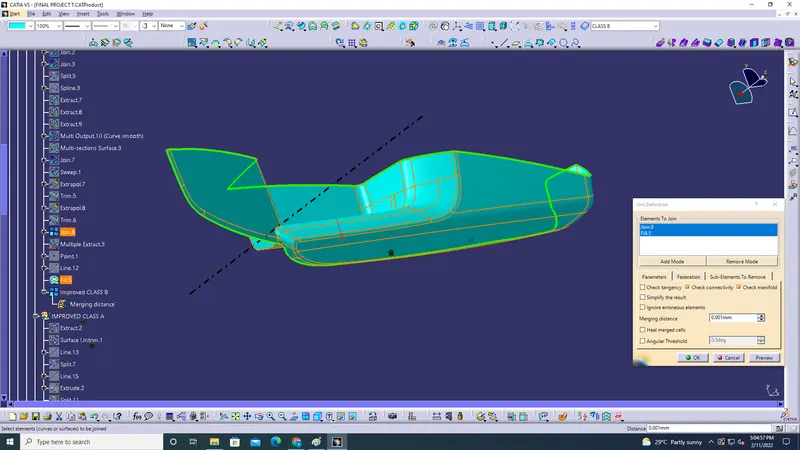
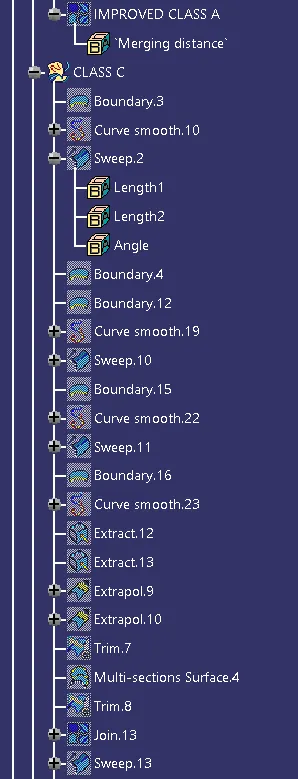
- Create Class C surface by selecting the boundary with limit-1 and limit-2 .
- Use smooth curve with curvature.
- Sweep Subtype as With Reference Surface - Select the guide curve - Reference surface as Class A- Angle 90 degree - Length 20 mm.
- Join command is used to join the Sweep of Class C surface along with Class A surface.
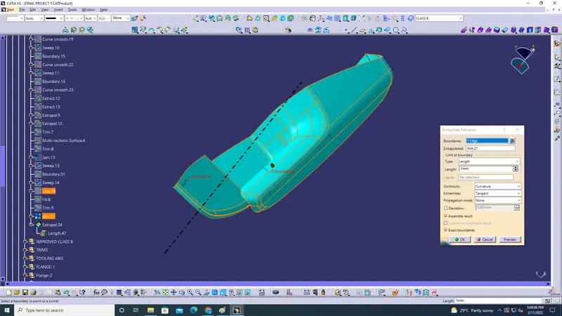
- After joining the Class A+Class C.
- The Class B surface is extrapolate along with the Class C.
- Final Trim is used to Join the Class A+ Class B+ Class C.
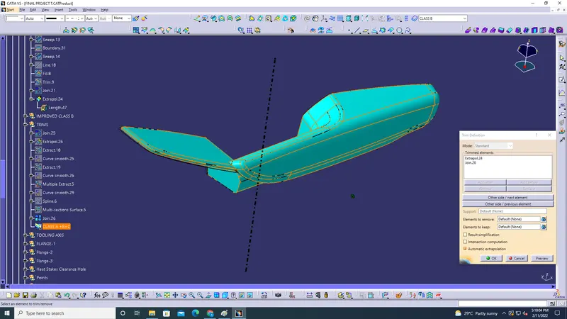
- The Class A+B+C is coverted into a solid body by using part work brnch closed surface command.
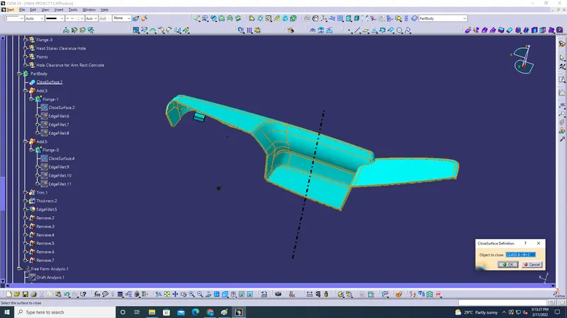
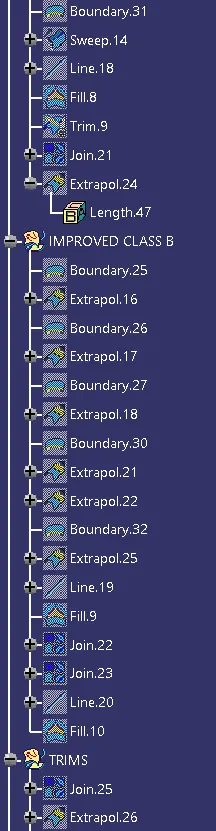
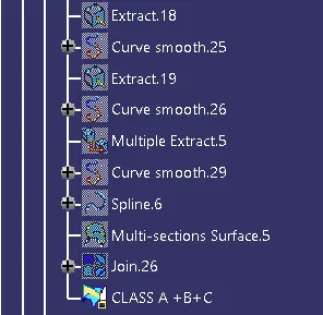
Tree Structure of Arm Rest Console:
Flange Creation:
Arm Rest Console:
- In Arm Rest Console there are 3 Flange created.
- The Flange is mainly used to hold the B side attachement features.
- The Flange dimensions are defines as per the Master Sections given as input.
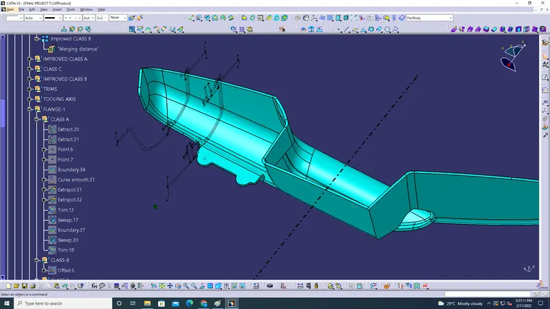
Flange-1:
- It is created by extract the line from the Master-Section.
- Extrapole the lines
- Trim the lines.
- Create a boundary on class A for a specific distance by giving points.
- Sweep Subtype as With Reference Surface - Select the guide curve - Reference surface - Angle 90 degree - Length 20 mm.
- After Sweep the created surface is Class A
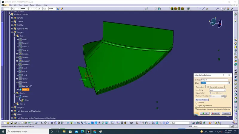
- Offset the Class A to 2.5mm to create Class B.
- Class C is created by drawing Sketch of required length.
- Extrapole the sketch and trim the Class A+Class B+Class C.
- To close the backside gap use sweep with reference and extrapole with the main part.
- The created part is converted into a soild part by using Closed Surface.
- The Flange-1 Boady is ADD with boolean operation with the main Part Body.
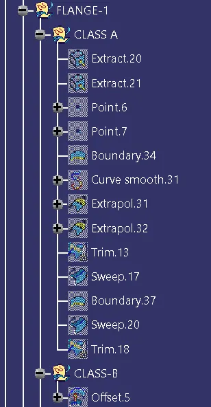
Tree Structure of Flange-1 of Arm Rest Console:
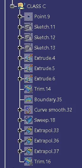
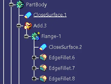
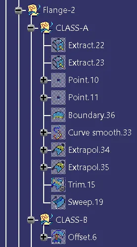
Flange-2:
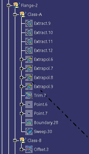
- It is created by extract the line from the Master-Section.
- Extrapole the lines
- Trim the lines.
- Create a boundary on class A for a specific distance by giving points.
- Sweep Subtype as With Reference Surface - Select the guide curve - Reference surface - Angle 90 degree - Length 20 mm.
- After Sweep the created surface is Class A
- Offset the Class A to 2.5mm to create Class B.
- Class C is created by drawing Sketch of required length.
- Extrapole the sketch and trim the Class A+Class B+Class C.
- To close the backside gap use sweep with reference and extrapole with the main part.
- The created part is converted into a soild part by using Closed Surface.
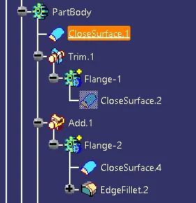
- The Flange-1 Boady is ADD with boolean operation with the main Part Body.
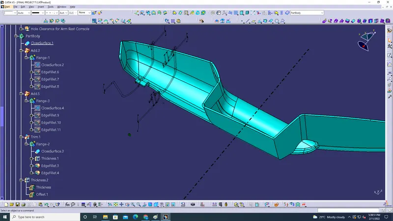
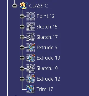
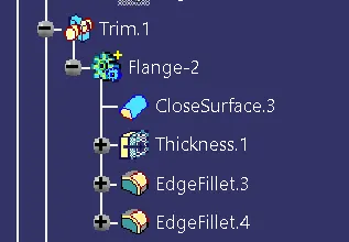
Tree Structure of Arm Rest Console Flange-2:
Flange-3:
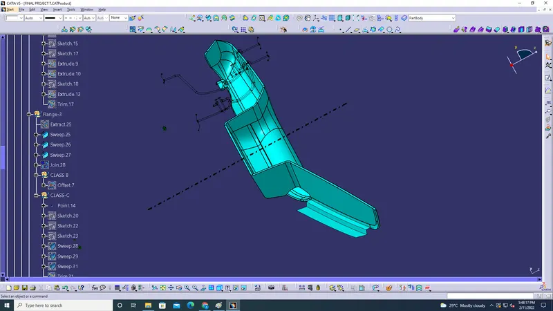
- This Flange is created on our own by considering as there is no attachment on one end.
- This is obtained by Extact - Sweep- Join. (This gives the Class A)
- The Class B is created by offset to 2.5mm.
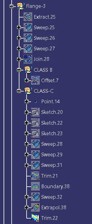
- The Class C is created by drawing sketch- Sweep-Trim
The Joinned surface to create Class A surface:
Class B Surface:
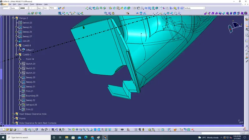
Class A+ B+C:
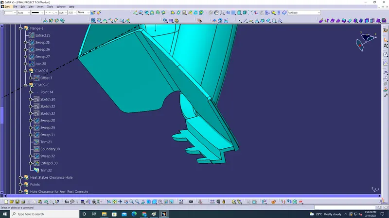
Tree Structure of Arm Rest Flange-3:
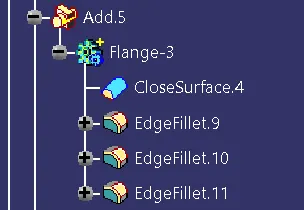
Map Pocket:
- In Map Pocket there are 2 Flange creation.
- The Flange is mainly used to hold the B side attachement features.
- The Flange dimensions are defines as per the Master Sections given as input.
Flange-1:
- It is created by extract the line from the Master-Section.
- Extrapole the lines
- Trim the lines.
- Create a boundary on class A for a specific distance by giving points.
- Sweep Subtype as With Reference Surface - Select the guide curve - Reference surface - Angle 90 degree - Length 20 mm.
- After Sweep the created surface is Class A
- Offset the Class A to 2.5mm to create Class B.
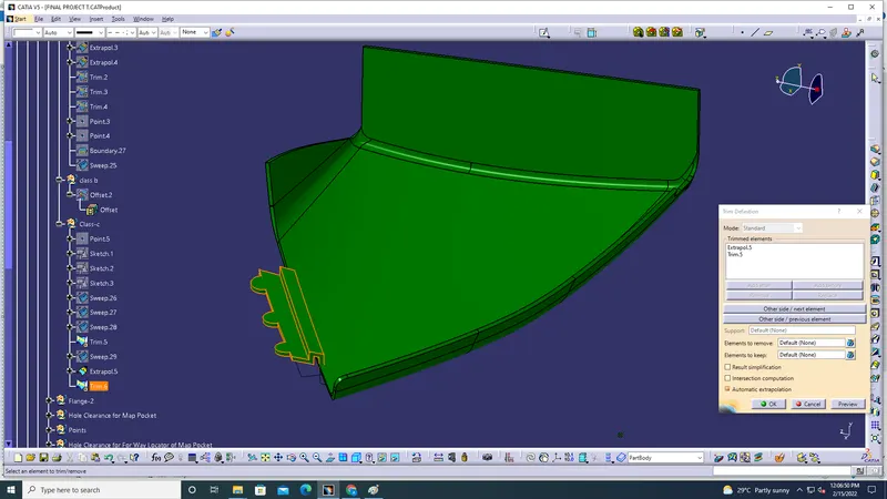
- Class C is created by drawing Sketch of required length.
- Extrapole the sketch and trim the Class A+Class B+Class C.
- To close the backside gap use sweep with reference and extrapole with the main part.
- The created part is converted into a soild part by using Closed Surface.
- The Flange-1 Boady is TRIM with boolean operation with the main Part Body.
Class A creation for Flange-1:
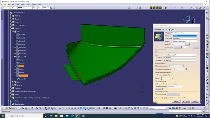
Class B creation of Flange-1:
Class C Creation:
- The CLASS C creation is by drawn by sketch for specific limits.
- Then sweep command is used to extend the drawn sketcks
- Trim command is used to remove unwanted surfaces.
- The surface back is closed by performing another sweep with the Class A surface.
- TRIM command is used to create a solid CLASS A+B+C
- The Closed body is create into a solid body by part workbench Closed Surface.
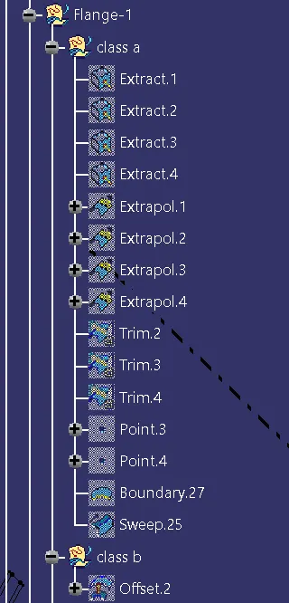
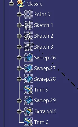
Tree Structure of Flange-1:
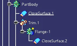
Flange 2 Creation of MAP Pocket:
Class A of Flange-2:
- Extract the lines from the master section -2 of Map Pocket.
- Trim the extrapolated lines.
- Create 2 points on the Class A with boundary.
- Sweep the extrapolated line to fromm the Class A of Flange-2.
Class A of Flange-2:
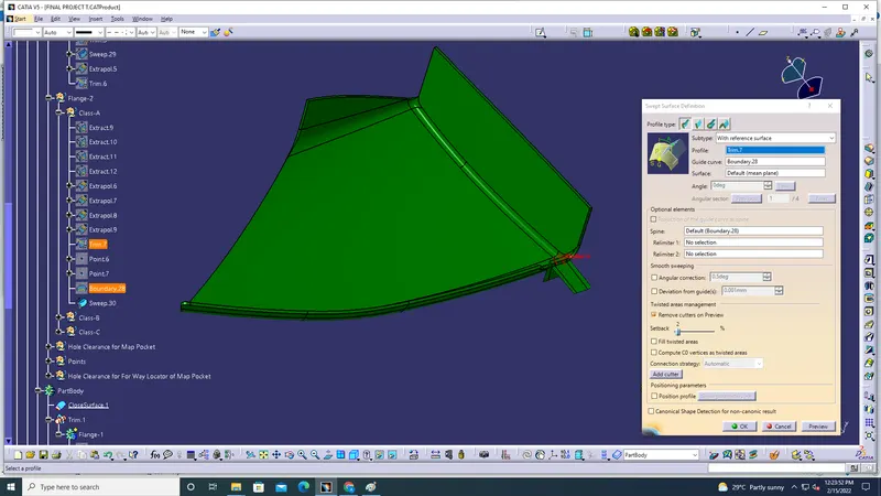
Class B of Flange-2:
- Offset Class A to 2.5 mm.
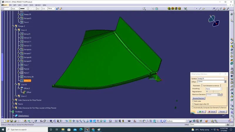
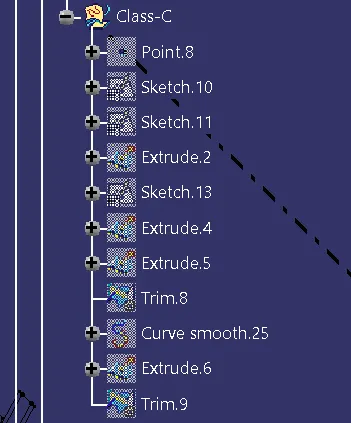
Class C of Flange-2:
- The CLASS C creation is by drawn by sketch for specific limits.
- Then sweep command is used to extend the drawn sketcks
- Trim command is used to remove unwanted surfaces.
- The surface back is closed by performing another sweep with the Class A surface.
- TRIM command is used to create a solid CLASS A+B+C
- The Closed body is create into a solid body by part workbench Closed Surface.
Sketch for creation of Class C of Flange-2:
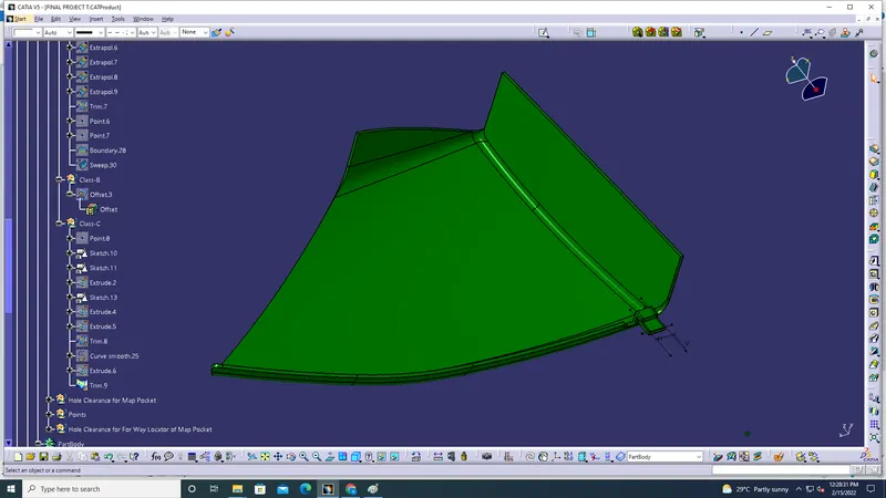
Trim command used on Class C of Flange-2 to create into soild body:
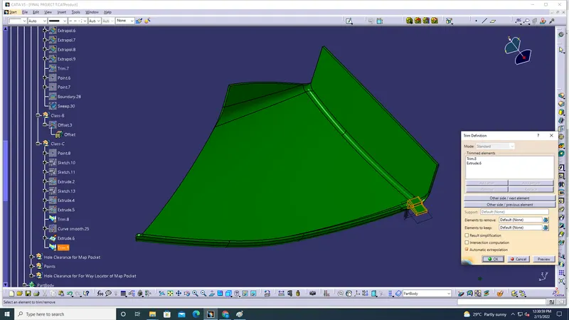
Tree Structure of Flange-2 of Map Pocket:
Bottle Holder:
- In Bottle Holder there are 4 Flange creation.
- The Flange is mainly used to hold the B side attachement features.
- The Flange dimensions are defines as per the Master Sections given as input.
Flange-1:
Class-A:
- Two points are created on the Class A surface.
- Then boundary is taken on Class A with limit element between the two points.
- Smooth curve is used to remove the vertex from the boundary.
- Sweep is used to form the flanges.
- Join the created sweep to from the Class A Surface.
Class A of Flange-1:
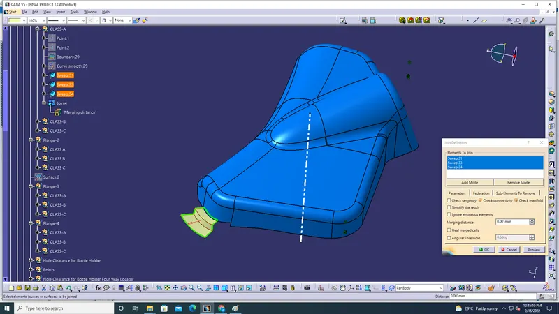
Class B of Flange-1:
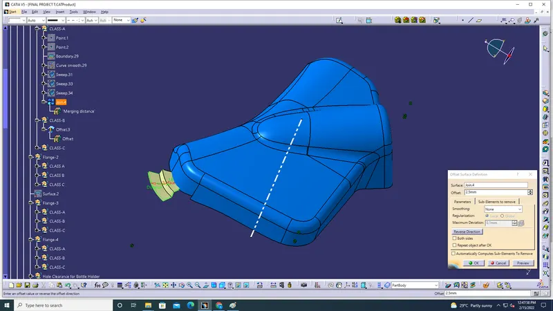
Class C of Flange-1:
- The CLASS C creation is by drawn by sketch for specific limits.
- Then sweep command is used to extend the drawn sketcks
- Trim command is used to remove unwanted surfaces.
- The surface back is closed by performing another sweep with the Class A surface.
- TRIM command is used to create a solid CLASS A+B+C
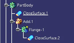
- The Closed body is create into a solid body by part workbench Closed Surface.
Sketch for creation of Class C of Flange-1:
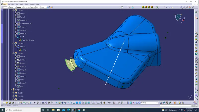
Trim command used on Class C of Flange-1 to create into soild body:
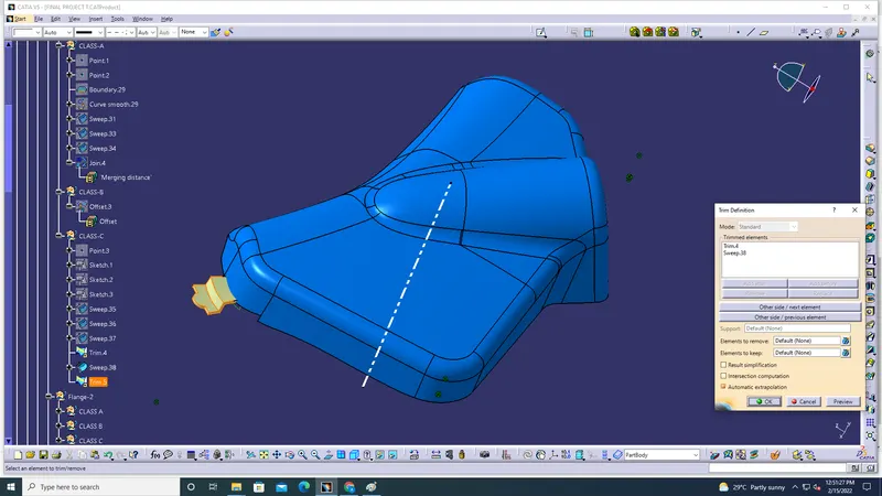
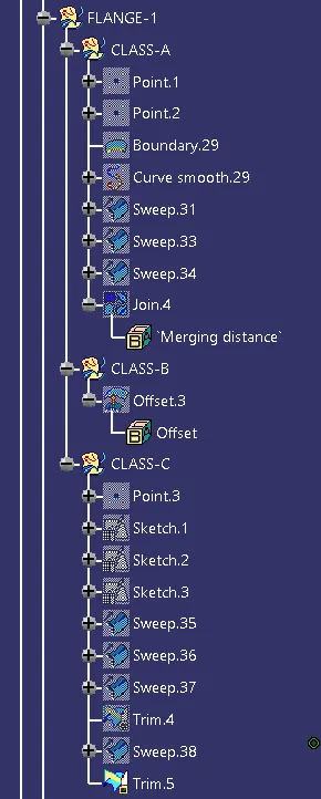
Tree Structure of Flange-1:
Flange-2:
Class-A:
- Two points are created on the Class A surface.
- Then boundary is taken on Class A with limit element between the two points.
- Smooth curve is used to remove the vertex from the boundary.
- Sweep is used to form the flanges.
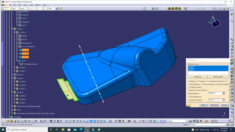
- Join the created sweep to from the Class A Surface.
Class A of Flange-2:
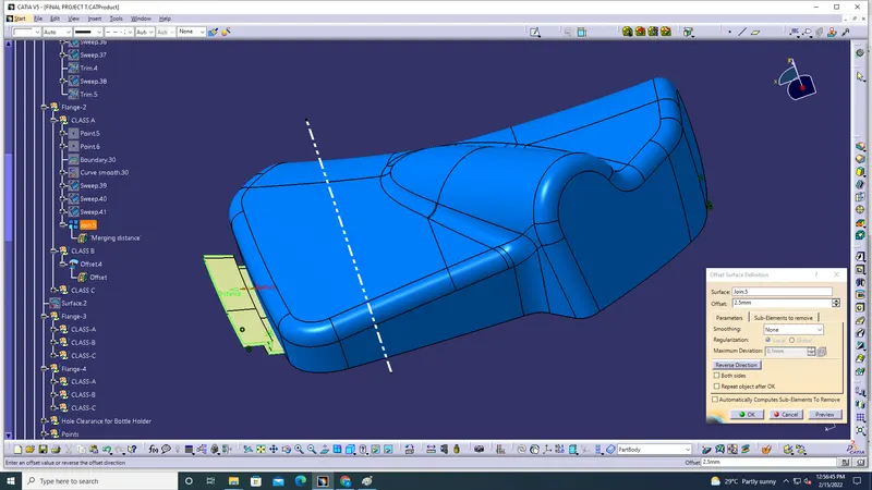
Class B of Flange-2:
Class C of Flange-2:
- The CLASS C creation is by drawn by sketch for specific limits.
- Then sweep command is used to extend the drawn sketcks
- Trim command is used to remove unwanted surfaces.
- The surface back is closed by performing another sweep with the Class A surface.
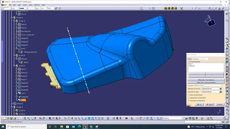
- TRIM command is used to create a solid CLASS A+B+C
- The Closed body is create into a solid body by part workbench Closed Surface.
Sketch for creation of Class C of Flange-2:
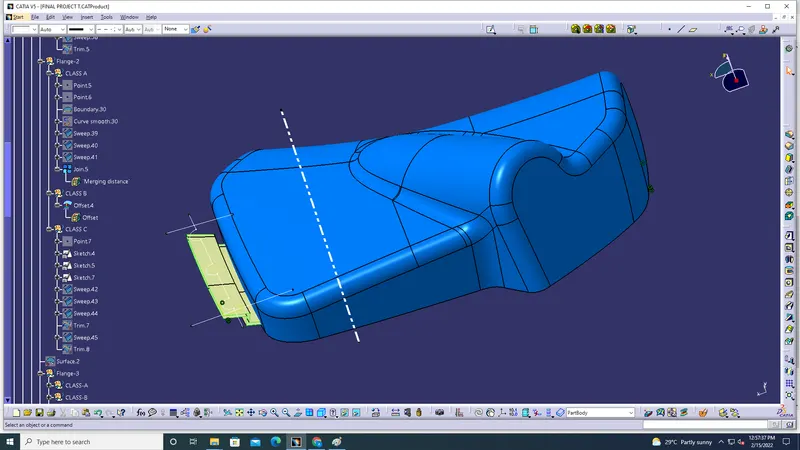
Trim command used on Class C of Flange-2 to create into soild body:
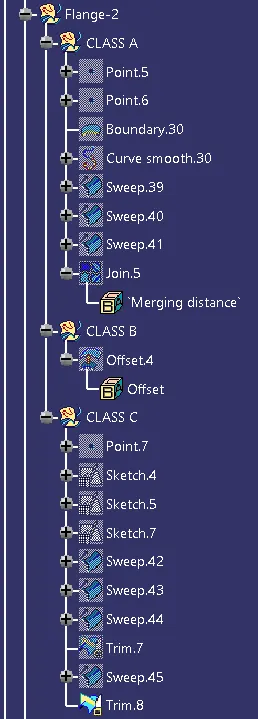
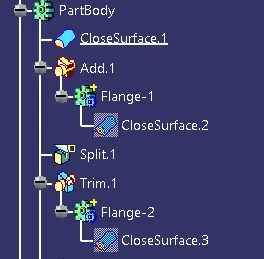
Tree Structure of Flange-2:
Flange-3:
Class-A:
- Two points are created on the Class A surface.
- Then boundary is taken on Class A with limit element between the two points.
- Smooth curve is used to remove the vertex from the boundary.
- Sweep is used to form the flanges.
- Join the created sweep to from the Class A Surface.
Class A of Flange-3:
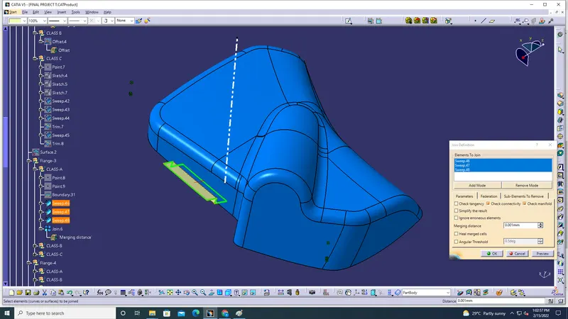
Class B of Flange-3:
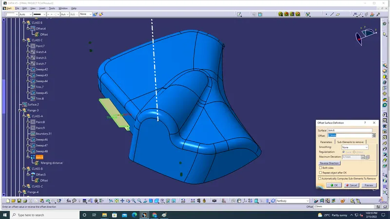
Class C of Flange-3:
- The CLASS C creation is by drawn by sketch for specific limits.
- Then sweep command is used to extend the drawn sketcks
- Trim command is used to remove unwanted surfaces.
- The surface back is closed by performing another sweep with the Class A surface.
- TRIM command is used to create a solid CLASS A+B+C
- The Closed body is create into a solid body by part workbench Closed Surface.
Sketch for creation of Class C of Flange-3:
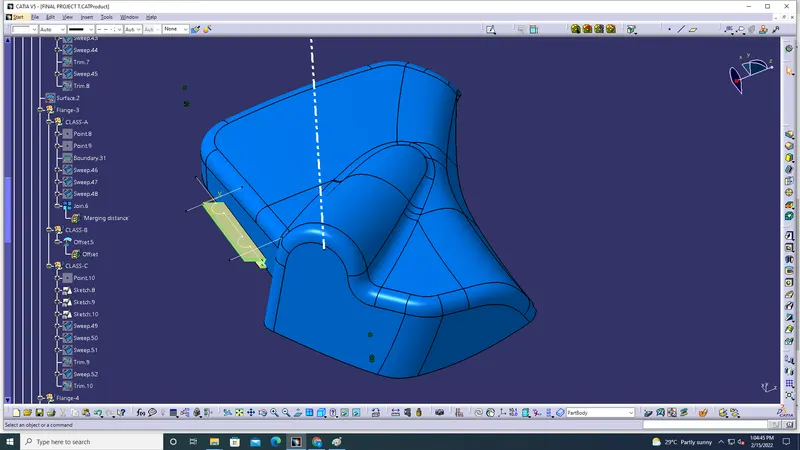
Trim command used on Class C of Flange-3 to create into soild body:
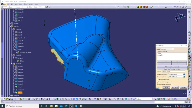
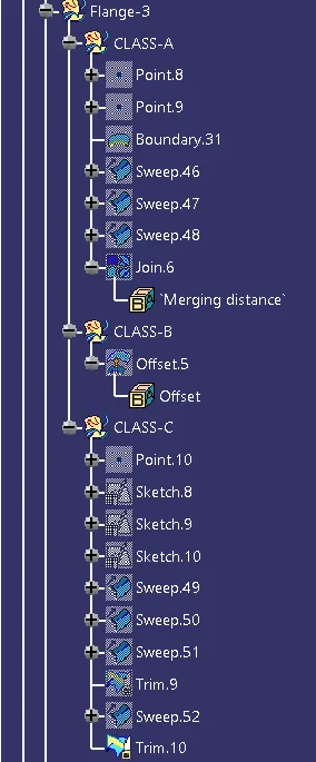
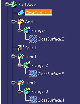
Tree Structure of Flange-3:
Flange-4:
Class-A:
- Two points are created on the Class A surface.
- Then boundary is taken on Class A with limit element between the two points.
- Smooth curve is used to remove the vertex from the boundary.
- Sweep is used to form the flanges.
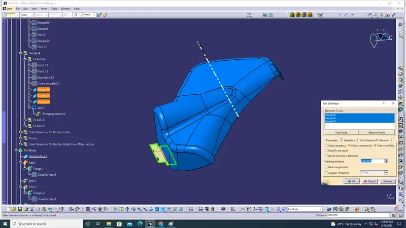
- Join the created sweep to from the Class A Surface.
Class A of Flange 4:
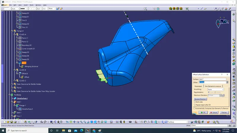
Class B of Flange-4:
Class C of Flange-4:
- The CLASS C creation is by drawn by sketch for specific limits.
- Then sweep command is used to extend the drawn sketcks
- Trim command is used to remove unwanted surfaces.
- The surface back is closed by performing another sweep with the Class A surface.
- TRIM command is used to create a solid CLASS A+B+C
- The Closed body is create into a solid body by part workbench Closed Surface.
Sketch for creation of Class C of Flange-4:
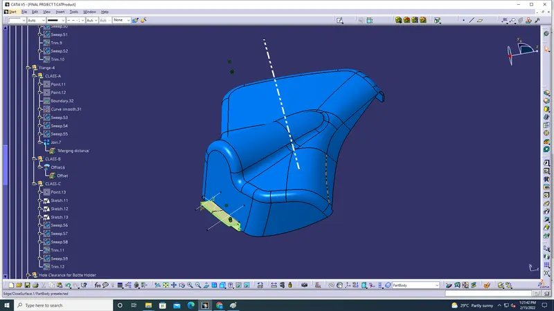
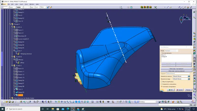
Trim command used on Class C of Flange-4 to create into soild body:
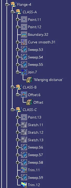
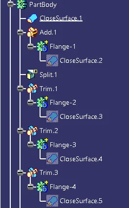
Tree Structure of Flange-4:
B-Side Attachment Features:
- The B-side attachement features consists of Heat Stakes,Four Way Locators,Dog House and Push Pins.
- Clearance Hole is given for Heat Stakes anf Four Way Locators.
Heat Stakes:
Heat Staking is a pulsed-heat process to join two or more parts out of which one atleast is made of plastic.
The process to deform the plastic material using heat and force at a set process time. The bond is made bt partially deforming the plastic part in order to the fix the other.
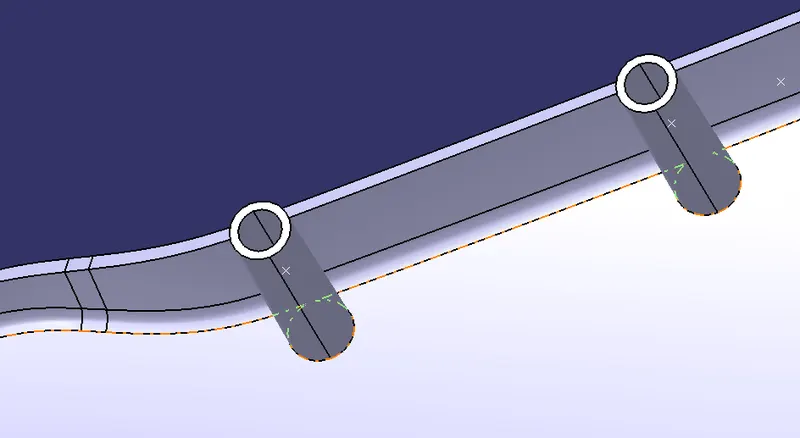
Heat Stakes on Lower Substrate:
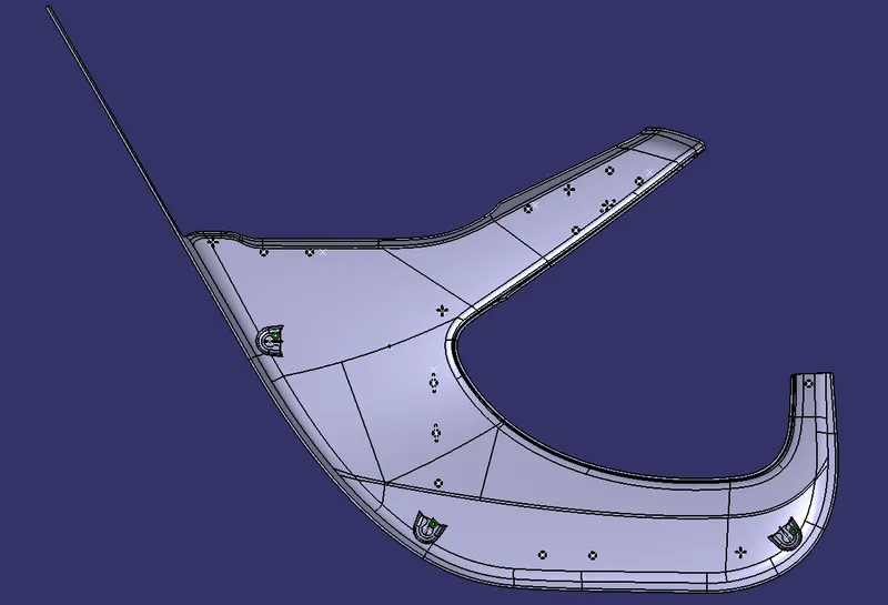
Dog House:
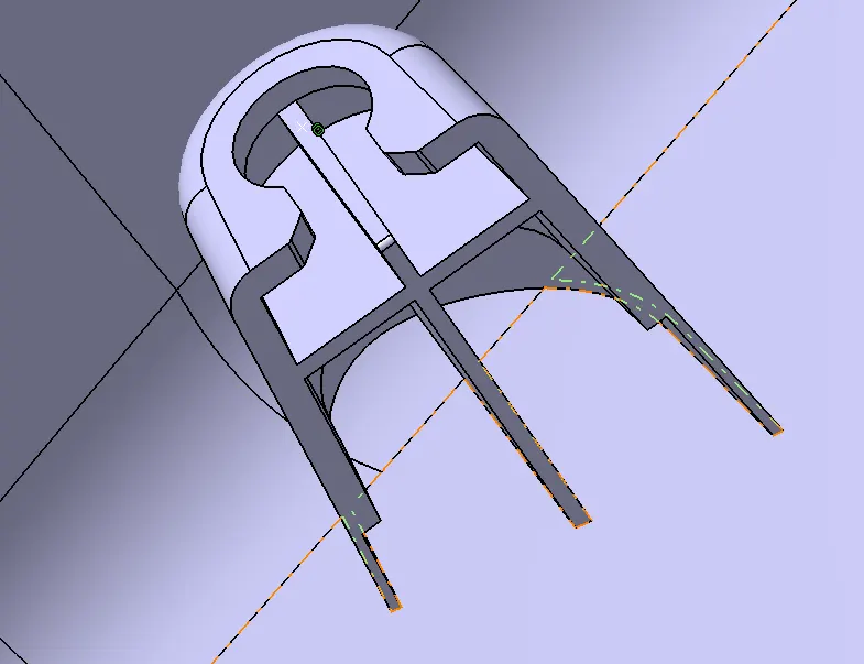
Create the Dog House as per the design rules and give the requiredd draft angle.
• Dog House wall thickness at intersecton of the part Wall(C) should be 40% or less than the main wall stock(T).
Height of (B) should be between 3-6 mm.
Dog house rule
B=4mm
t=2.5mm
C-0.4 * t-1mm
• Extract the sweep and offset to b=4mm and c-1mm on all directions like the below
Dog House:
DRAFT ANALYSIS:
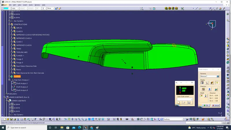
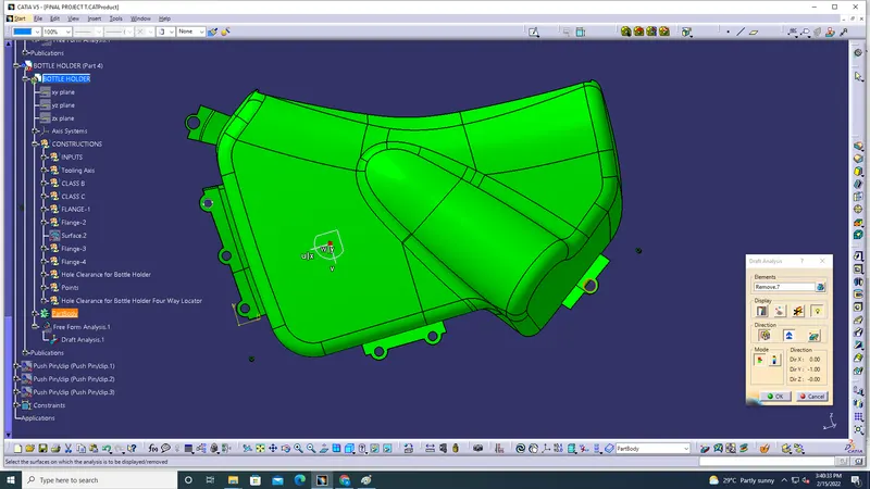
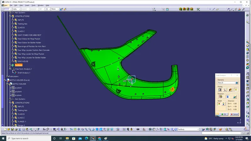
The draft analysis must be done on the component in order to check the draft angle provided for the coomponent. The advisable value for the draft angle is 0.53 deg which is the nominal value for the draft in plastic component, the draft analysis done on the component on the axis where the component is moulded.The drafts are vvery essential for the component manufacturing, the drafts are provided on all the engineering features.For textured faces the draft angle is 7 deg.
Tooling axis and side core axis are used for the draft analysis.
Draft Analysis of Map Pocket:
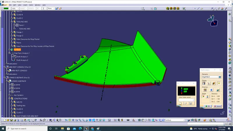
Draft Analysis of Arm Rest Console:
Draft Analysis of Bottle Holder:
Draft Analysis of Lower Substrate:
Final Images:
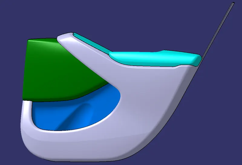
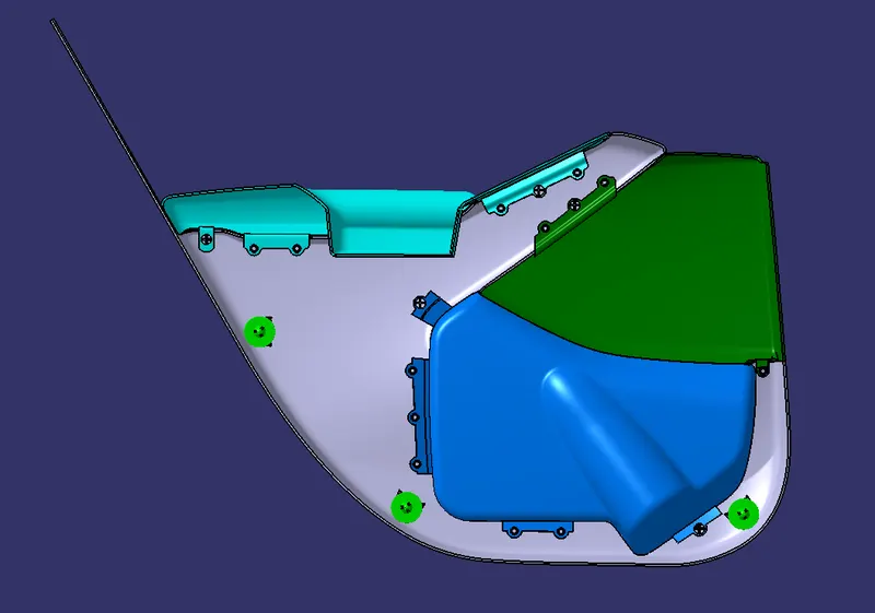
Final Images of Door Trim with B side attachments:
RESULTS:
• Class A, B and C surface was created as per the automotive standards using CATIA V5 Software.
• Draft Analysis was performed for the built model and it could be seen the the draft was under permissible limit for the manufacturing of the component.
• B side features were created for the component as per the design Rules.