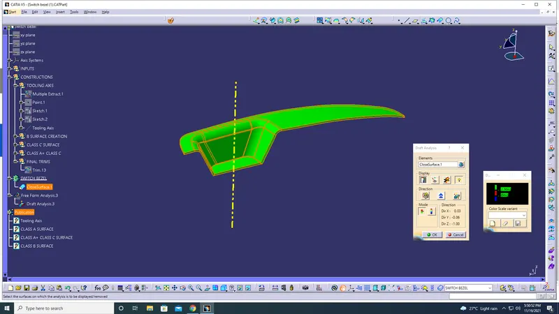
Week 8 - Challenge 3 - Switch Bezel Design
Objective:
To Create a Tooling Axis,Class B and Class C Surface with the help of Class A SURFACE of Switch Bezel Design.
Procedure:
Step-1: Creation of Tooling Axis:
- To create a proper tooling axis we should first identify which direction (ie. X,Y ,Z direction) is suitable for Tooling axis.
- Create a Geomentrical set for Tooling Axis creation.
Sketch-1 Creation
- By clicking on the Multiple Extract command on the base.Create a Point from where the tooling axis has to be consider.
- Create an Axis system on the point.
- Create a Position Sketch on YZ Plane - Projection point with reference Point - With V& H along proper directions.
- Create a Bisecting Line with the help of 2 lines created on the part.
Sketch-2 Creation
- Create a Position Sketch on ZX Plane - Projection point with reference Point - With V& H along proper directions.
- Create 1 line on the part and another line on the point with angle between two line as 3 degrees
Tooling Axis Creation
- With both lines created from Sketch-1 and Sketch-2.
- Create a Bisecting Line with the help of line command. By selecting Sketch-1+Sketch-2+Point-1.
- Press OK.
- Extend the Line to a certain distance which is visible.
- Rename the created line as TOOLING AXIS
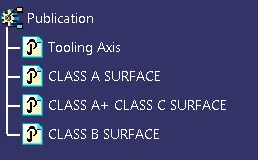
Publication of Tooling AXIS
- Publication of tooling axis is done for easy accessibility.
Screenshot for Tree Structure of Tooling Axis Creation:
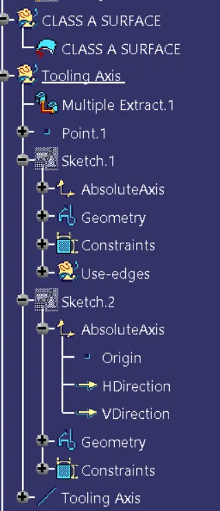
Screenshot of Publication Of Tooling Axis:

Screenshot of Point Creation:
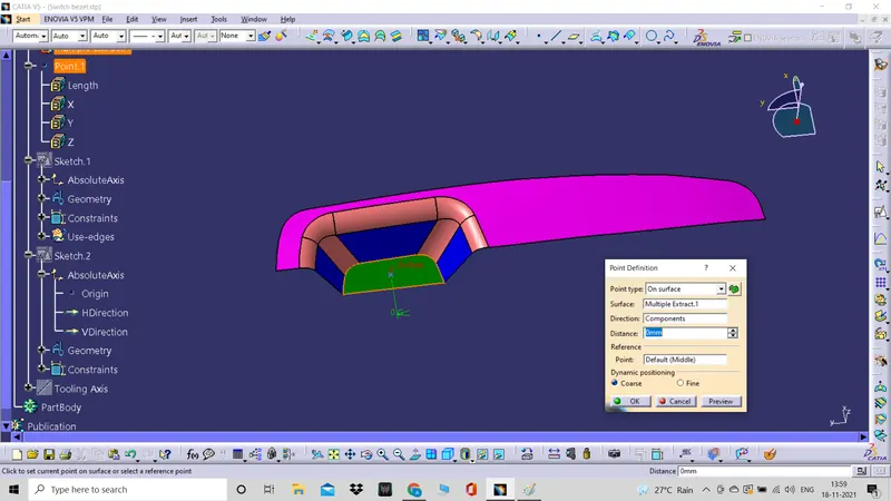
Screenshot of Sketch-1 Creation:
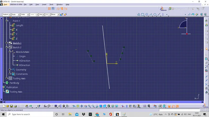
Screenshot of Sketch-2 Creation:
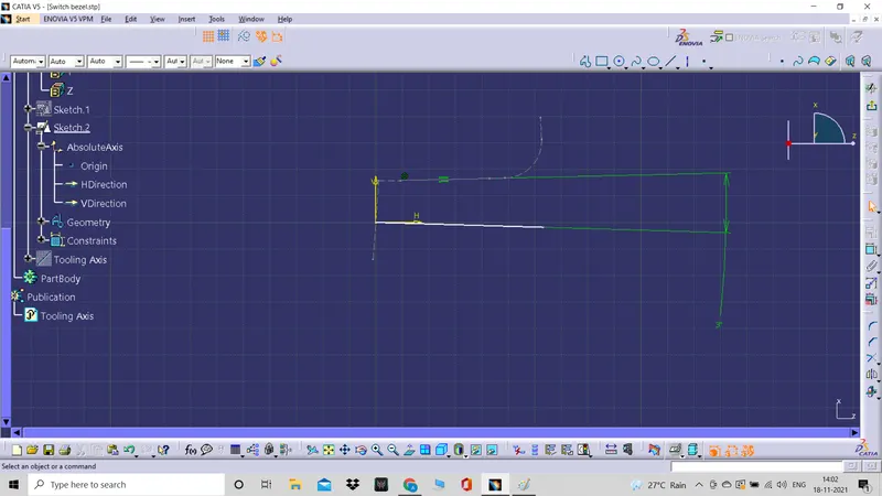
Screenshot of Tooling Axis Creation:
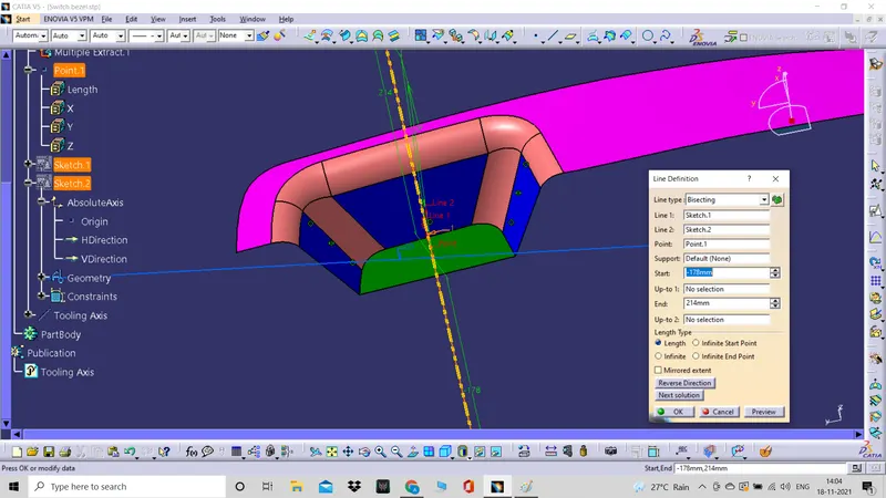
Creation of CLASS B Surface:
- For creation of Class B surface
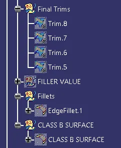
- Insert Geometrical sets for Switch Bezel Arm Rest,Walls,Base,Final Trims,Fillets
- By selecting each region Extract+Untrim+Extrampote+Offset for 3 mm
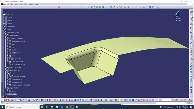
- Trim all the unwanted region to get the surface of Class B
- Measure the dimensions for all edges in Class A and apply the fillet values in Class B Surface.
Screenshot of Tree Structure for Class B Surface:
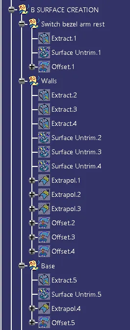
Screenshot of Class B Surface:
Creation of Class C Surface:
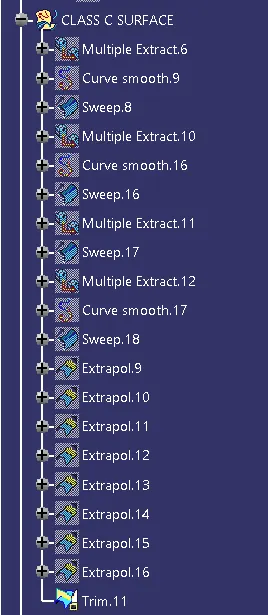
- Select the edges that is needed for Class C Surface using Multiple extract along edges.
- Use smooth curve to reduces the points of the edges.
- Use sweep command to extend the surfaces.
- Extrapol the surface if its not getting intersected.
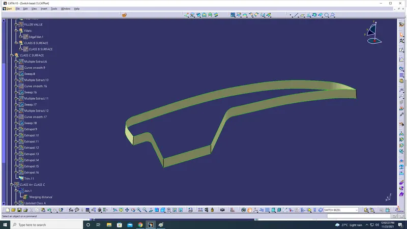
- Trim the unwanted surfaces.
Screenshot of Tree Structure for Class C surface:
Screenshot of Class C Surface:
Creation of Class A+Class C Surface:
- To create a Class A+Class C Surface use join command to join both surfaces.
- Updation of Class A surface is needed to trim along with Class C surface.
- After updating clear the unwanted edges using trim option.
Screenshot of Tree Structure of Class A+Class C:
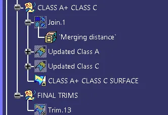
Screenshot of Class A+Class C Surface:
Screenshot of Publication of Class A, Class B & Class A+C:
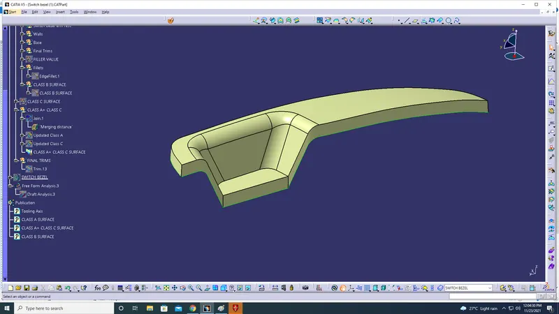
Screenshot of Final Trim after trimming with Class B + Class C:
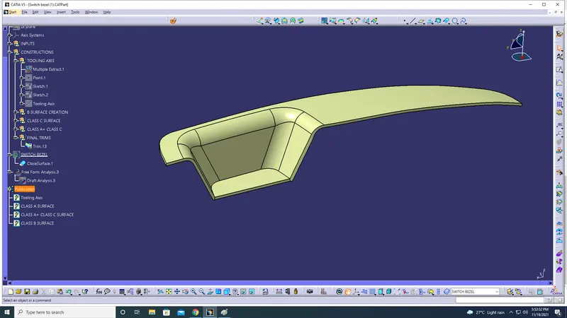
To ensure it is a proper connected part check using Boundary command:
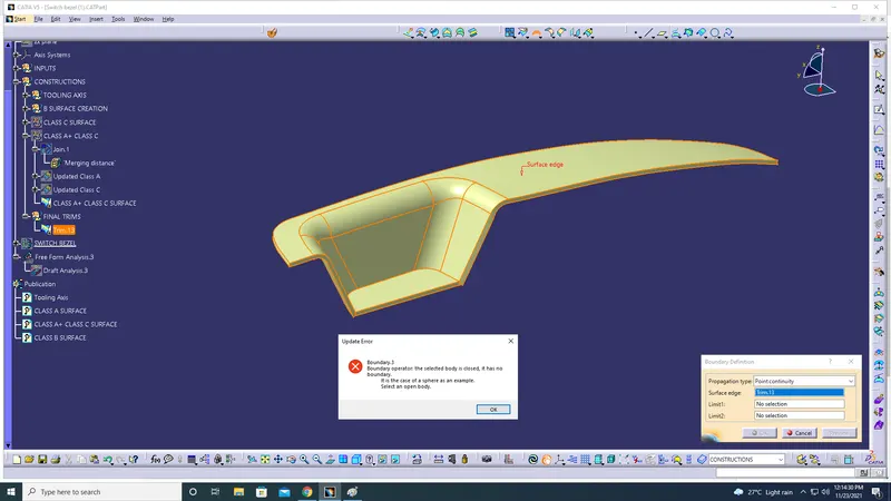
Creation of Solid Body - By using PART DESIGN - Close Surface:
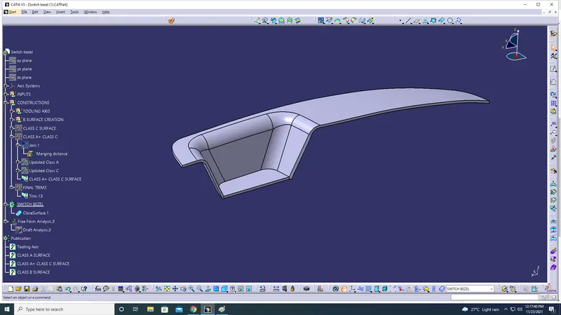
Screenshot of ISOMETRIC VIEW:
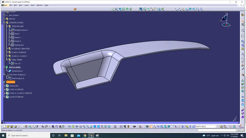
Screenshot of TOP VIEW:
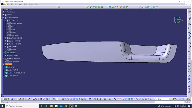
Screenshot of FRONT VIEW:
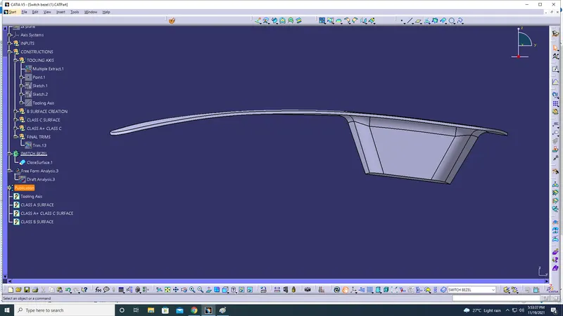
Screenshot of SIDE VIEW:
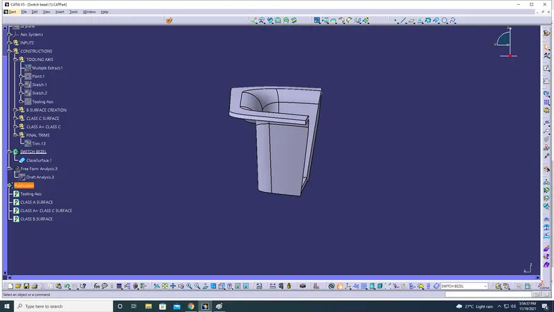
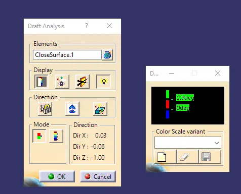
Draft Analysis of the Soild Body: