Week 8 - Challenge 2 - Base Bracket Design
Main Objective:
To Create the Tooling Axis,Class B & Class C with the help of Class A surface of Base Bracket Design.
Procedure:
Tooling Axis Creation:
1) Idetify the proper tooling axis for tooling.
- The tooling axis is feasible along the Z axis.
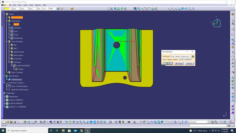
- Creation of point on the Large Hole with Point Type =Circle/Sphere/Ellipse Centre.
The screenshot for Point Creation is attached below:
2) Intersect to be created
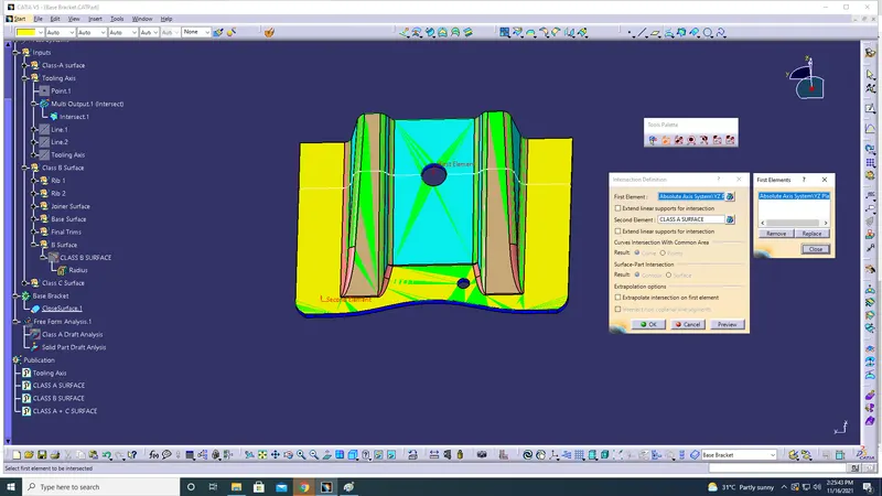
- The Intersect axis has to be selected along YZ Axis.
The screenshot for intersect line is attached below:
3) Create Bisceting Line
- Lines to be drawn on intersect line which is not parallel to dummy tooling axis.
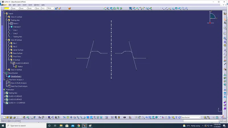
- 2 Lines are drawn on the intercect line to create tooling axis.
- To draw the Bisecting line, select the drawn 2 lines with the reference point.
The below screenshot is the 2 lines drawn on intersect line to create the Bisecting line
4) Tooling Axis Created:
The below screenshot is the tooling axis created for the component.
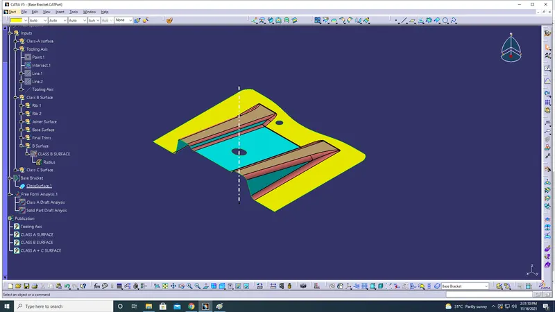
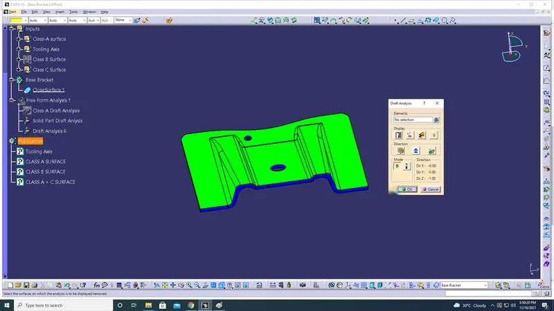
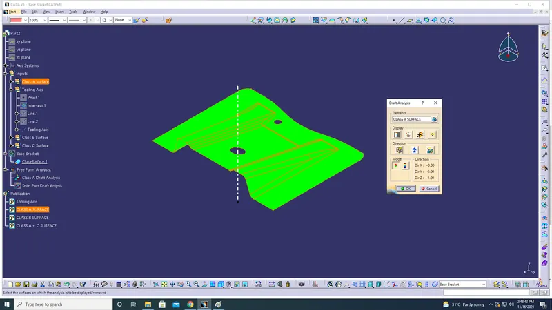
Draft Analyis of Tooling Axis for Class A Surface:
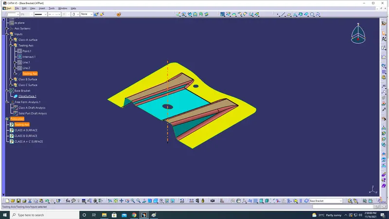
Publication of Tooling Axis
CLASS B Creation:
RIB-1 Creation
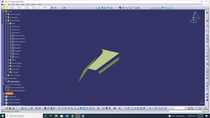
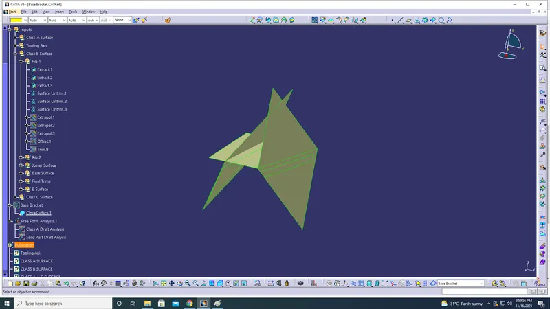
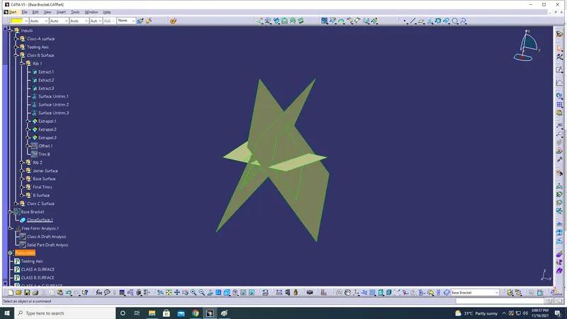
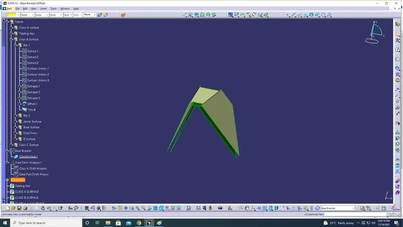
- The selected 3 Rib regions is Extacted - Untrimed -Extrapol-Offset- Trimmed
The screenshot of Tree Structure of Rib-1
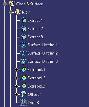
The below screenshot is Extact of Rib-1:
The below screenshot is Untrim of Rib-1:
The below screenshot is Extapol of Rib-1:
The below screenshot is Trim and Offset of RIB-1:
Creation of Rib-2:
RIB-2 Creation
- The selected 3 Rib regions is Extacted - Untrimed -Extrapol-Offset- Trimmed
- Repeat the same process as followed in contruction of Rib-1
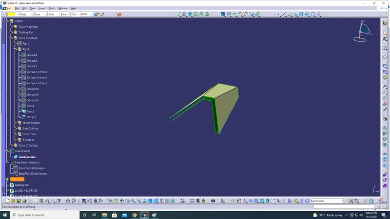
The screenshot of Tree Structure of Rib-2
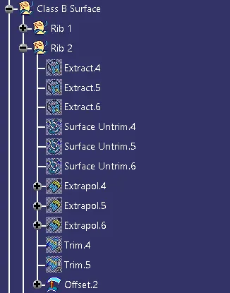
The below screenshot is Trim and Offset of RIB-2:
Creation of Class B (Joiner Surface):
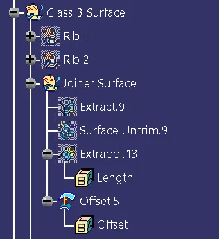
- Joiner surface is created with the help of Extract-Untrim-Extrapol-Offset
The below screenshot is the Tree Structure of Joiner Surface
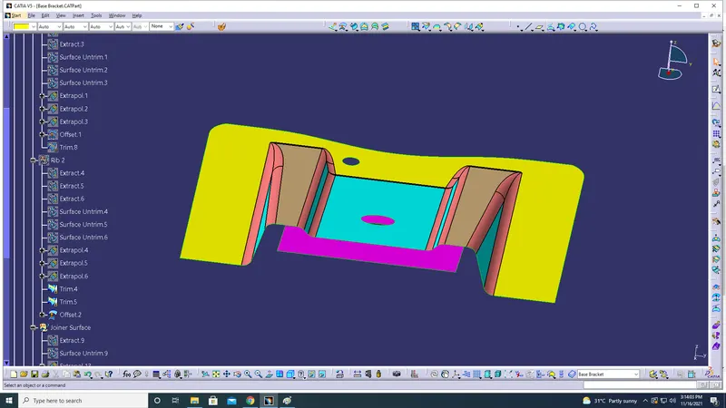
The below screenshot highligted in pink region is Class- B (Joiner Surface)
Creation Of Base Surface:
-
- Base surface is created with the help of Extract-Untrim-Extrapol-Offset.
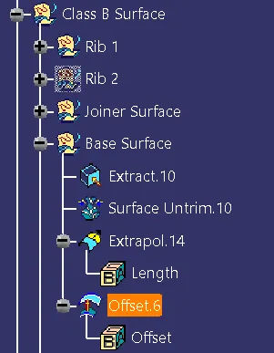
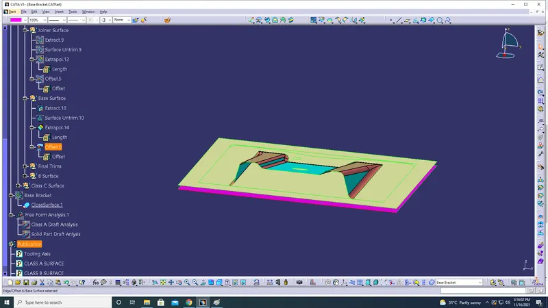
The below screenshot is the Tree Structure of Base Surface
The below highlighted pink region is Base surface of Class-B Surface:
Creation of Final Trims to Form Class-B Surface:
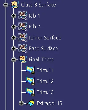
Tree Structure of Final Trims:
The below screenshot is Trim command used to create an intial Class B Surface:
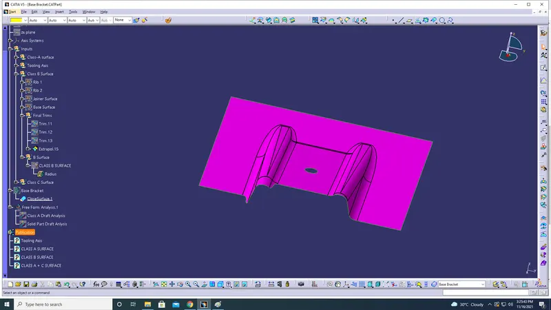
The below screenshot is Final Class-B created with fillets on edges:
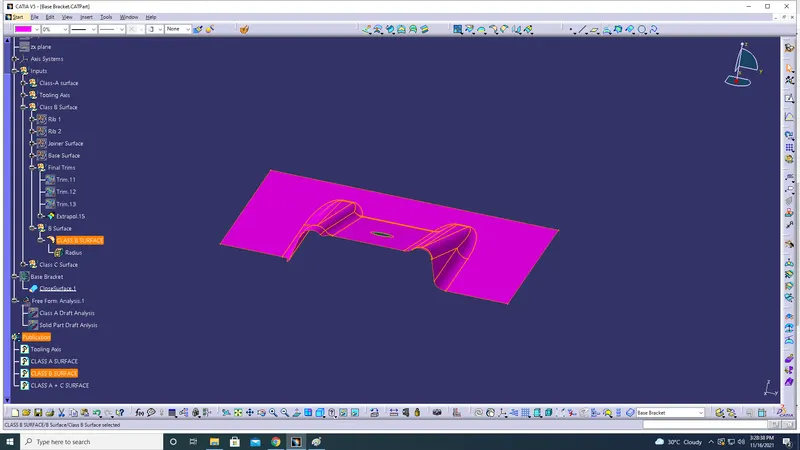
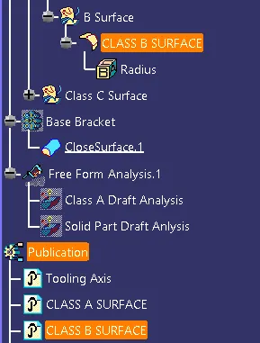
Publication of Class-B Surface:
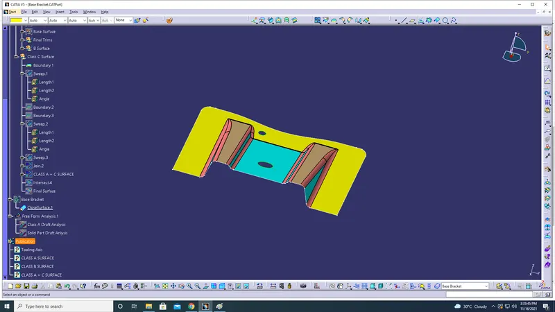
Creation Of Class-C Surface:
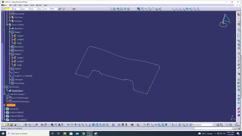
- To Create Class-C surface extract the outer region of Class-A.
- Boundary fuction to be done on the outer region.
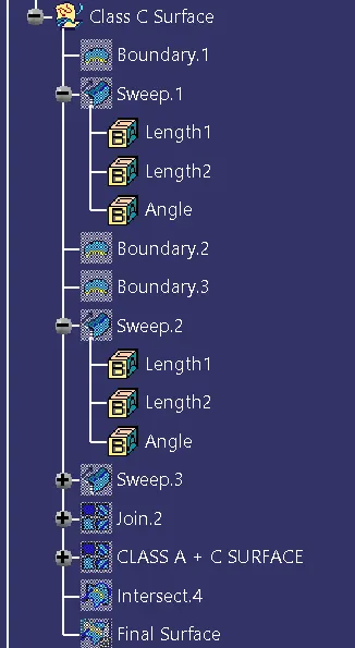
- Sweep operation is performed on Boundary-1
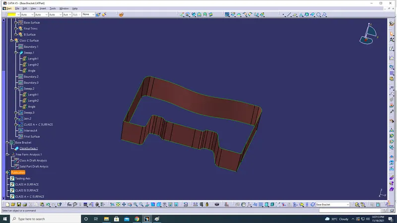
- Boundary-2 & Boundary-3 is Extracted from Class-A Surface
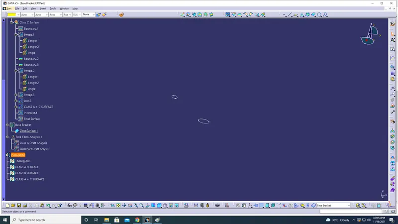
- Sweep Operation is performedon on Boundary-2 & Boundary-3 with draft angle of 3 Degree:
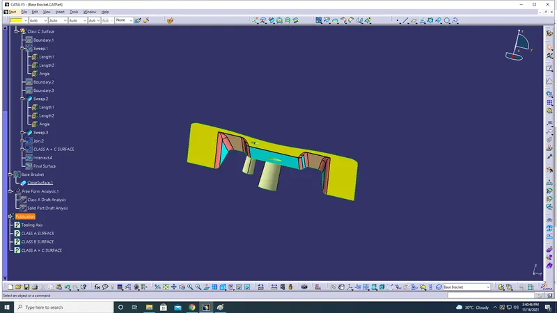
- Join Class-A & Class-C Surface:
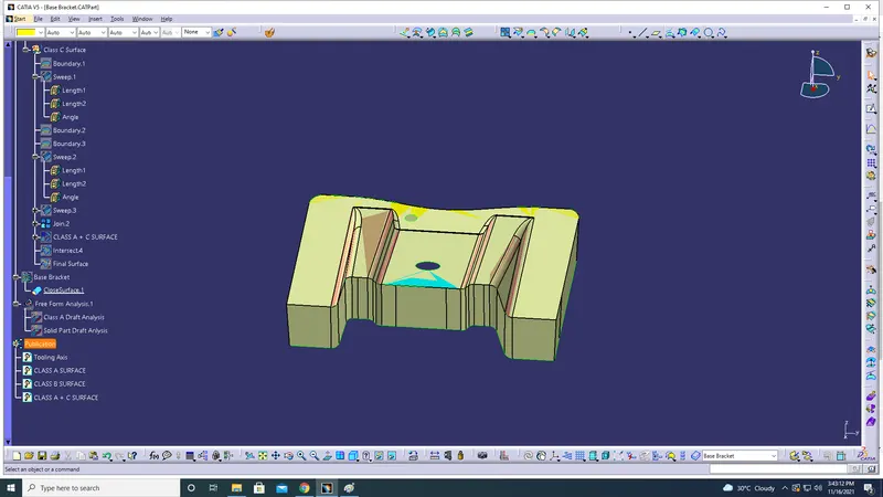
Final C Surface region:
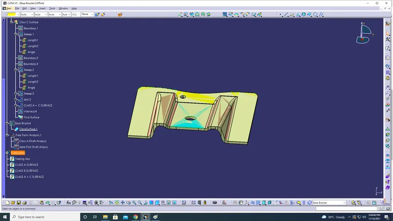
Tree Structure of Class-C Surface:
Soild Surface Creation:

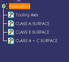
Publication of CLASS A+CLASS C SURFACE:
Draft Analysis of Soild Part: