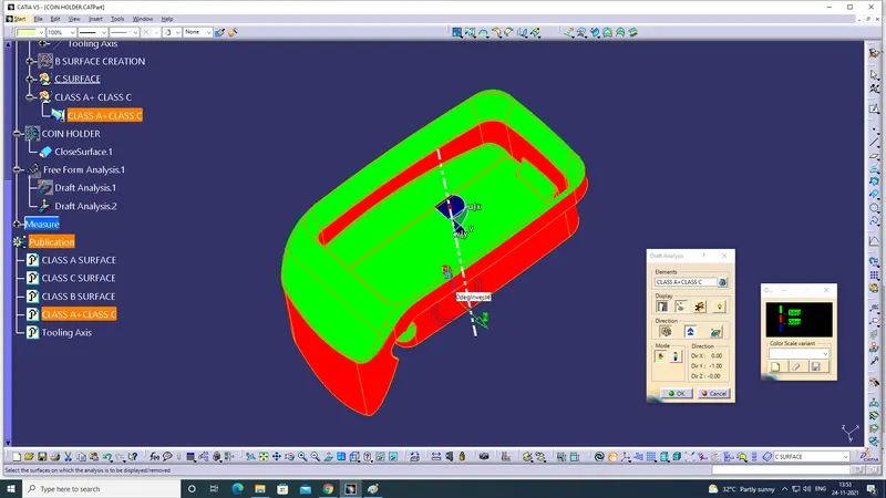
Week 8 - Challenge 4 - Coin Holder Design
Obejtive:
To create a Tooling Axis, Class B & Class C surface with the help of CLASS A of COIN HOLDER.
Procedure:
STEP-1:
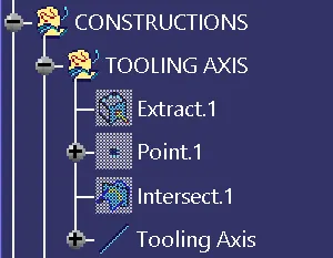
1) Creation of TOOLING AXIS:
- To create tooling axis identify the correct axis, whether X,Y,Z axis is suitable for drawing.
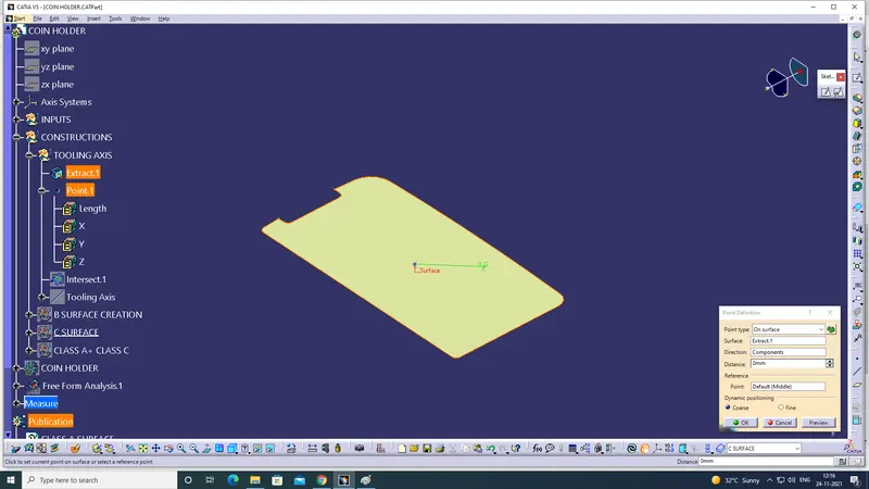
- Extract the base surface and create a point with the help of On the surface command along with distance 0mm.
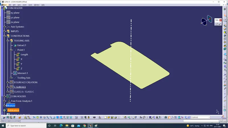
- As the CLASS A side wall surface are 0 degree. Create a line on the point along Y direction.
- The created line is changed as TOOLING AXIS.
- PUBLISH the TOOLING AXIS.
Screenshot of Tree structure for TOOLING AXIS:
Screenshot of Extract - Point created on Surface for Tooling Axis Creation:
Screenshot of Tooling Axis:
STEP-2:
Creation of B SURFACE:
1) Side Wall Creation:
- To create side wall use Extract - Untrim- Extrapol- Offset for 2.5mm- Trim the unwanted edges - Fillets on Edges.
Screenshot of Extract for Side Walls:
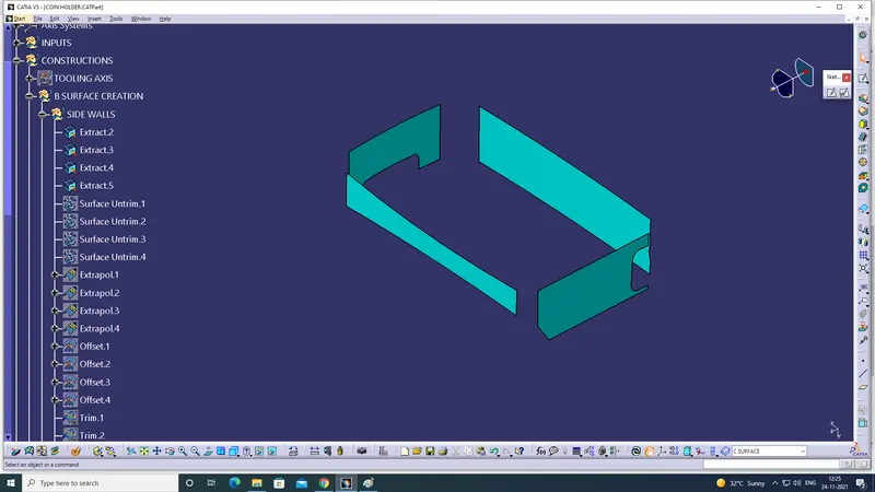
Screenshot of Untrim for Side Walls:
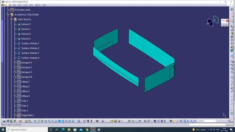
Screenshot of Extrapol for Side Walls:
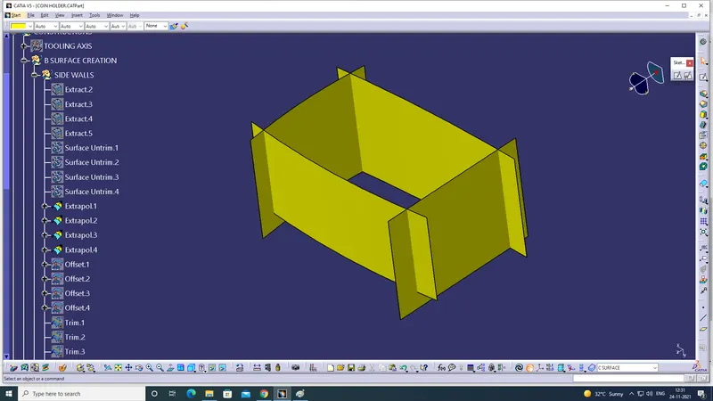
Screenshot of Offset for Side Walls:
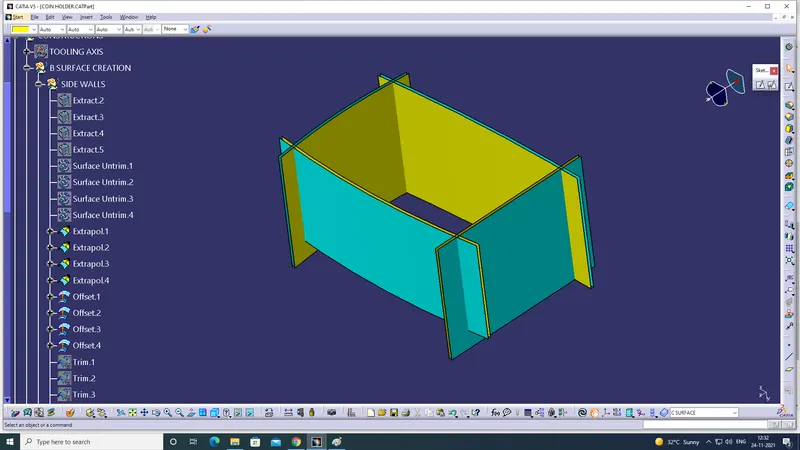
Screenshot of Trim for Side Walls:
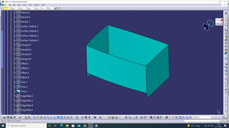
Screenshot of Edge Fillets for Side Walls:
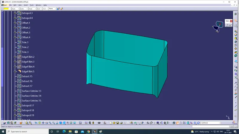
Screenshot of Small cut Box on Base:
- By using Extract - Untrim- Extrapol- Offset for 2.5mm- Trim the unwanted edges - Fillets on Edges.
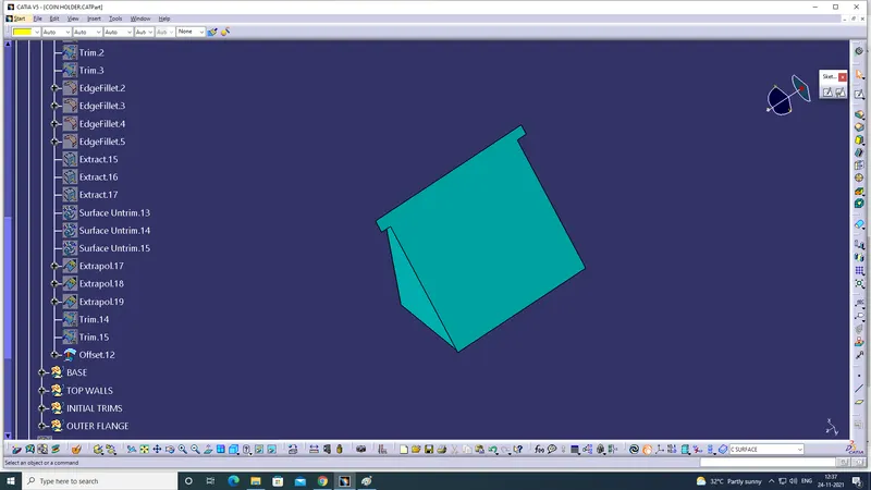
2) Base Creation:
- To create Base use Extract - Untrim- Extrapol- Offset for 2.5mm- Trim the unwanted edges - Fillets on Edges.
Screenshot of Extract used on Base surfaces:
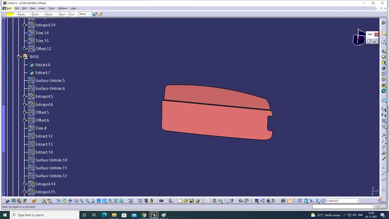
Screenshot of Untrim used on Base surfaces:
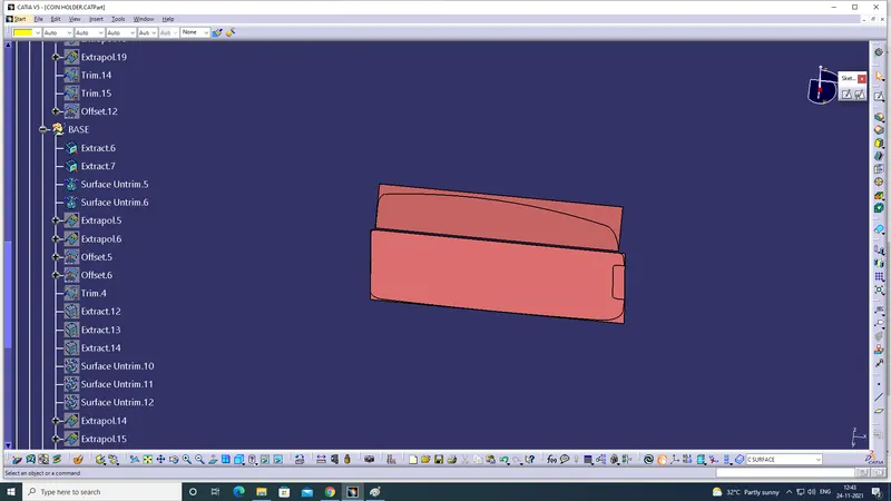
Screenshot of Extrapol used on Base surfaces:
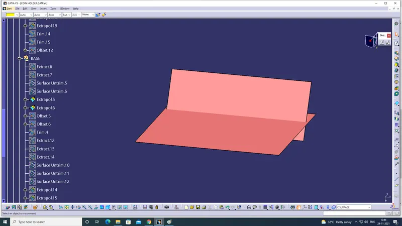
Screenshot of Offset used on Base surfaces:
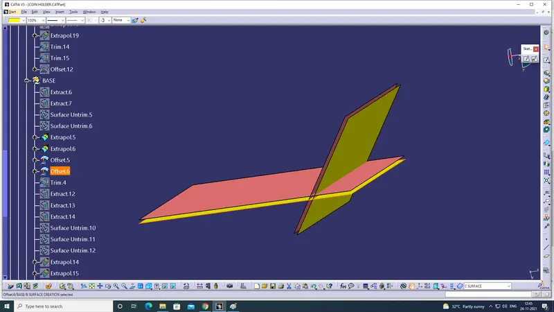
Screenshot of Trim used on Base surfaces:
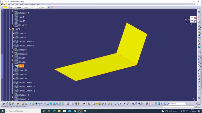
3) TOP WALL Creation:
Screenshot of Mutiple Extract of Top wall
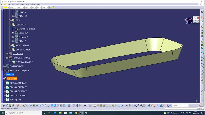
Screenshot of Extrapol of Top wall
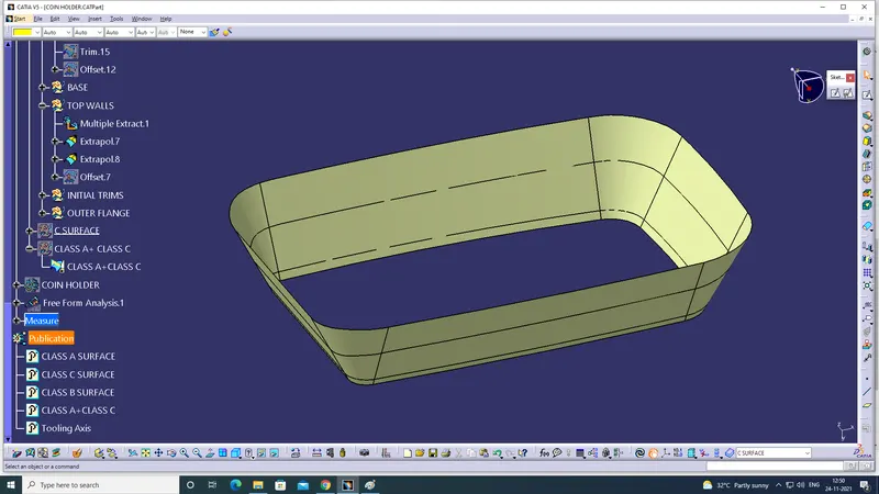
Screenshot of Offset of Top wall
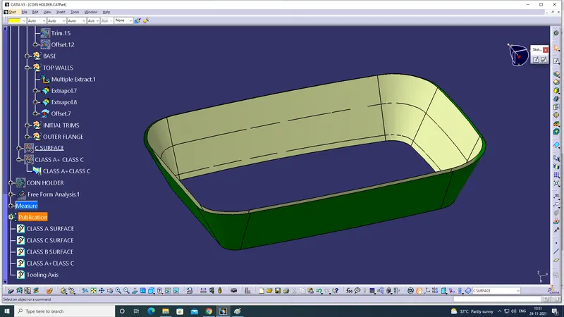
4) INITAL TRIM CREATION:
- Trim Side walls with Base to remove unwanted edges.
Screenshot of TRIM COMMAND used on Side walls with Base to remove unwanted edges.
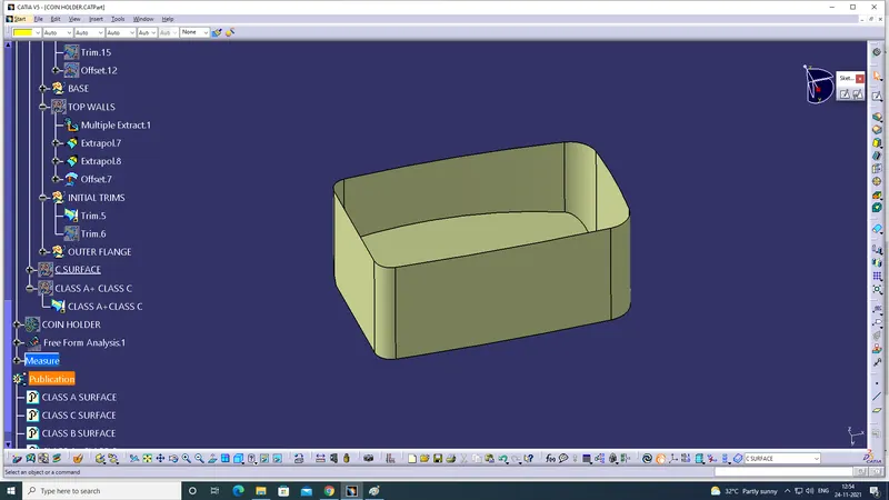
- Trim Side walls with Base to remove unwanted edges.
Screenshot of TRIM COMMAND used on Trim 5 and TOP WALL to remove unwanted edges.
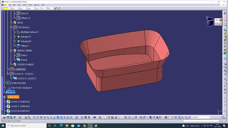
5) OUTER FLANGE CREATION:
Screenshot of Multiple Extract on FLANGE Surface:
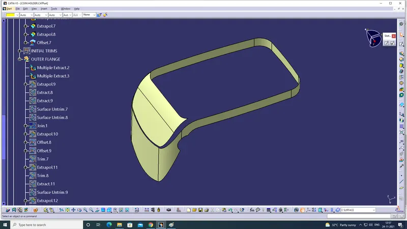
Screenshot of Extrapol on the Top edges of Multiple Extract.2 of FLANGE Surface:
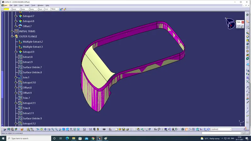
Screenshot of Extract of FLANGE Surface:
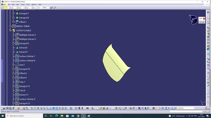
Screenshot of Untrim of FLANGE Surface:
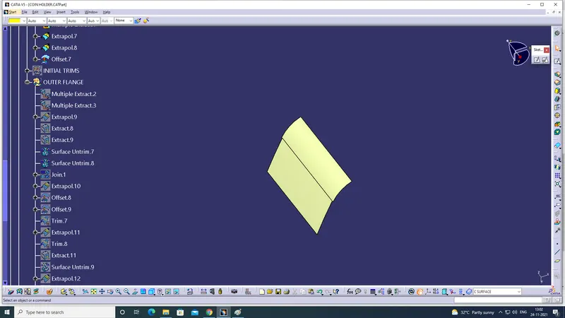
Screenshot of Join of FLANGE Surface:
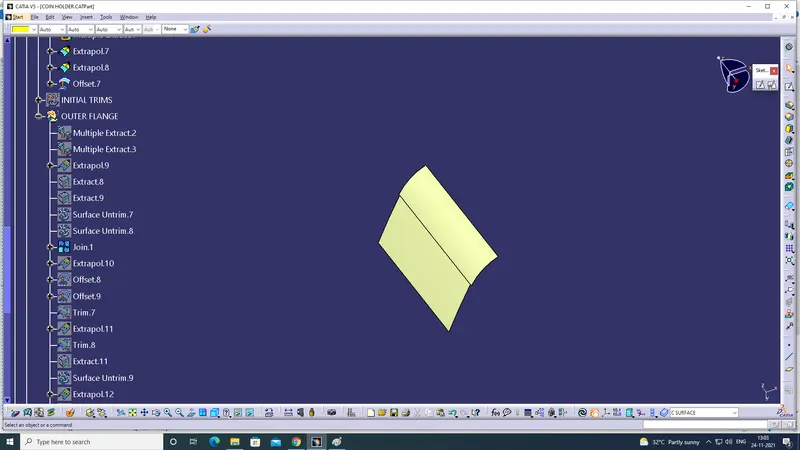
Screenshot of Extrapol of FLANGE Surface:
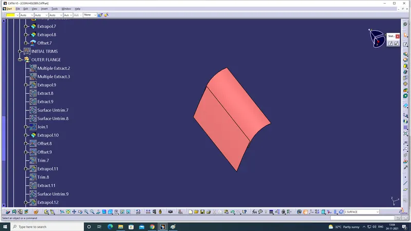
Screenshot of Offset of FLANGE Surface:
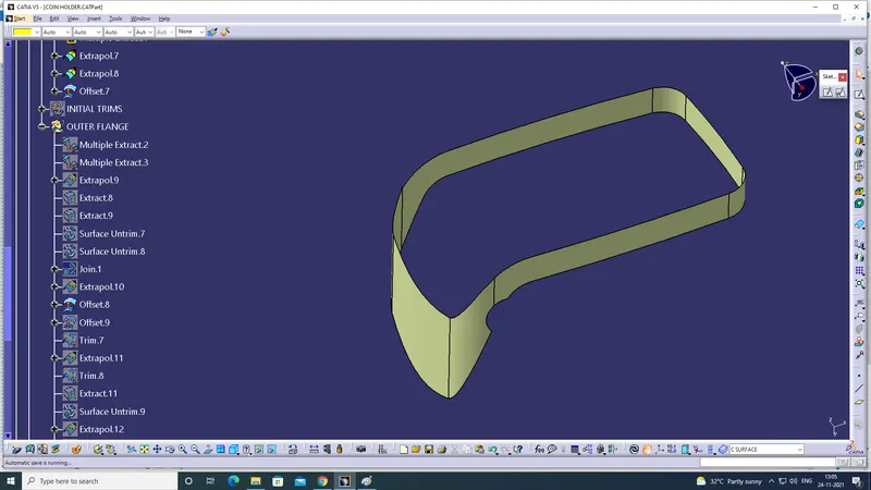
Screenshot of Offset of FLANGE Surface:
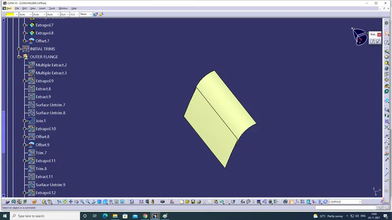
Screenshot of TRIM of 2 FLANGE Surface:
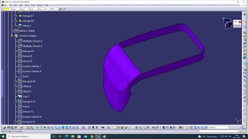
Screenshot of EXTRAPOL on the edge as it is not getting Trimmed Surface:
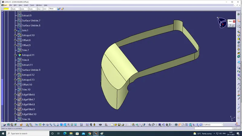
Screenshot of Trim:
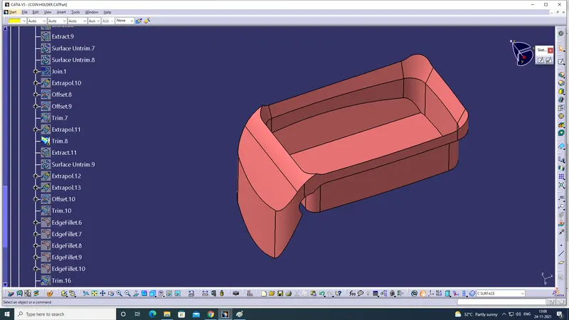
Screenshot of the Edge Projection
- Select a small region Extract-Untrim-Extrapol-Offset
Screenshot of Extract & Untrim command:
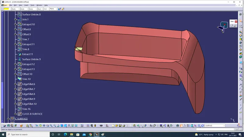
Screenshot of Extrapol command:
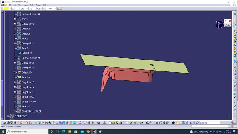
Screenshot of Offset command:
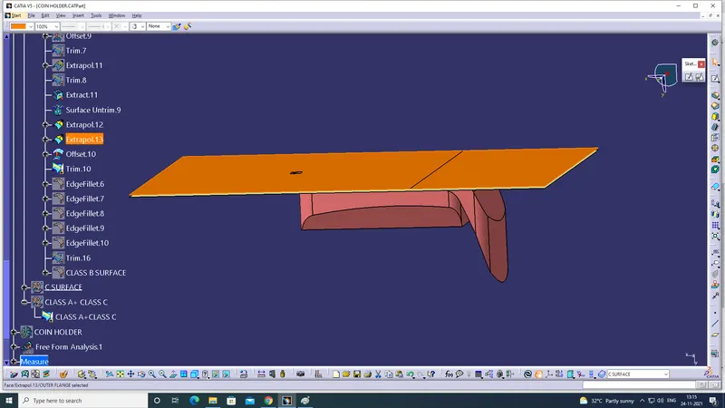
Screenshot of Trim command:
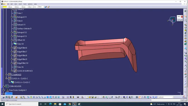
Screenshot of Edge Fillet command used on Edges:
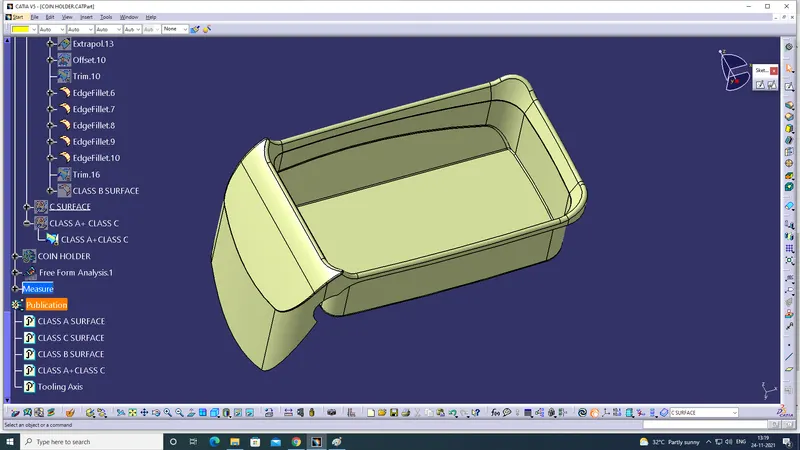
Screenshot of FINAL CLASS B SURFACE:
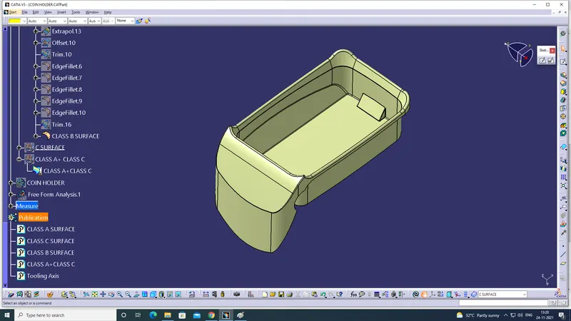
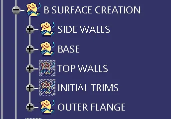
Screenshot of Tree Structure of B Surface:
STEP-3:
Creation of C Surface:
Screenshot of Multiple Extract of Edges:
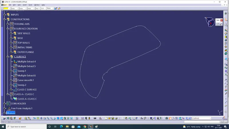
Screenshot of Multiple Extract of Surfaces:
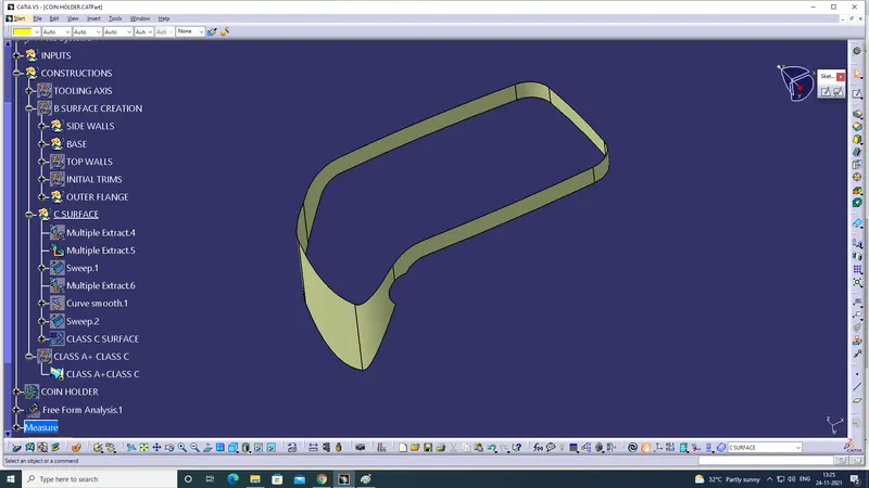
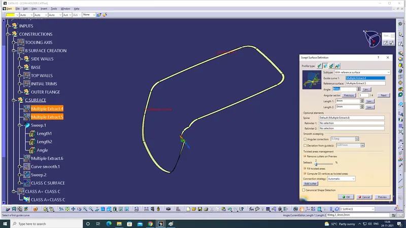
Screenshot of Sweep command - With reference surface- Guide curve(Multiple Extract.4)- Reference Surface(Multiple Extract.5)- Angle(90 Degree)- Select Direction Inward- Length 1: 4mm:
Screenshot of Hole creation using Multiple extract along edges from Class-A:
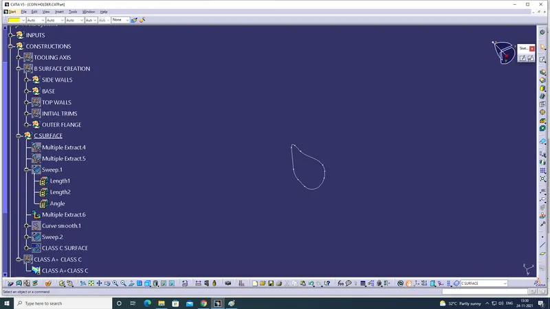
Screenshot of smooth curve on Mutiple Extract:
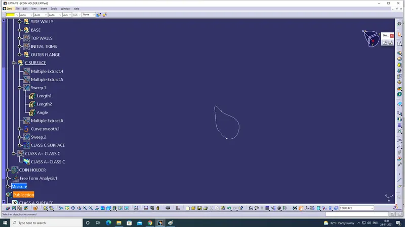
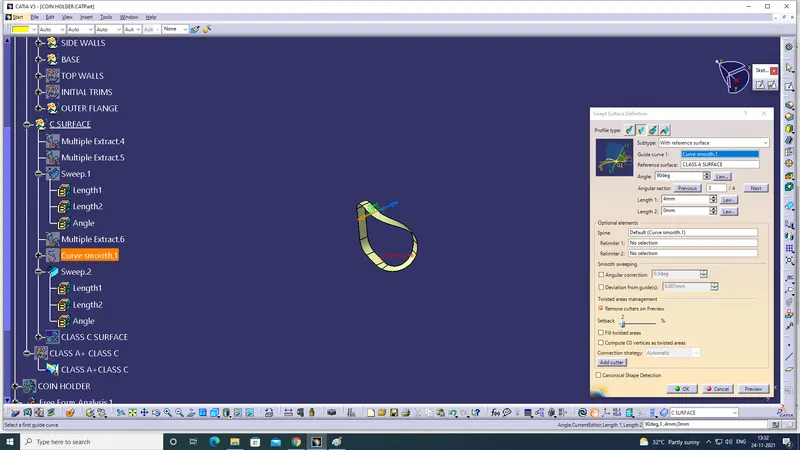
Screenshot of Sweep command - With reference surface- Guide curve(Curve Smooth-1)- Reference Surface(Class A Surface)- Angle(90 Degree)- Select Direction Inward- Length 1: 4mm:
STEP-4:
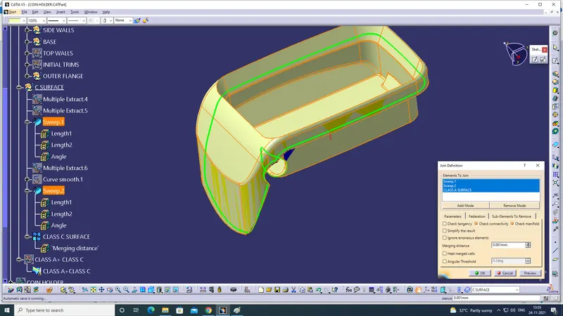
Screenshot of Join command with Sweep.1+Sweep.2+Class A Surface:
- Join Class C+Class A.
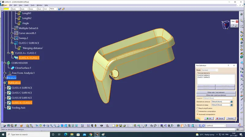
Screentshot of Final Trim bu selecting Class B+Class C Surface:
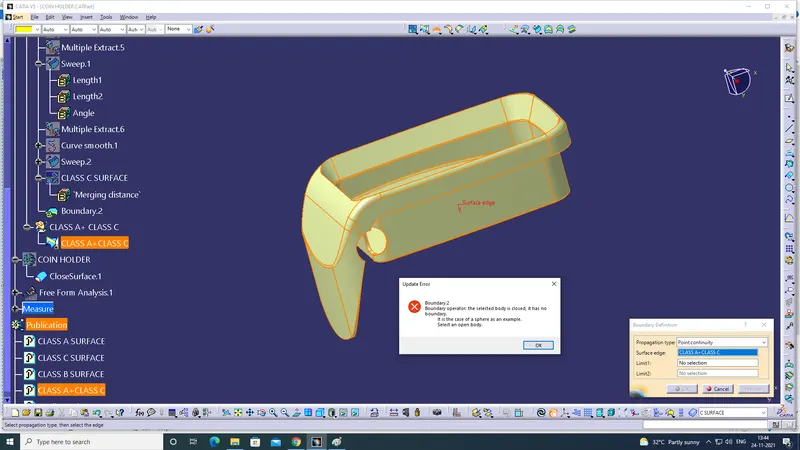
Screenshot to check all surface are connected: Select Boundary option and check
STEP-5:
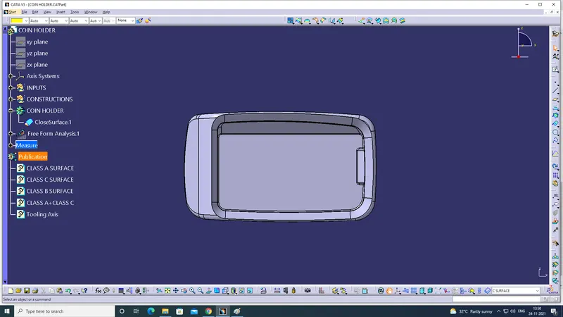
Screenshot of Component coverted into Soild Body by Close Surface command from Part Design workbench:
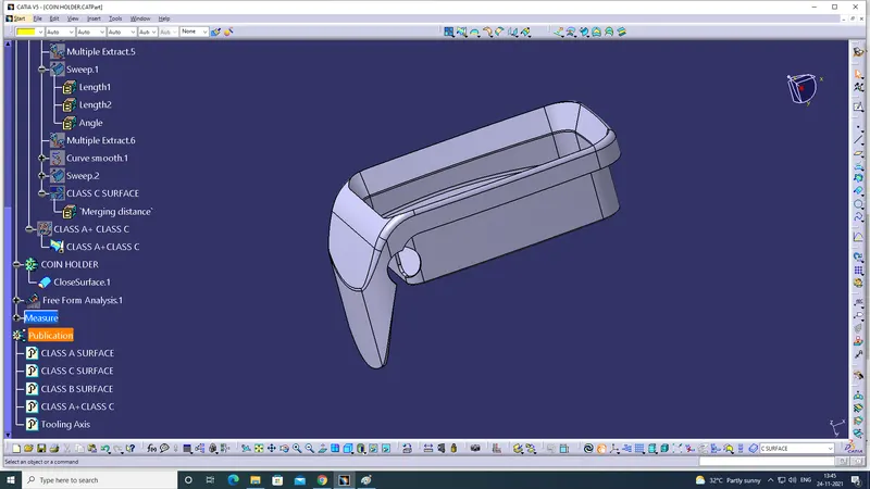
Screenshot of Isometric View:
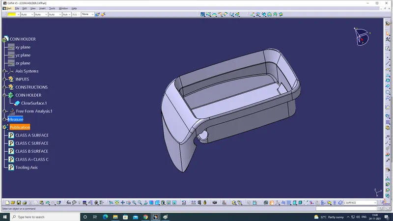
Screenshot of Front View:
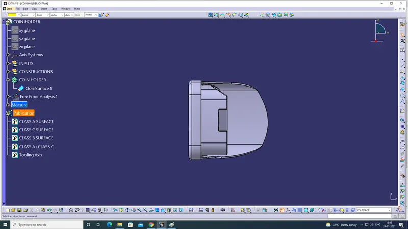
Screenshot of TOP View:
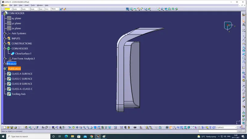
Screenshot of SIDE View:
STEP-6:
Draft Analysis of the Component: