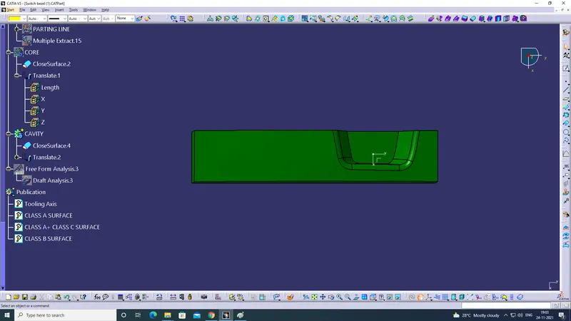
Week 8 - Challenge 5 - Core & Cavity Design
Objective:
To create a Core and Cavity of Switch Bezel.
Procedure:
Creation of Parting Surface:
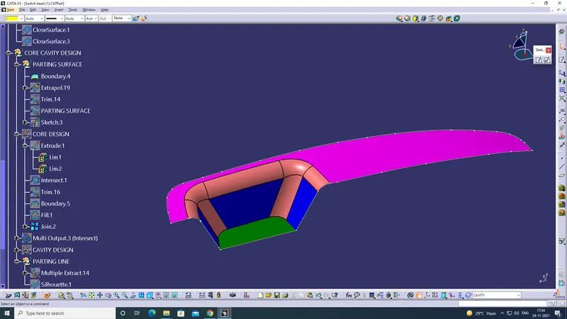
- To create parting surface select boundary command on Class A surface.
- It gives outer line of Class A.
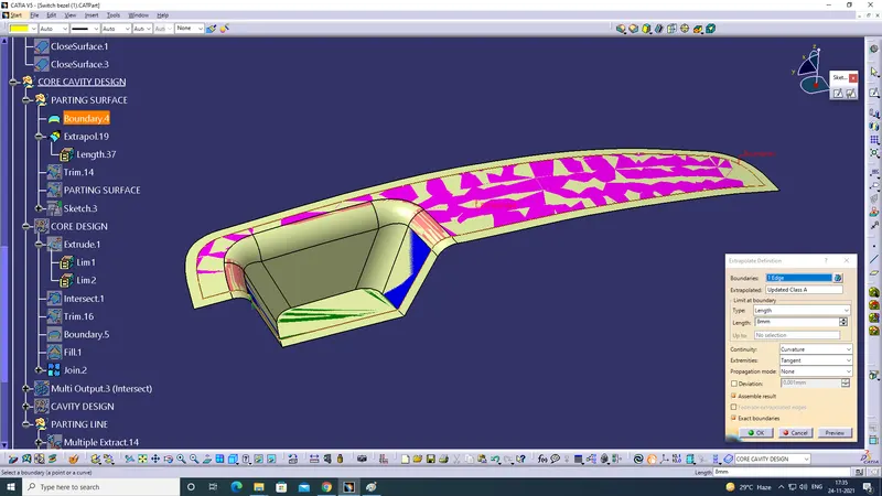
- Extrapol the Class A Surface.
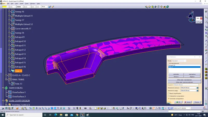
- Trim the outer edges by selecting Extrapol.19 and Trim.11 i.e the Class C Surface.
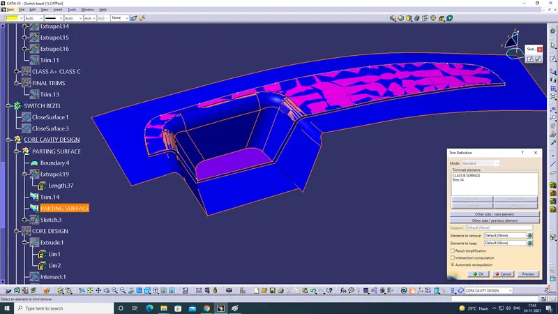
- Trim the unwanted region by selecting Class B surface and Trim.14.
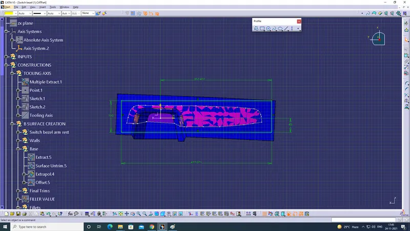
- Draw a Rectangle with Sketch with an Axis sytem on the base along
Screenshot of Boundary on Class A Surface:
Screenshot of Extrapol command used on Class A Surface:
Screenshot of Trim Command used on Extrapol.19 and Trim.8:
Screenshot of the Trim command used on Class B surface and Trim.14:
Screenshot of Rectangle drawn with Sketch along XY Plane:
Creation of Core Design:
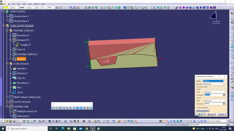
- To Create Core Degin Extrude the Rectangle ie. Sketch.3 along the Tooling Axis for 150mm.
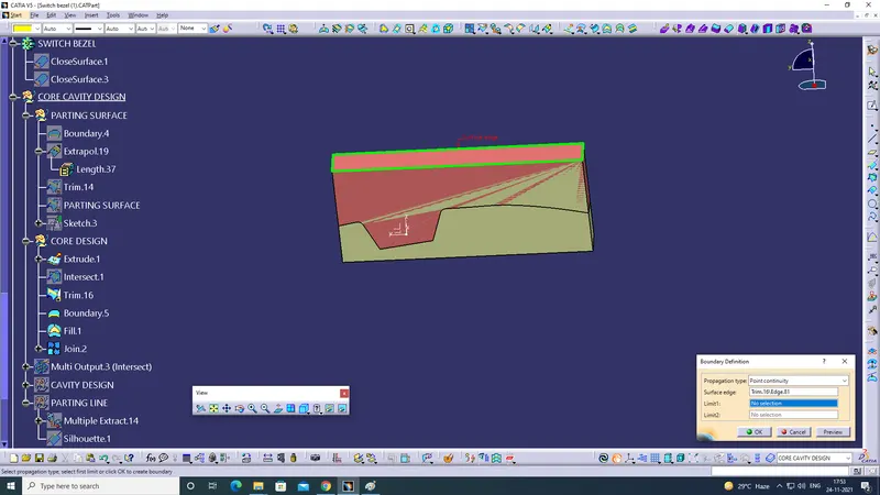
- Use boundary on the Top edges.
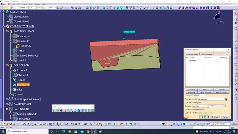
- To close the top use Fill command.
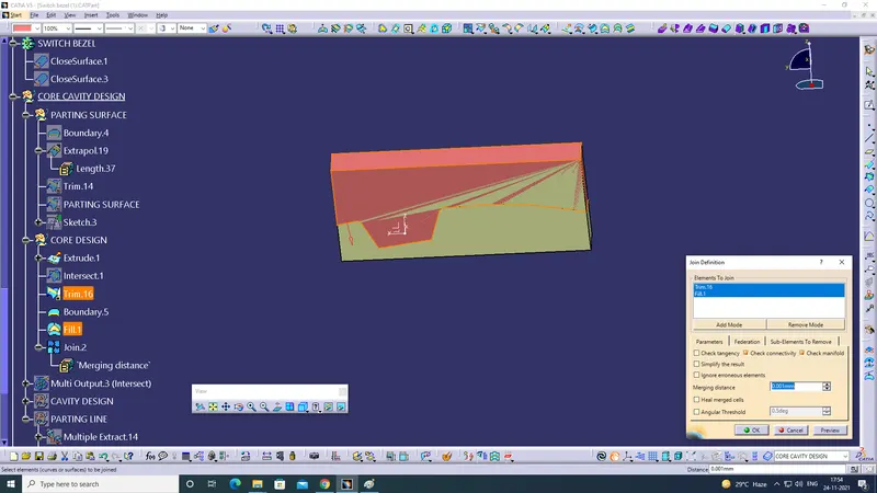
- Join the Trim.16 and Fill.1
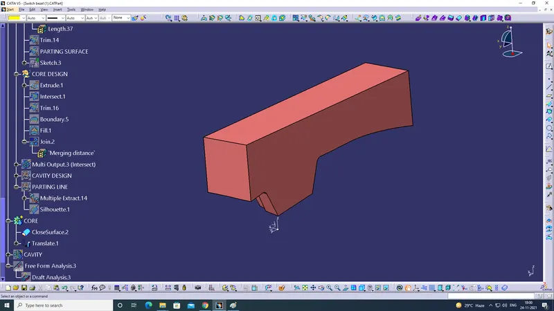
- Convert the joined surface to a soild body by close surface from Part Design.
Screenshot of Extrude command used on the Rectangular Sketch:
Screenshot of Bounadry command used on the Top Edges:
Screenshot of Fill command used to close the TOP surface:
Screenshot of Join command used to Join the Trim.16 and Fill.1:
Screenshot of Core to Soild Body:
Creation of Cavity Design:
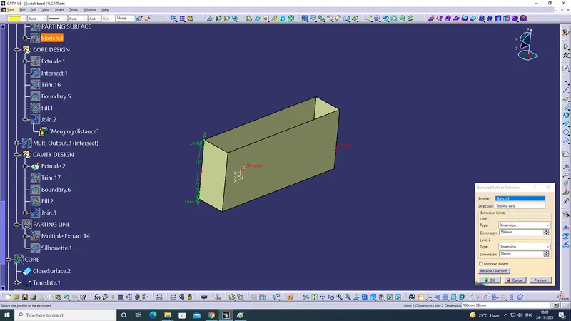
- To create the cavity design extrude the rectangualr surface.
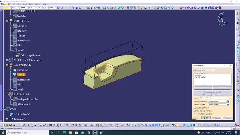
- Trim the Extrude.2 along with CLASS B Surface.
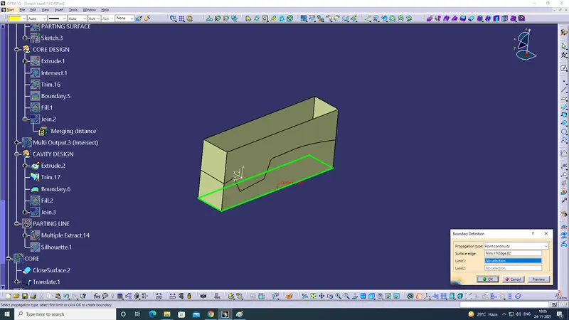
- Use Boundary command to select the bottom edges.
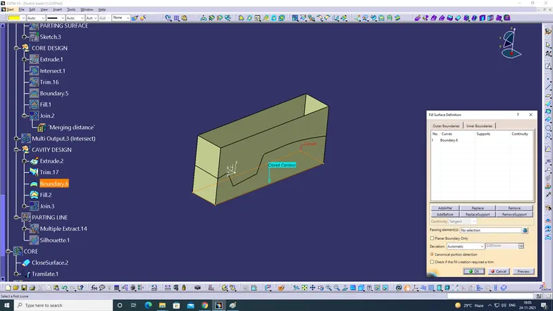
- Use Fill command to close the bottom side.
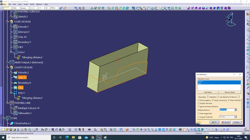
- Join Extrude and Fill to create a closed surface.
- Convert the joined surface to a soild body by close surface from Part Design.
Screenshot of extrude command on the cavity side:
Screenshot of Trim command on the Extrude.2 along with CLASS B Surface:
Screenshot of Boundary command used on the bottom edges:
Screenshot of Fill command used on the boundary to close the bottom surface:
Screenshot of Join Command used to join the TRIM and Fill:
Screenshot of Body of Cavity:
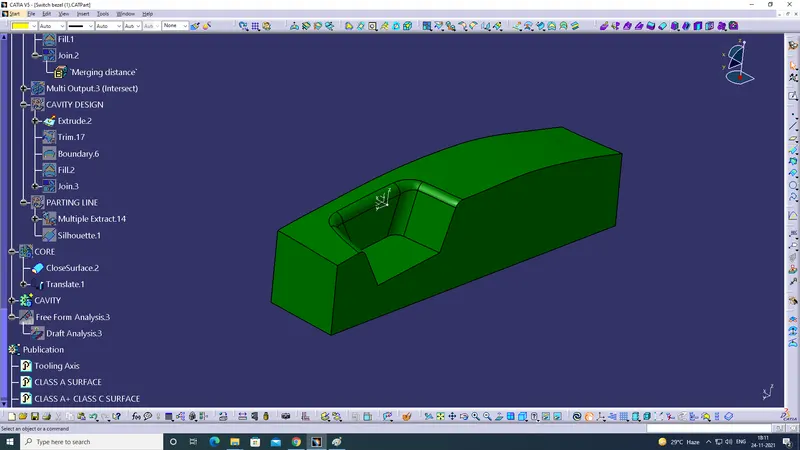
Screenshot of Parting Surface,Core,Cavity,Parting Line:
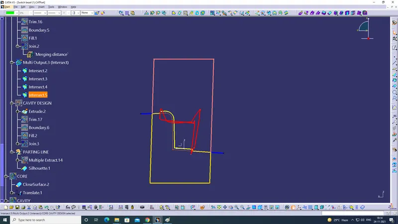
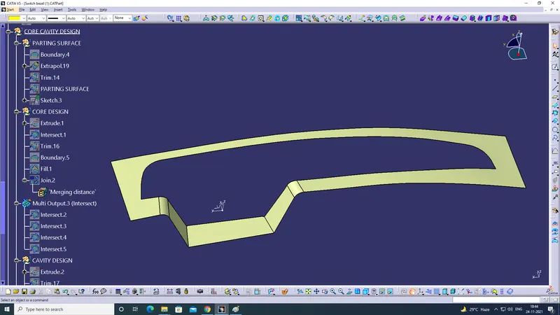
Screenshot of Parting Surface:
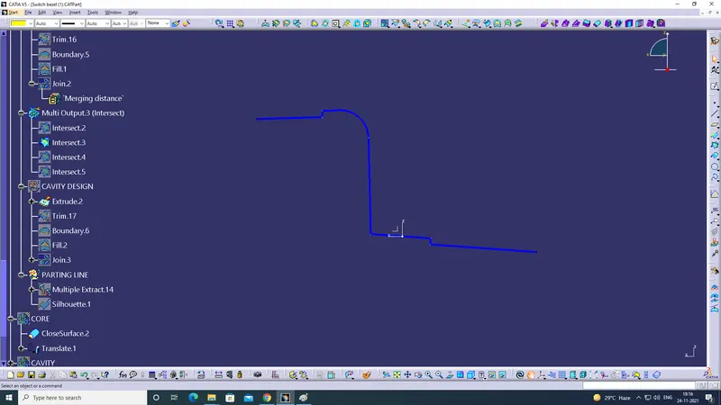
Screenshot of Core:
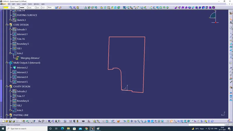
Screenshot Of Cavity:
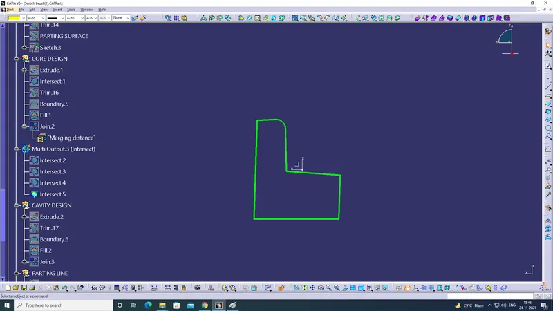
Screenshot Parting Line:
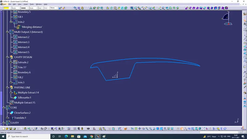
Creation Of Parting Line:
- To create Parting Line Multiple Extract the Class A edges.
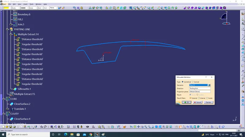
- Use Sihouette command using MUTIPLE Extract and Tooling AXIS.
Screenshot of Multiple Extract on Class A edges:
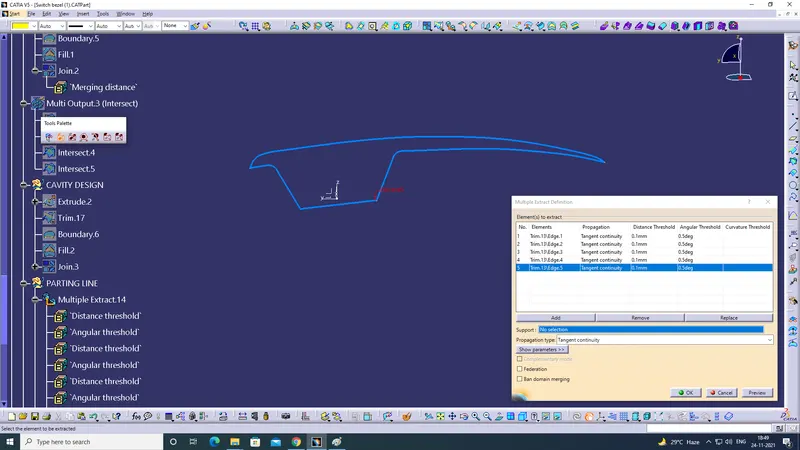
Screenshot of Sihouette command using MUTIPLE Extract and Tooling AXIS.
Translate the Core and Cavity:
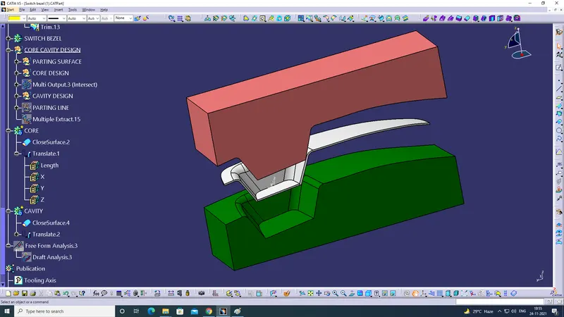
Screenshot of Core in Isometric View:
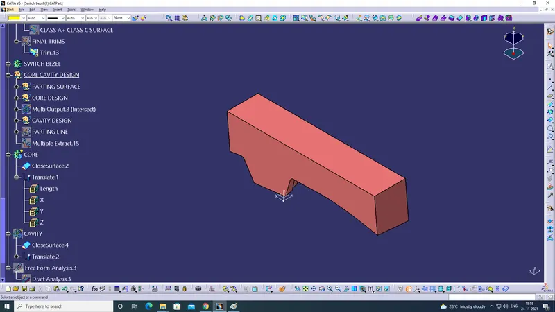
Screenshot of Core in Front View:
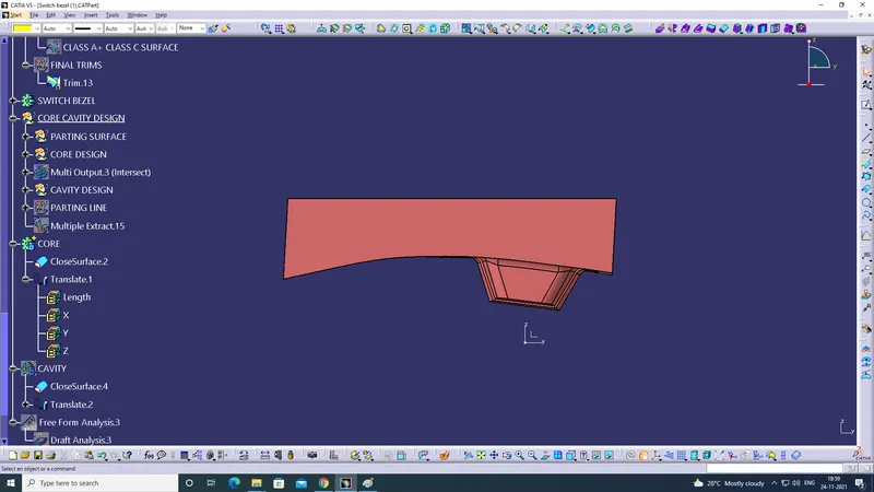
Screenshot of Core in Top View:
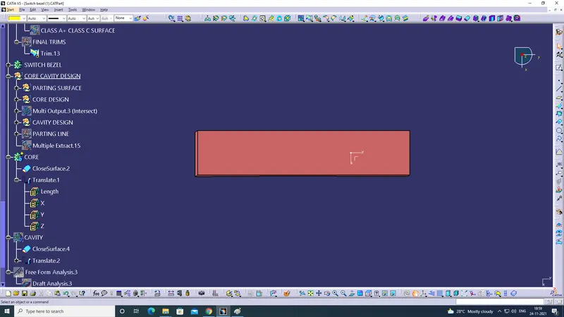
Screenshot of Core in Bottom View:
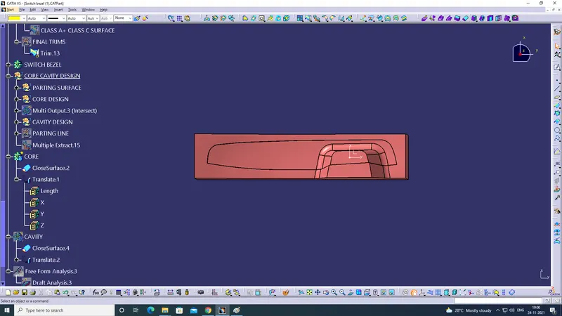
Screenshot of Cavity in Isometric View:
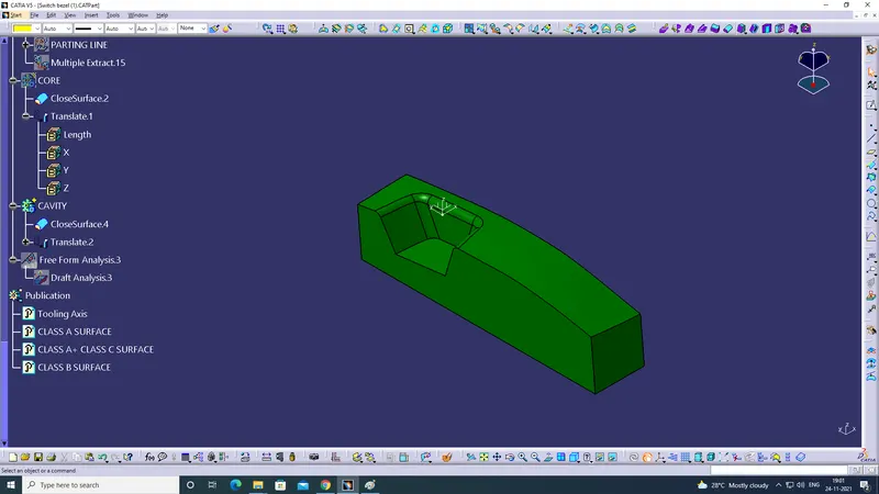
Screenshot of Cavity in Front View:
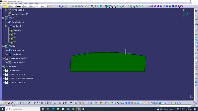
Screenshot of Cavity in Side View:
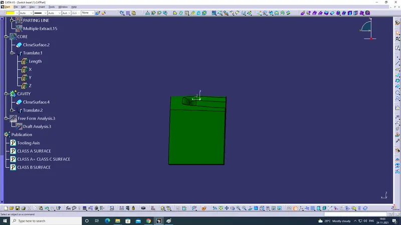
Screenshot of Cavity in Top View: