Week 11 - Final project
DEVELOPMENT OF DOOR TRIM
OBJECTIVE:
To design and develop a door trim panel incorporating all the engineering features in it following the input,master section and plastic design regulations.
REQUIREMENTS:
- To create an appropriate tooling direction for the respective class A surfaces of arm rest,lower substrate,map pocket and bottle holder.
- Draft analysis check for class A.
- To design class B and C surfaces.
- To integrate the required B side features in relevant places of a component
- To perform a draft analysis on the final component.
DOOR PANEL:
Door panel is an interior plastic component which goes and assembles to the sheetmetal component of a door. A door trim itself is an assembly comprising of arm rest,carrier,map pocket,door applique,carrier,lower substrate,top roll,bottle holder etc.,Each plastic component is designed seperately and assembled together as a door trim.
INPUT:
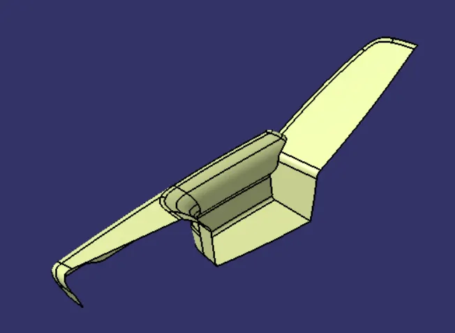
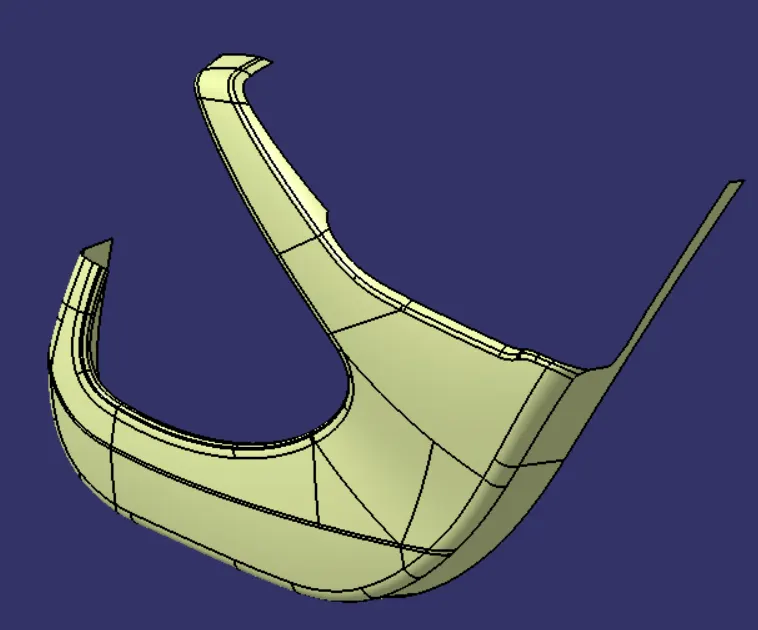
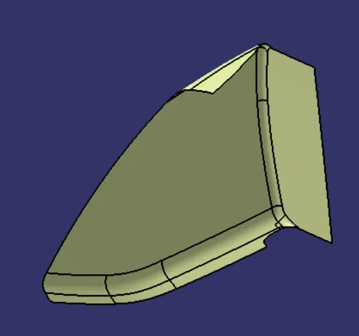
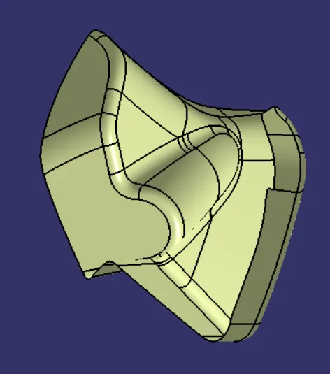
Class A:
Arm rest:
Lower substrate:
Map pocket:
Bottle Holder:
Master section:
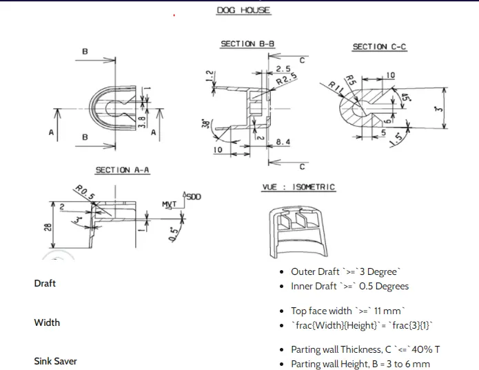
Dog House input:
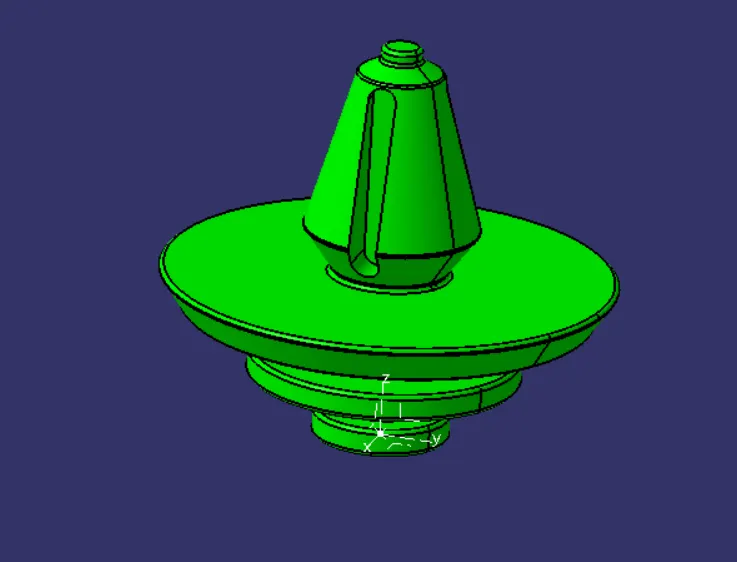
Push pin:
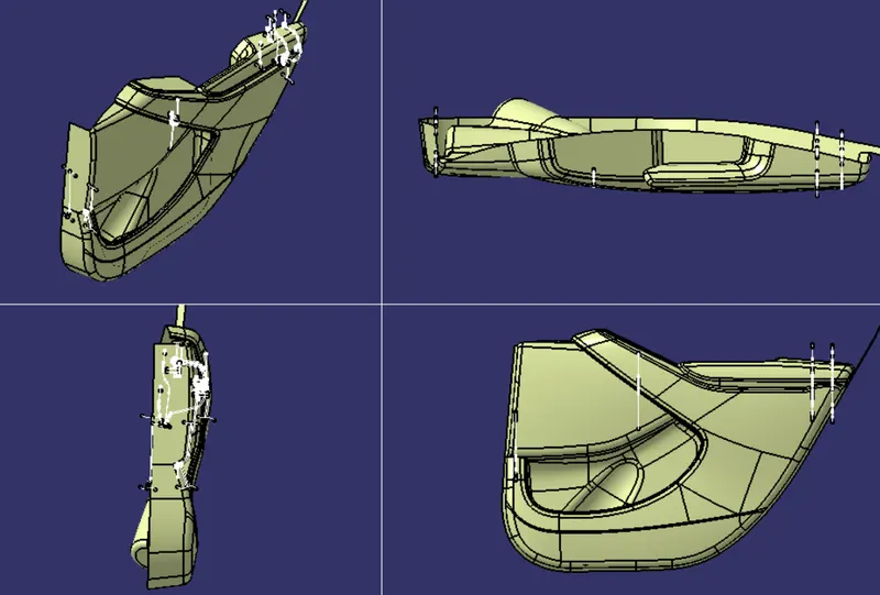
TOOLING DIRECTION:
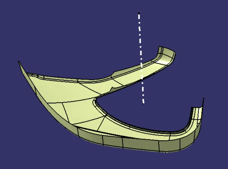
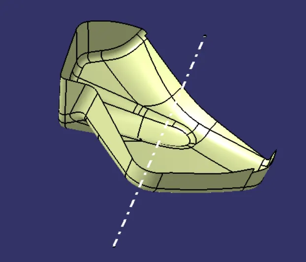
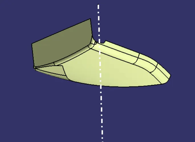
After inspecting of the surface,the tooling direction is created for the respective surfaces duly.
Tooling direction is determined based on the complexity of the surface.
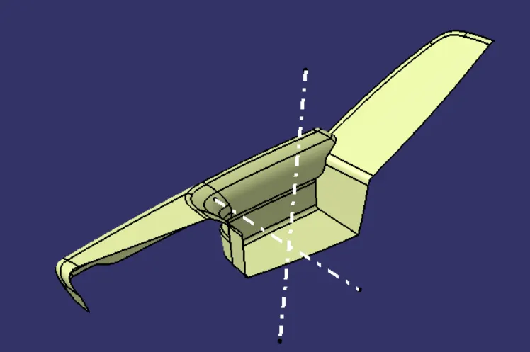
Surfaces which do not clear in the main tooling are cleared using the side core.
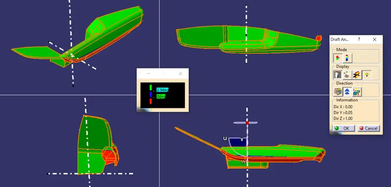
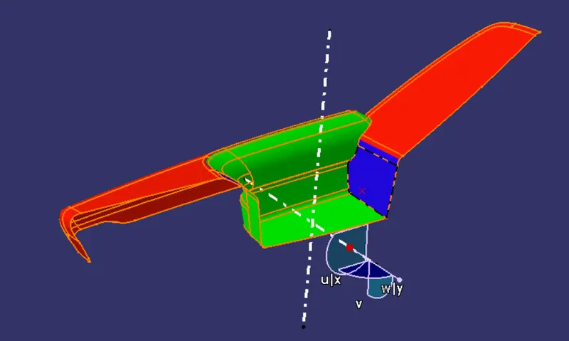
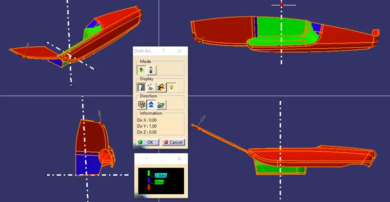
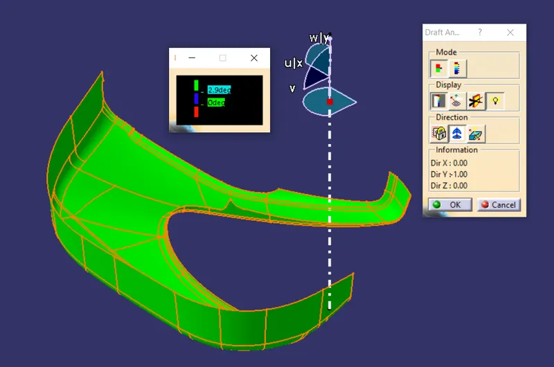
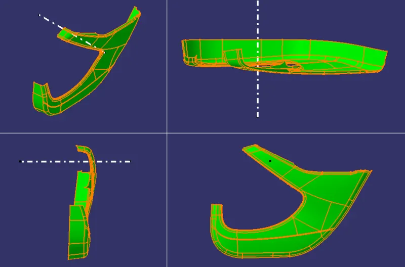
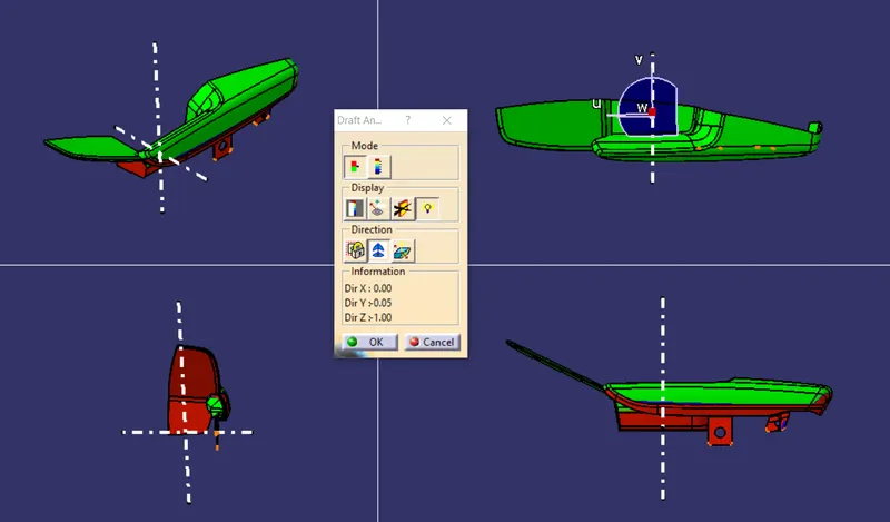
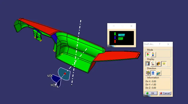
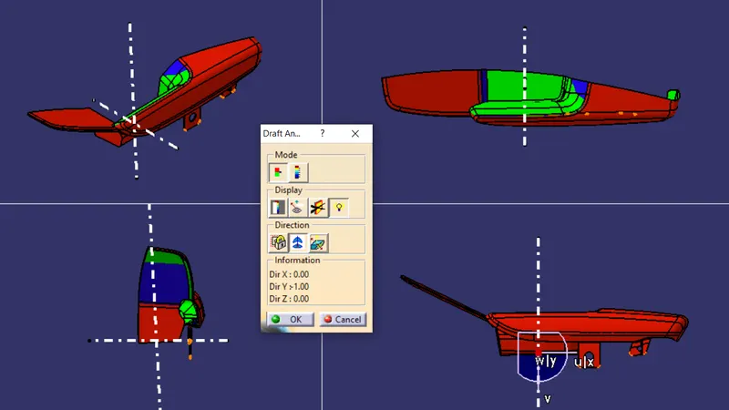
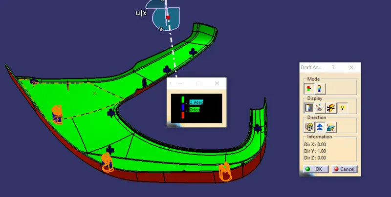
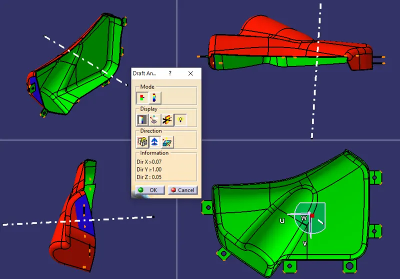
DRAFT ANALYSIS ON CLASS A:
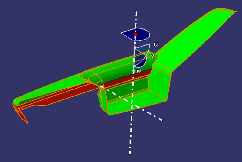
Arm Rest
Main Tooling:
Side Core:
Lower Substrate
Bottle Holder
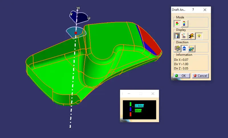
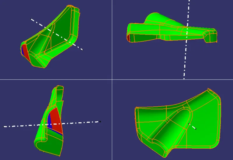
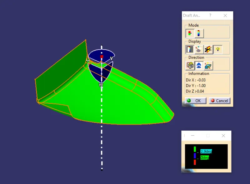
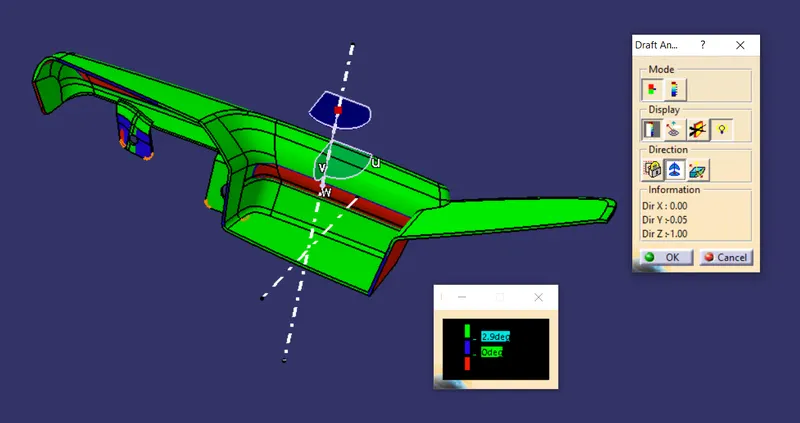
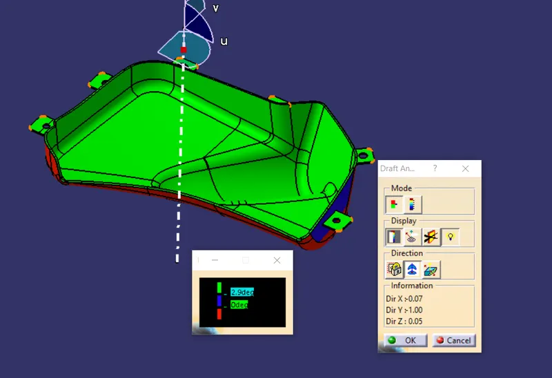
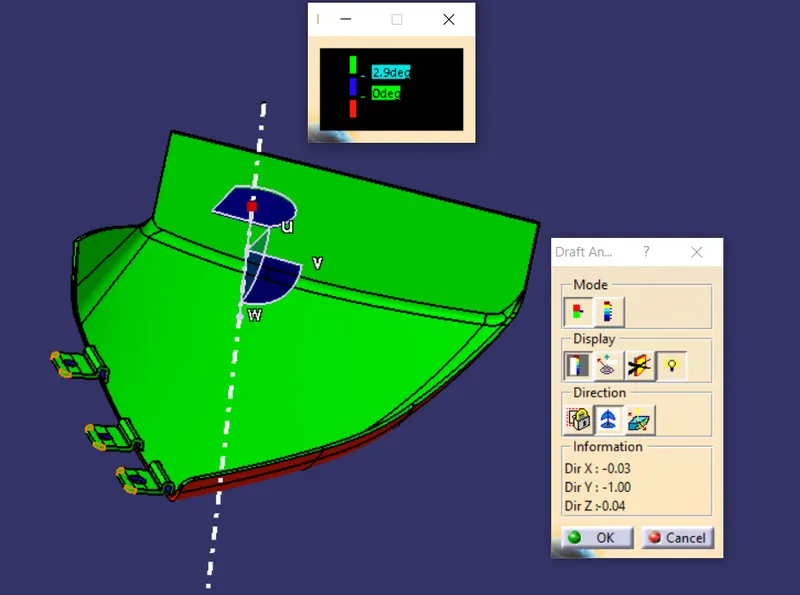
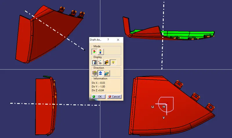
Here the surfaces which has less than 3 degree of draft should be brought into the attention of Class A designer.
Map Pocket
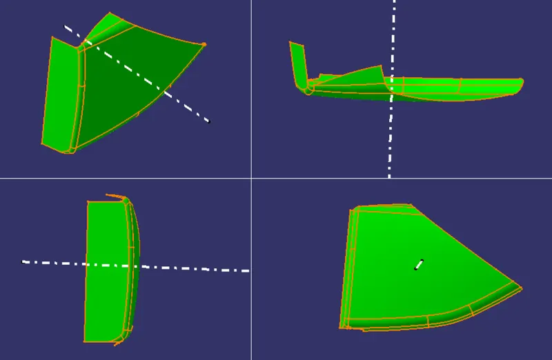
CREATION OF CLASS B & C SURFACE:
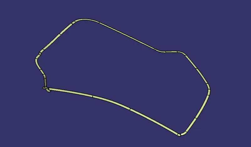
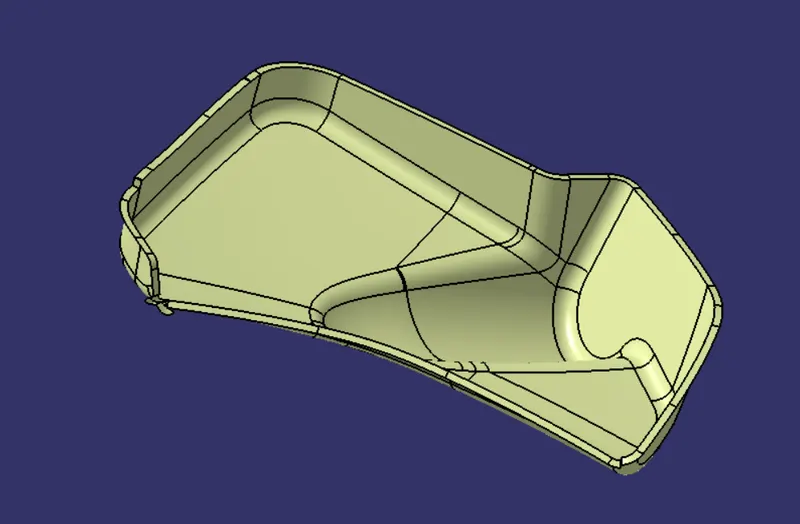
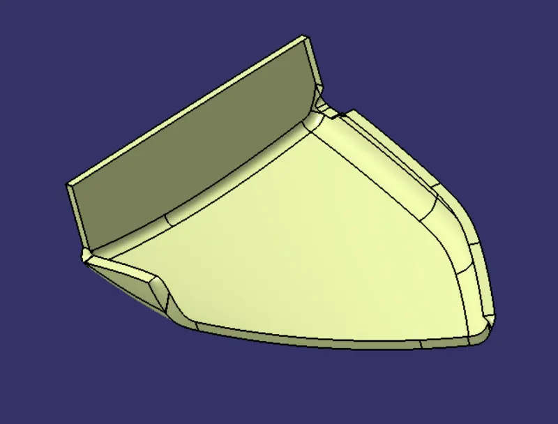
The class A surface is directly offsetted to 2.5 mm and the boundaries of it are extrapolated.The thickness value is measured from the respective master sections.
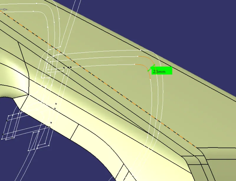
Arm Rest:
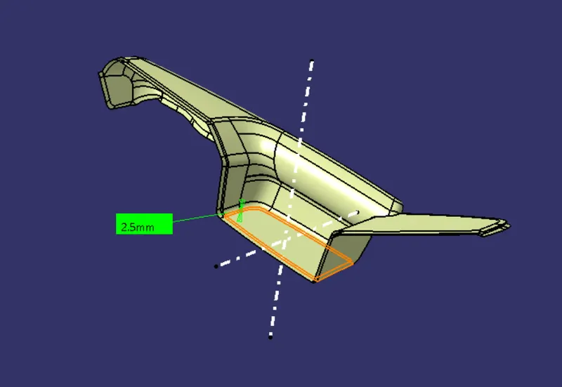
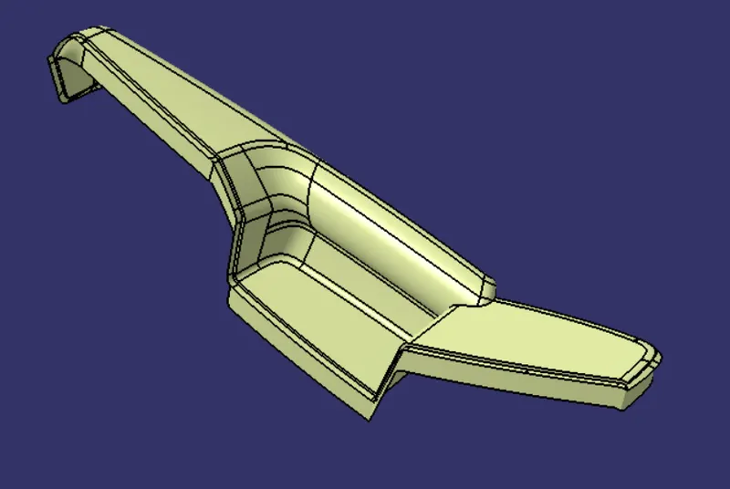
The C surface is then created along the tooling direction and some of the areas are created using multi section and later joined together with the class A.
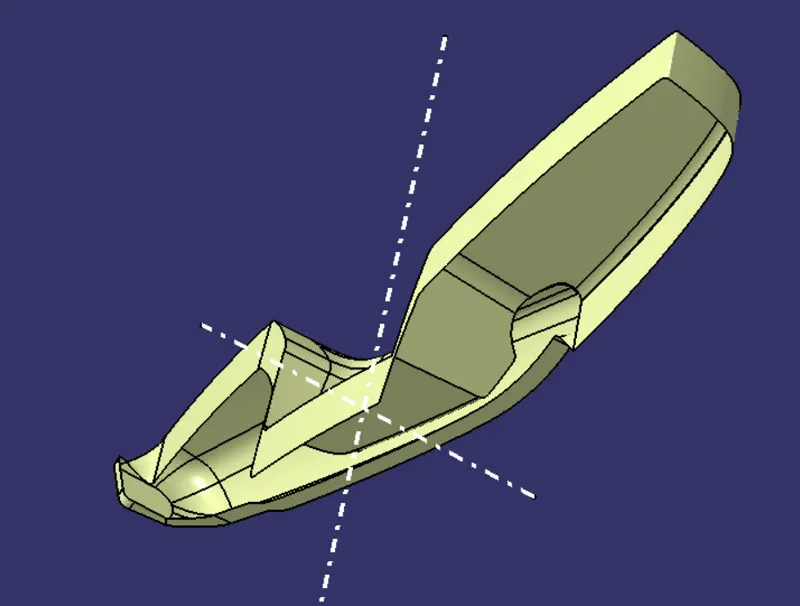
Lower Substrate:
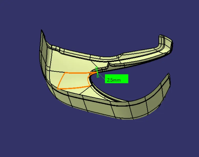
The C surface of the lower substrate is created 90 deg w.r.t. the A surface and on some areas it is swept at 3 deg w.r.t the tooling axis.Then it is joined together for the final trim.
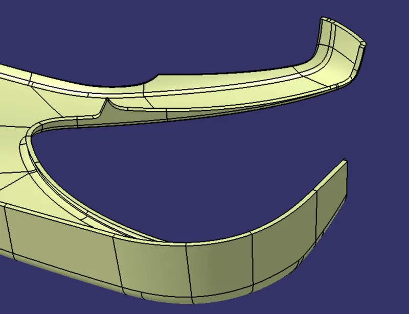
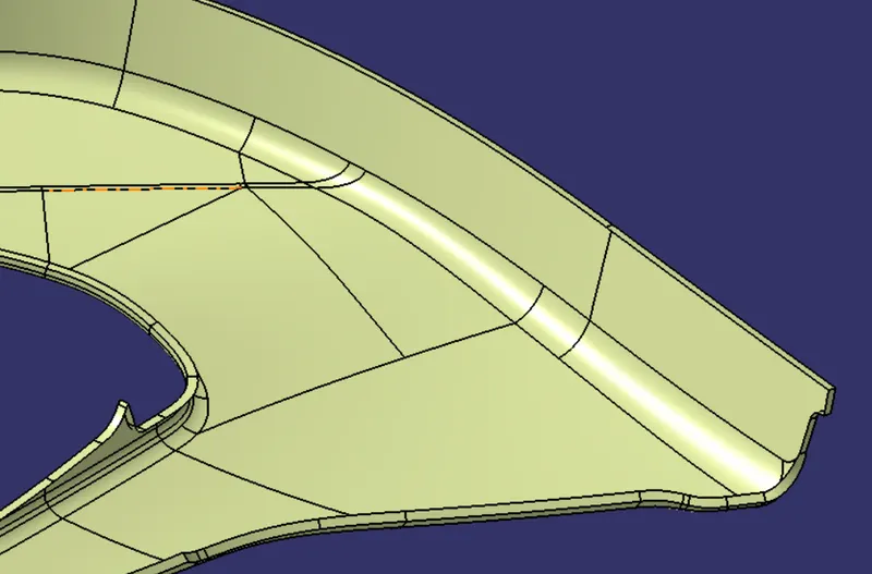
Bottle Holder:
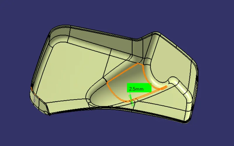
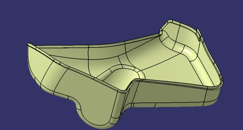
The C surface is created at 90 deg w.r.t the A surface and it is later joined with the A surface.
Map Pocket:
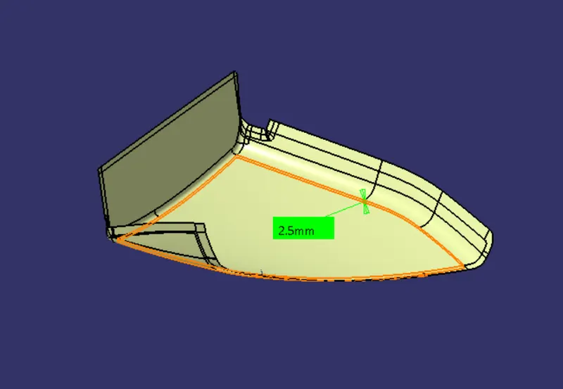
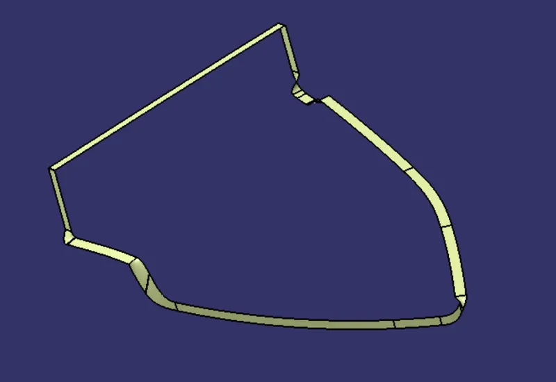
The C surface is created and it is later joined with the A surface.
FINAL TRIM:
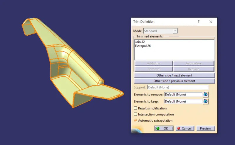
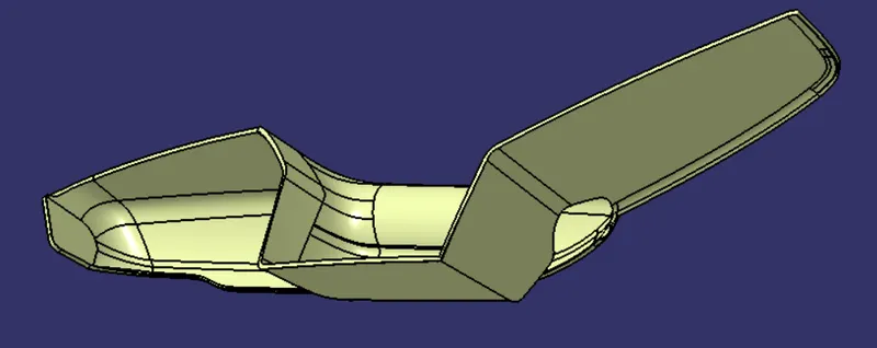
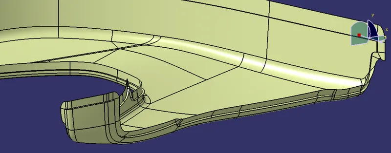
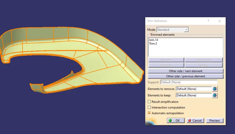
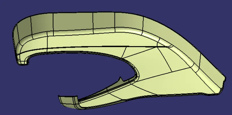
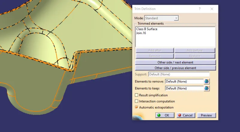
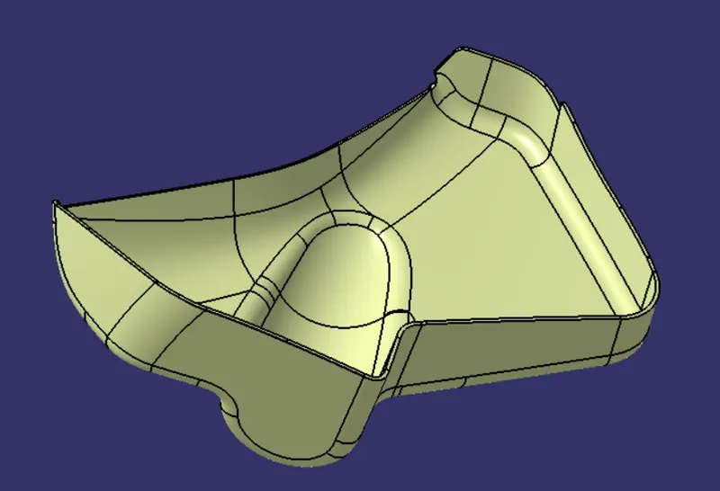
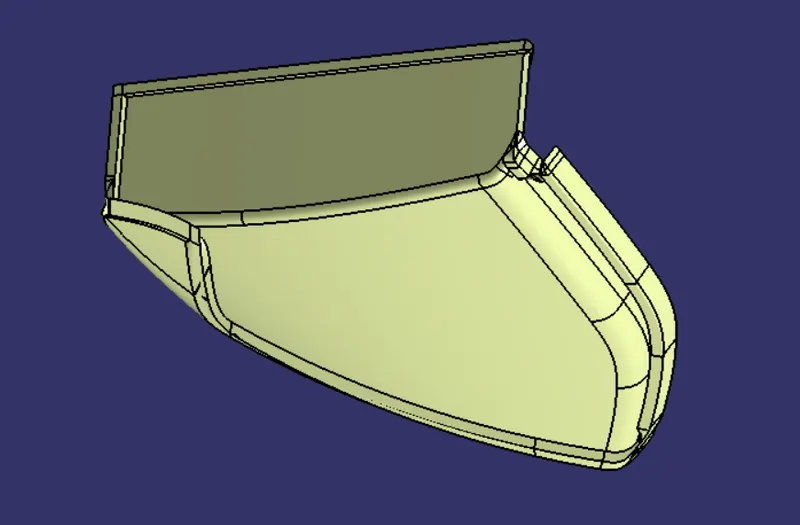
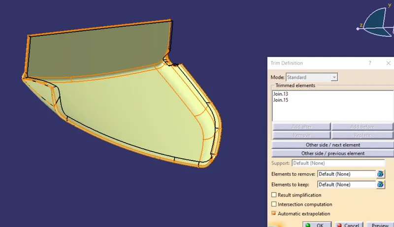
The C surface which is joined with the class A surface is trimmed with the B surface to get a closed body.
Arm Rest:
Lower Substrate:
Bottle Holder:
Map Pocket:
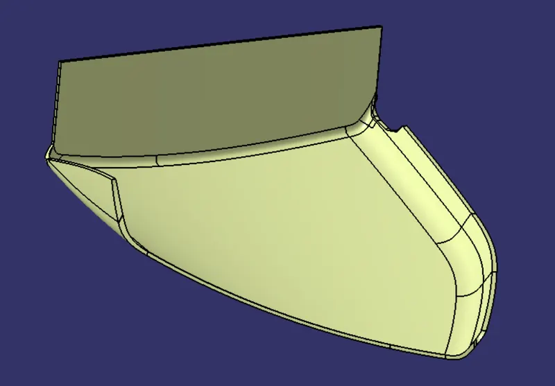
SOLID BODY:
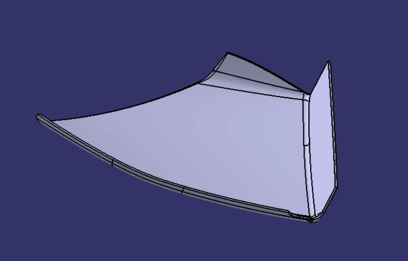
Now a solid body is created using the closed surface command.
Arm rest:
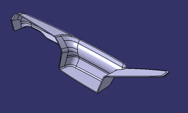
Lower Substrate:
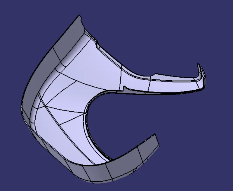
Bottle Holder:
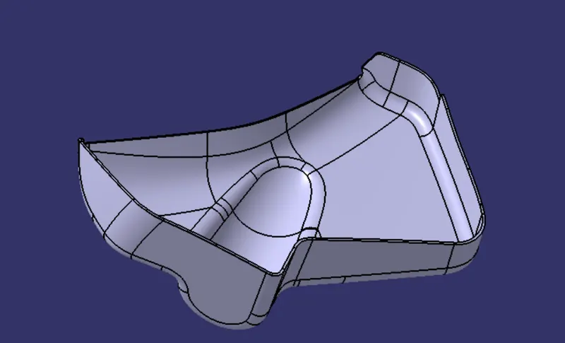
Map Pocket:
B SIDE FEATURES:
Following the master section,B side features such as heat stakes,dog house,ribs,locators and flanges are created respectively.
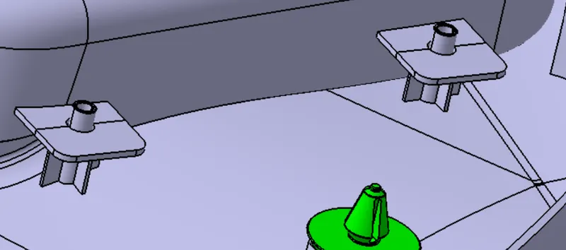
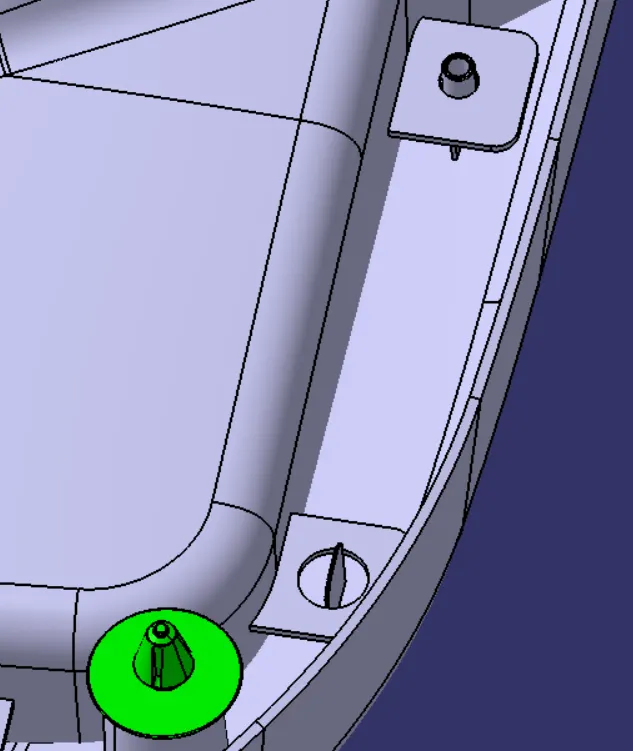
Looking into the master section heat stakes are located on the lower substrate at required areas.Ribs are also created for additonal support to the heat stake as well as to support the flanges.Locators are created to constrain the DOF of the component for assembly purpose.Dog houses are created to mount the push pin which is given in the input.
- Min draft of 0.5 is given to the heat stakes as well as the ribs which supporting it.
- Min radius of 0.2 is given for both heat stake and ribs.
- Rib thickness is said to be 40 percent of the part thickness(2.5 mm) - 1mm
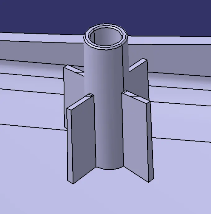
- Min draft of 0.5 degree is given for the locators and min radius of 0.2 is applied.
- Thickness is considered as 40 percent of the main body thicjness(2.5 mm) - 1mm.
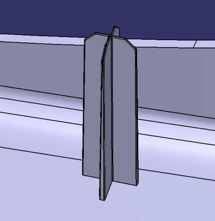
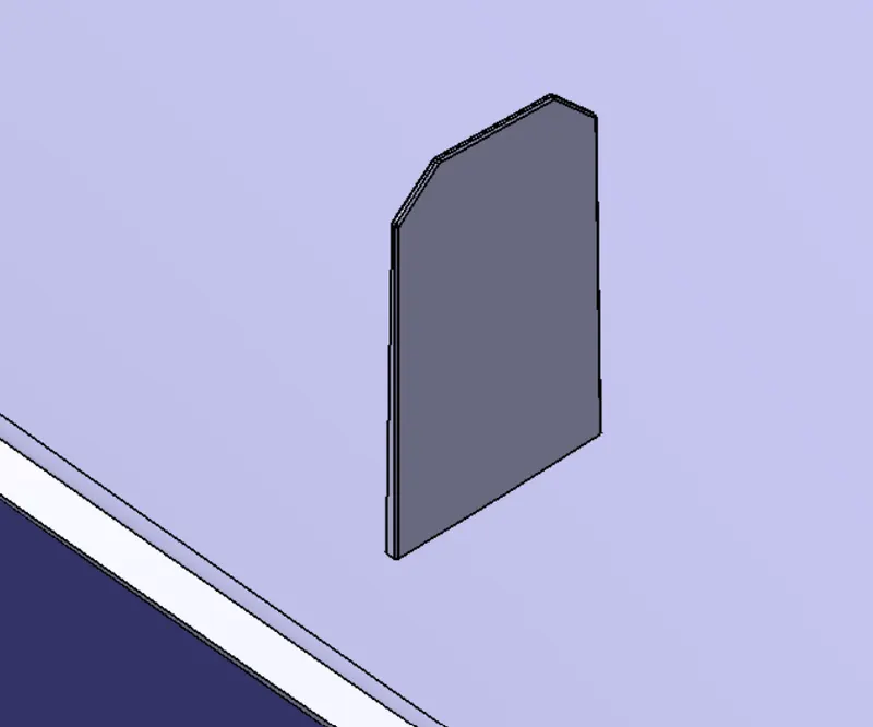
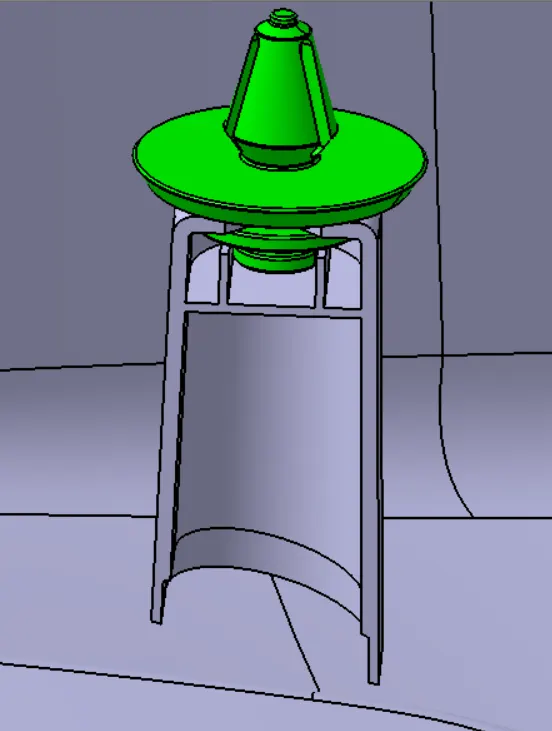
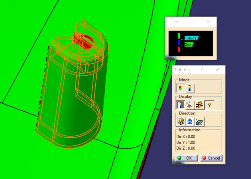
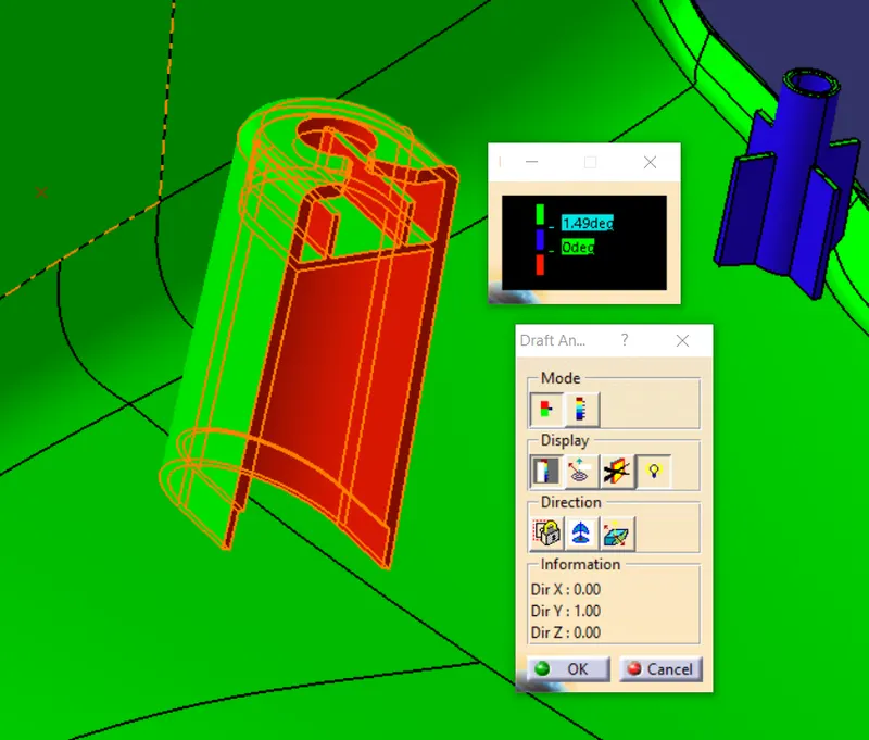
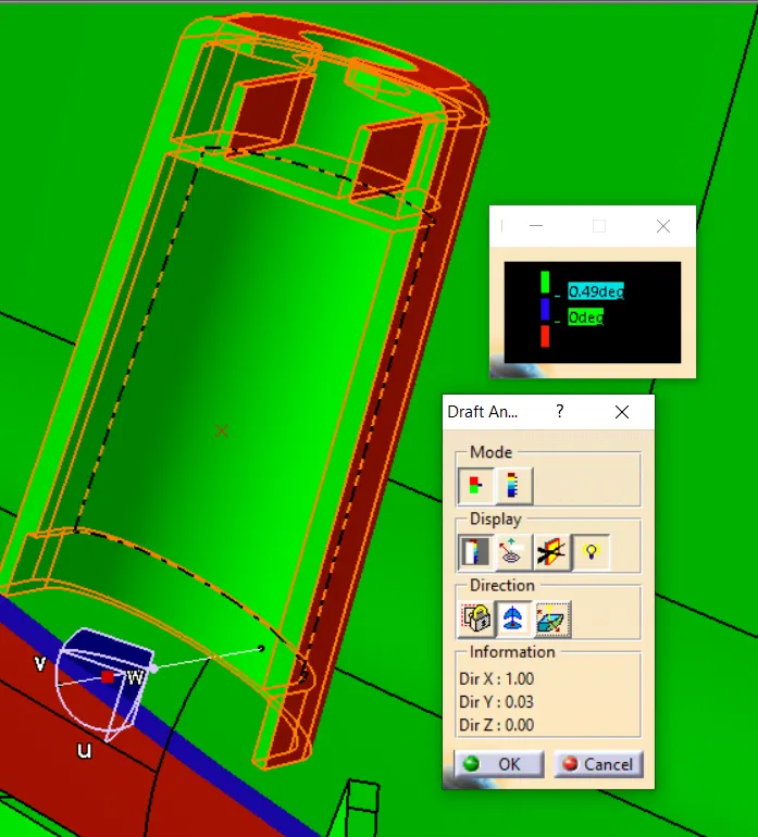
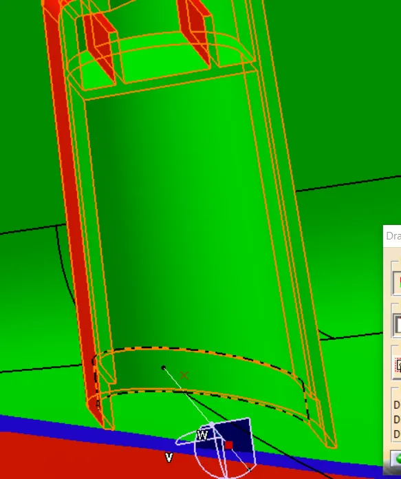
- 1.5 degree of draft is given outside the dog house and min of 0.5 degrees of draft is given inside the dog house.
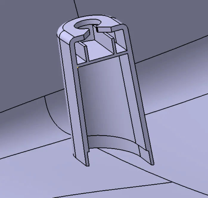
Dog House is created following the given input
Cut outs are made on top of the dog house for the push pin to get assembled on it.
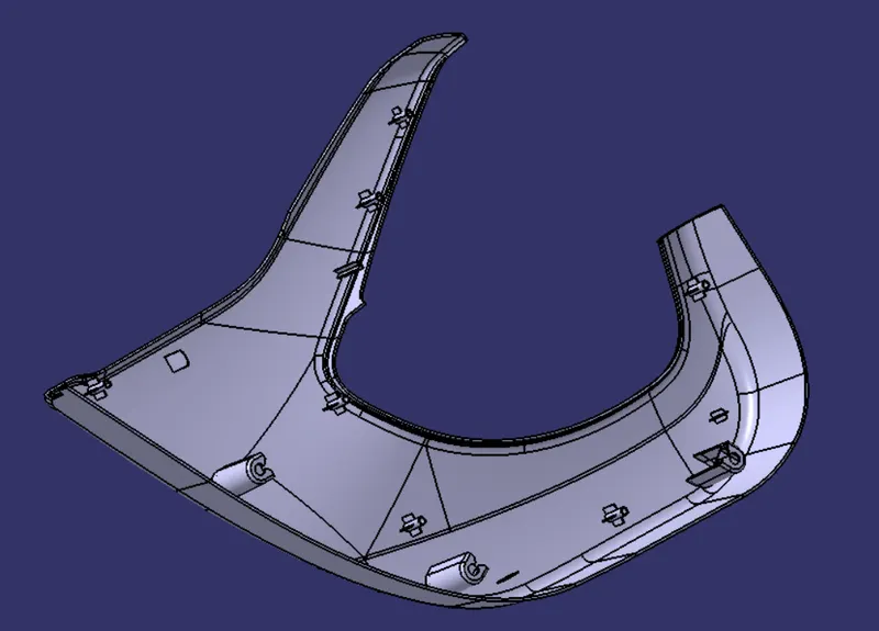
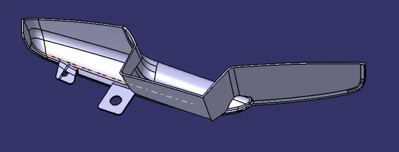
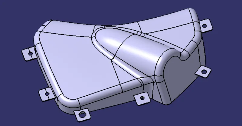
Now flanges are created accordingly on the arm rest,bottle holder and map pocket.
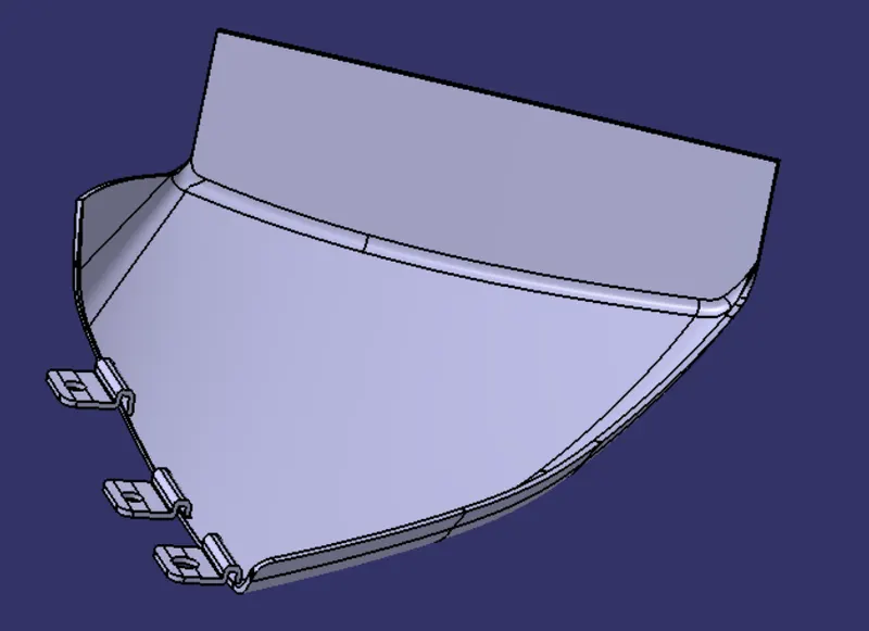
SECTION VIEW W.R.T MASTER SECTION:
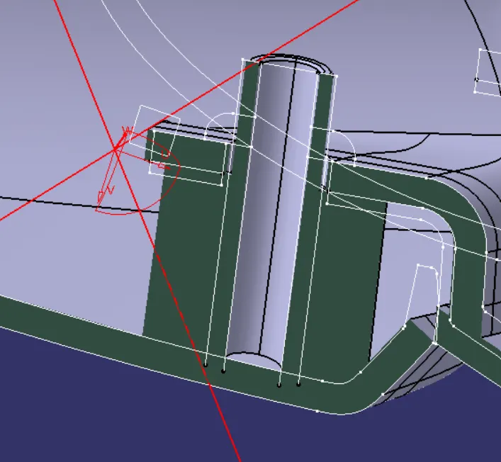
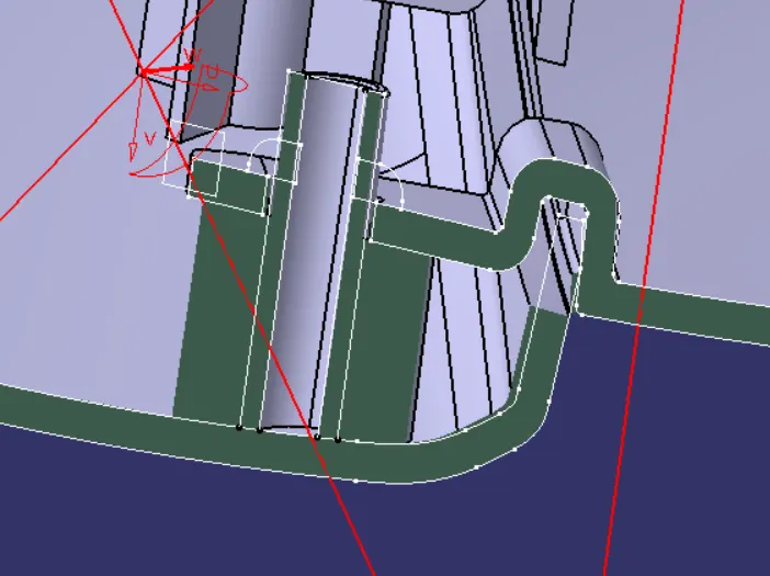
FINAL OUTPUT:
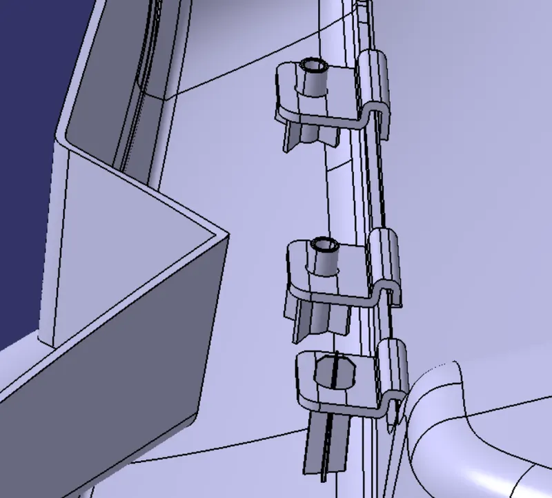
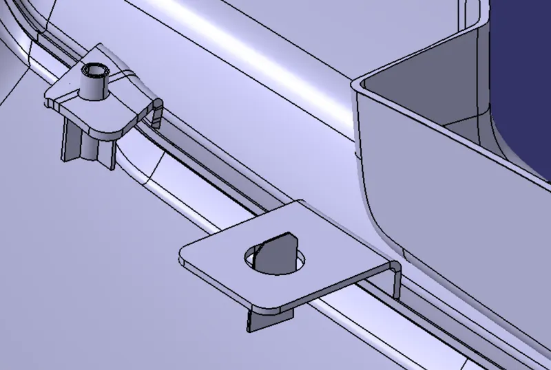
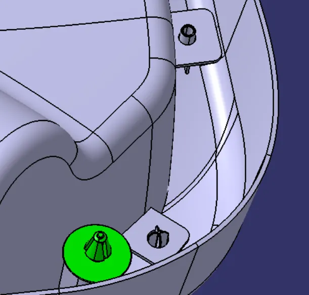
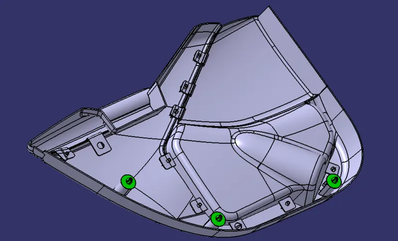
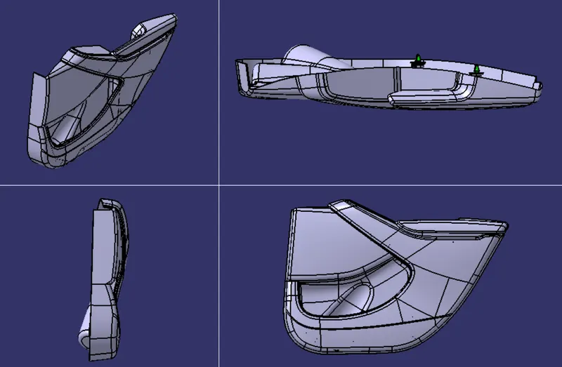
Push pin is assembled onto the dog house using coincidence assembly constraint. Push pins are explicitly introduced to help the door trim to get attached to the sheetmetal component of the door(BIW).
VARIOUS ORIENTATIONS:
ISOMETRIC VIEW:
FRONT,TOP & SIDE VIEWS:
DRAFT ANALYSIS:
ARM REST:
MAIN TOOLING
SIDE CORE
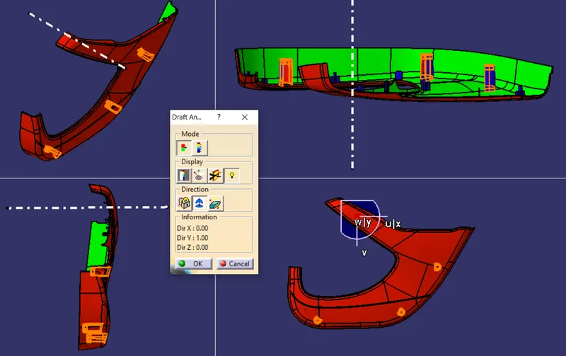
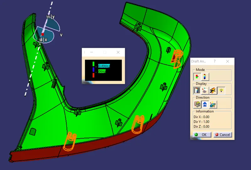
LOWER SUBSTRATE:
MAIN TOOLING AT 2.9 DEG:
MAIN TOOLING AT 0.49 DEG:
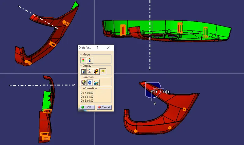
DOG HOUSE
MAIN TOOLING AT 1.49 DEG:
LIFTER AXIS AT 0.49 DEG:
BOTTLE HOLDER:
TOOLING AXIS AT 2.9 DEGREE:
MAP POCKET
TOOLING AXIS AT 2.9 DEGREE:
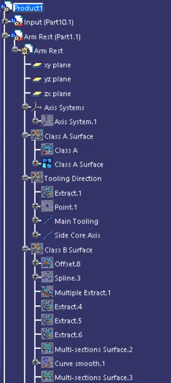
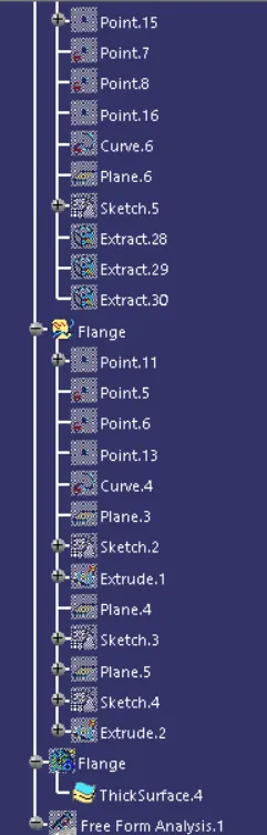
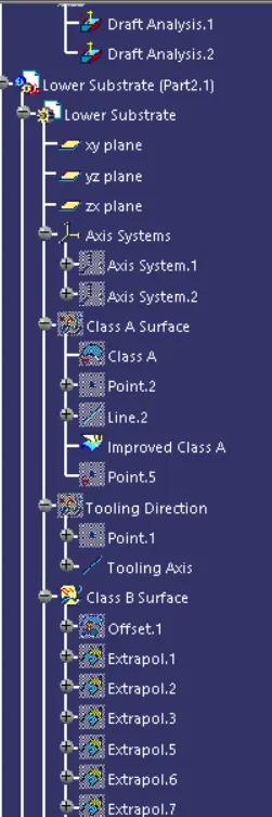
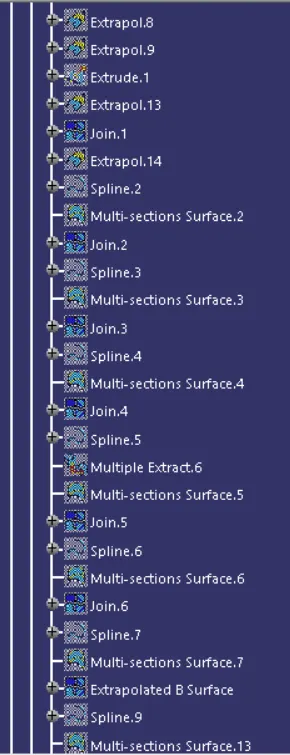
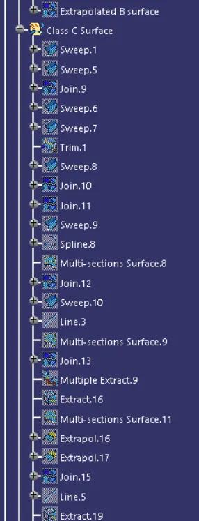
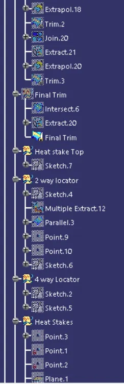
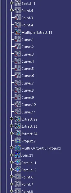
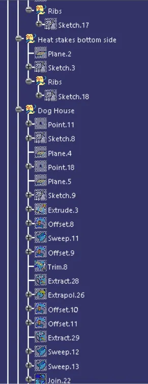
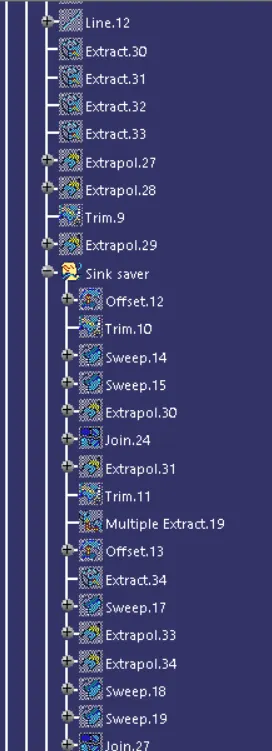
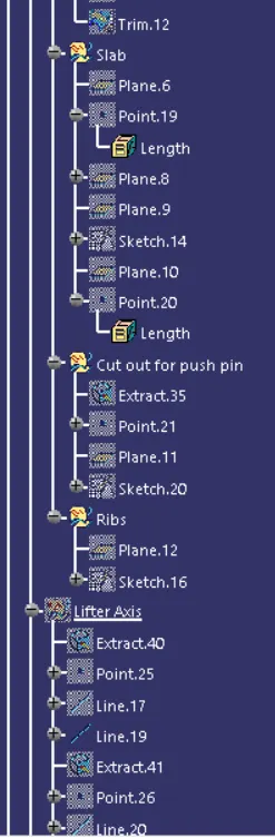
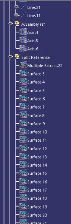
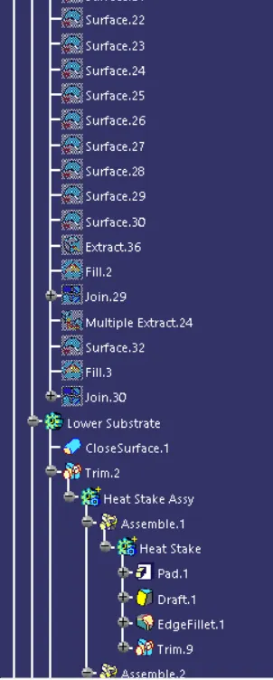
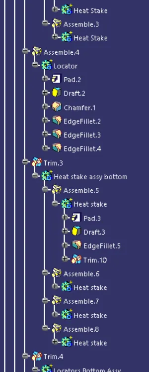
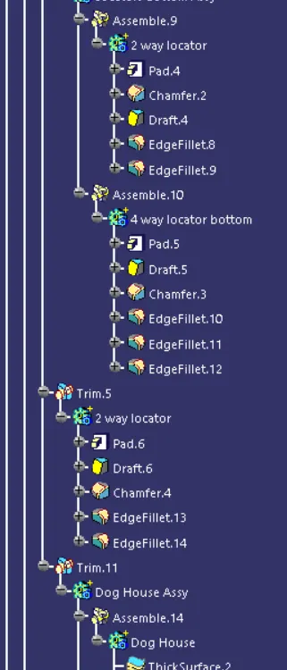
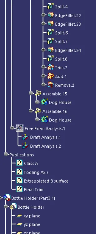
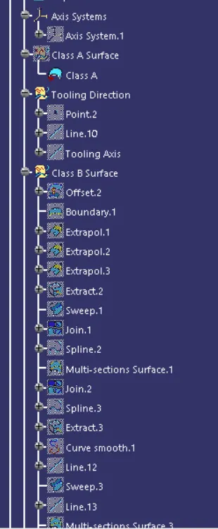
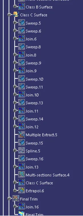
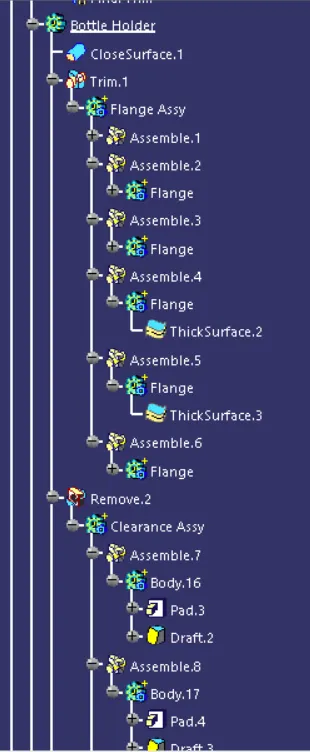
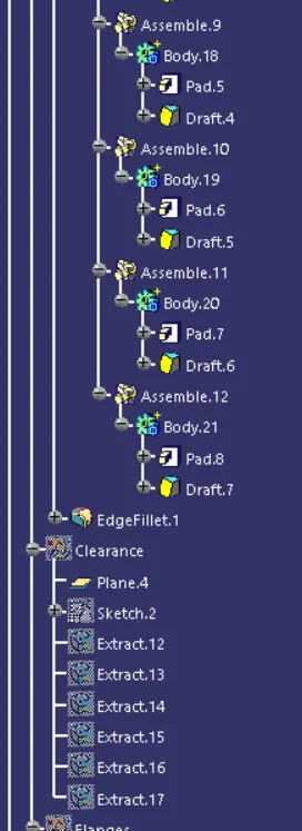
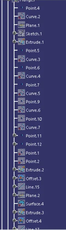
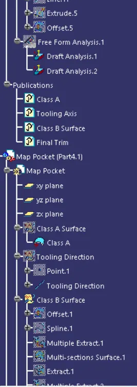
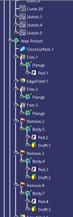
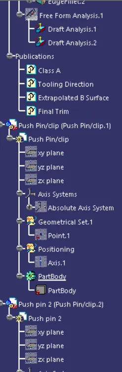
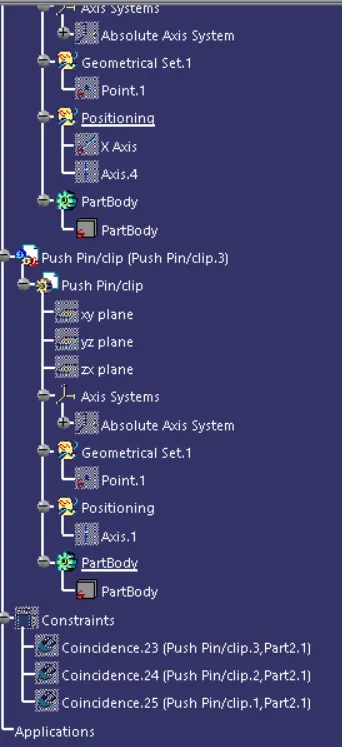
TREE STRUCTURE:
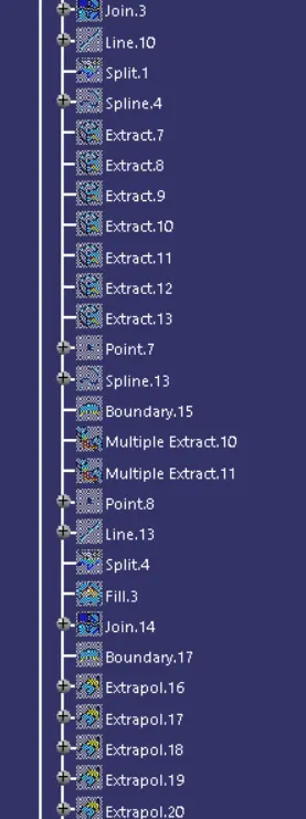
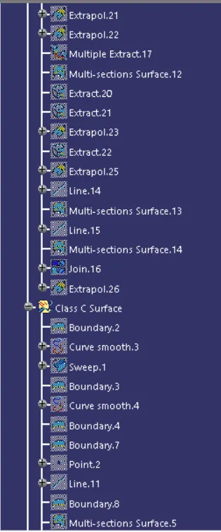
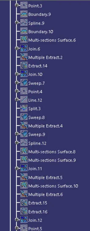
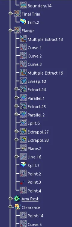
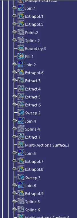
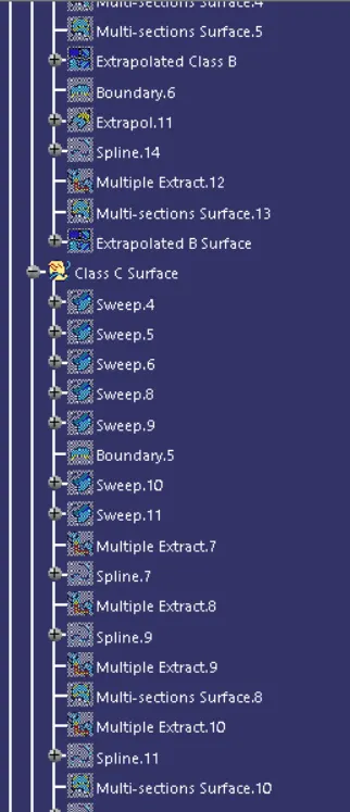
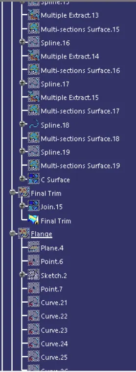
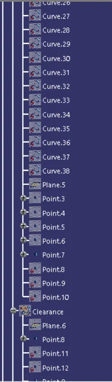
CONCLUSION:
To conclude the door trim panel is designed with respect to the master section given including all the engineering features in it following the plastic design rules.
Software used : CATIA