Week 11 - Final project
AIM: to create door trim panel with attachments while considering all the engineering rules and standards
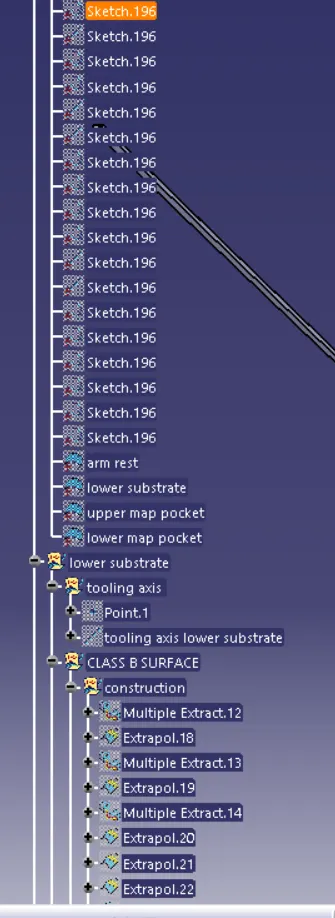
CREATING LOWER SUBSTRATE :
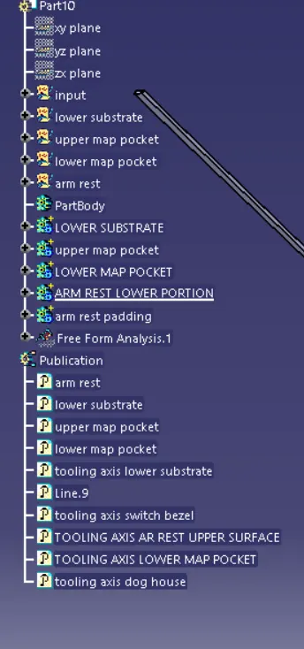
- TOOLING AXIS:
The tooling axis needs to be created in order to capture most of the region/part of the surface. generally tooling axis is created perpendicular to the surface
we have to create the tooling direction in the y-direction. First, create a point on the lower substrate surface, then create a line using that point in y-direction change the appearance and name it as tooling axis lower substrate.
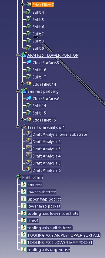
at last, publish the tooling axis
- DRAFT ANALYSIS :
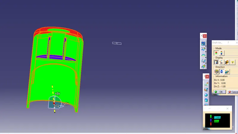
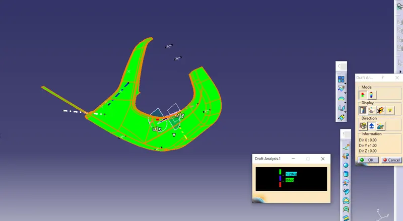
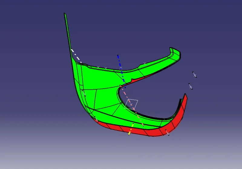
Draft analysis of class a surface has to be performed in order to check if the tooling axis we created is correct or not
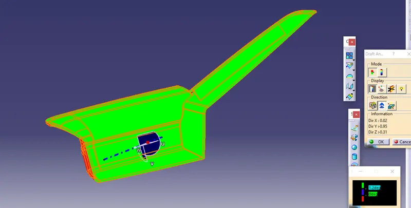
select the compass option and then place the compass on the tooling axis and click on the surface. Flip the direction if needed.
- CLASS B SURFACE :
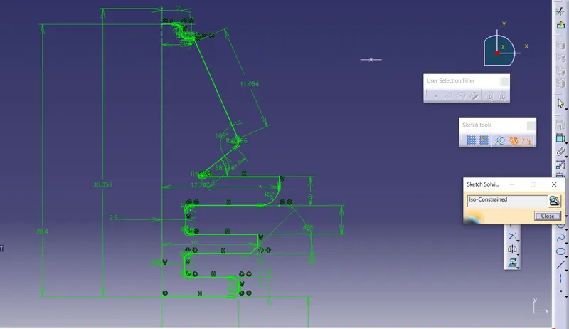
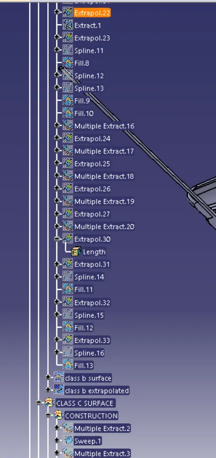
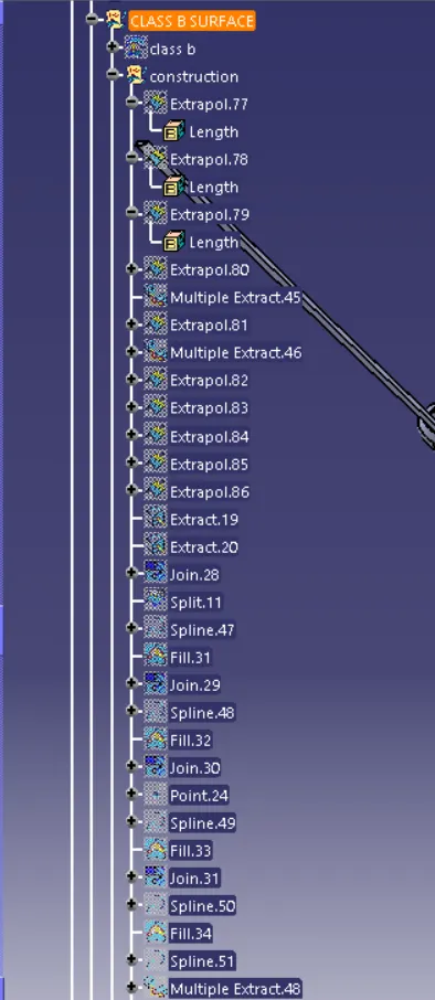
to create the class b surface we had to offset the class a surface with an offset of 2.5 mm ( thickness of the surface is measured using the given master section )
if an error occurs during the offset of the surfaces from class a surface then fix the surfaces before going to next step
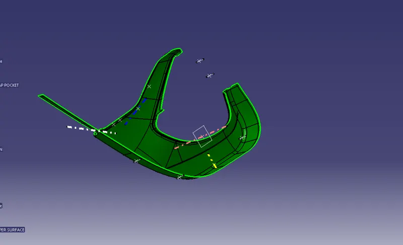
- CLASS C SURFACE :
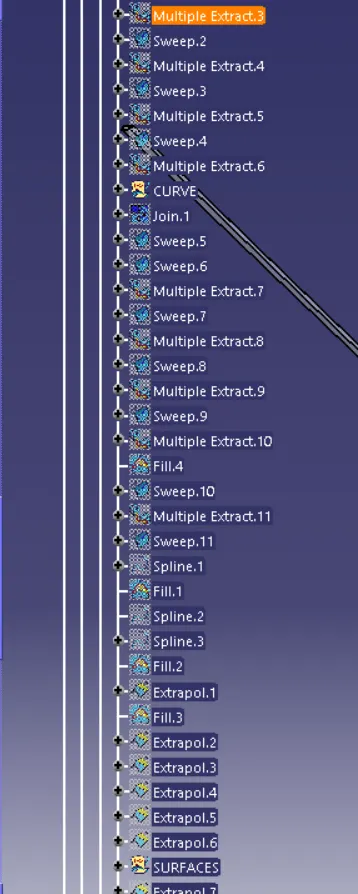
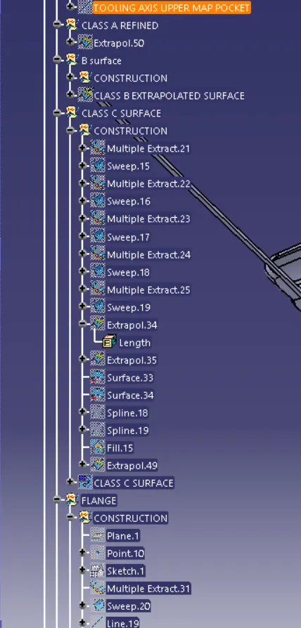
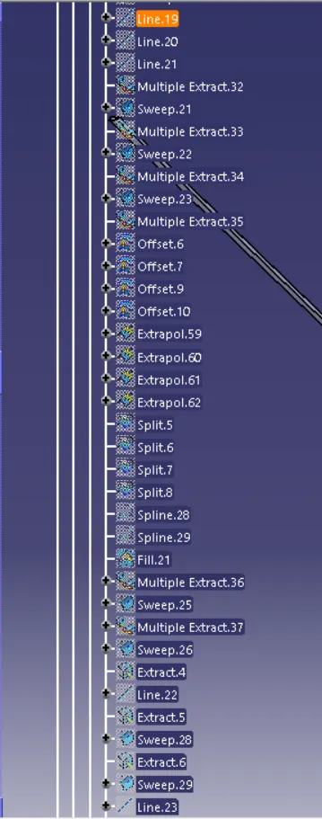
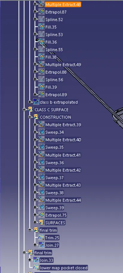
class c surface has to be created in order to close the lower substrate body . the create the class c surface multi extract the edges of the class a surface and then sweep them with the corresponding surfaces in an outward direction
fill the missing surfaces in between and trim the surfaces with each other to form a closed loop
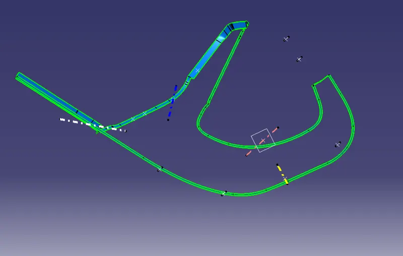
- FINAL TRIM LOWER SUBSTRATE :
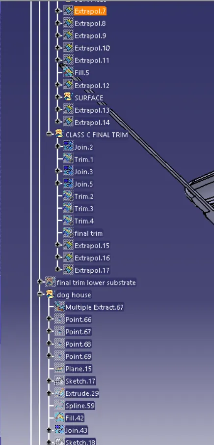
join the class a surface with the class c surface and then trim the new joined surface with the glass surface and form a closed lower substrate surface
check if there are any open edges on the body by using the boundary option if there isn't any then make a solid body out of it
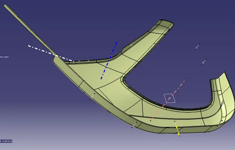
- SOLID-BODY :
to create a solid body first go to part body then add a new body rename it as lower substrate and then select the closed surface option .
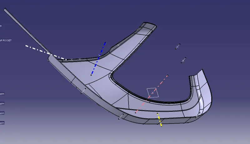
draft analysis of solid body
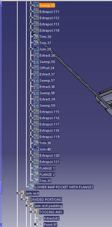
MAP POCKET
upper map pocket :
- TOOLING AXIS :
create a point on the surface of the upper map pocket and then create a line through that point in the y-direction
rename it as upper map pocket tooling axis and change the appearance and publish it.
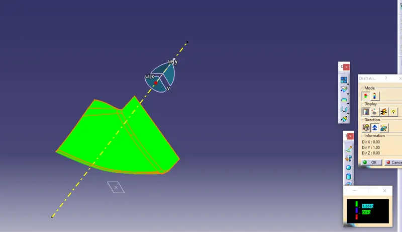
- DRAFT ANALYSIS :
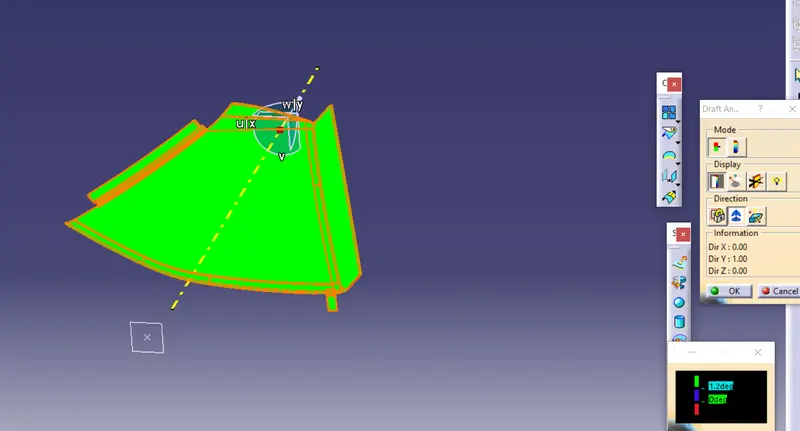
process for draft analysis is the same as done for the lower substrate repeated same steps to get the draft analysis
- CLASS A SURFACE:
multi-extract the given input
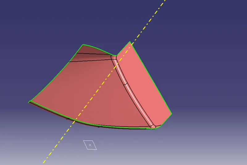
- CLASS B SURFACE :
offset the class a surface at an offset value of 2.5mm change the appearance if you want to check if all the surfaces are offsetted if not fix those missing surfaces
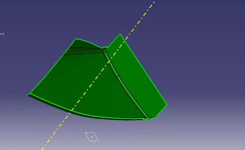
- CLASS C SURFACE :
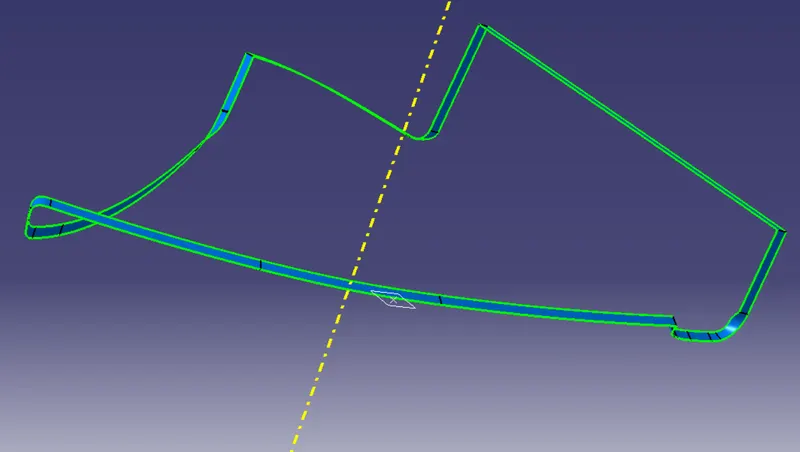
the process is the same, multi extract the edges of the class a surface and then sweep them with the corresponding support surface
join any gap in between the sweeps, and then trim them together to make a closed-loop
- FINAL TRIMMED SURFACE :
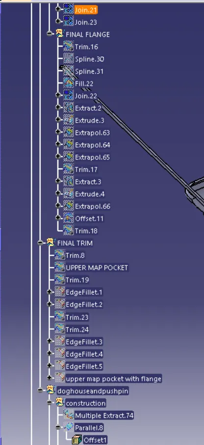
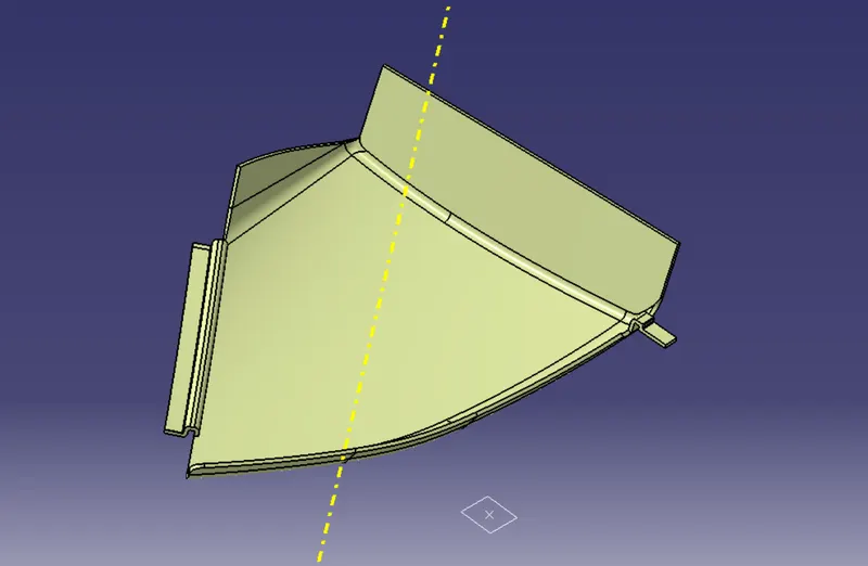
Join the class A surface with class C surface and then trim the joined surface with the class b surface
check if the surface is closed by using the boundary feature
- FLANGE :
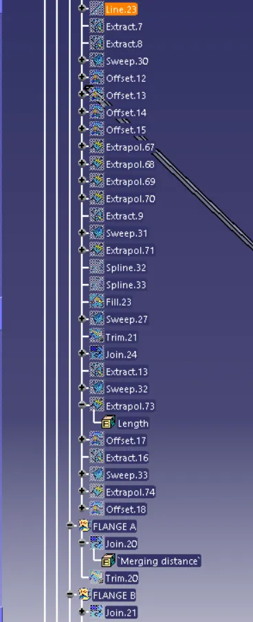
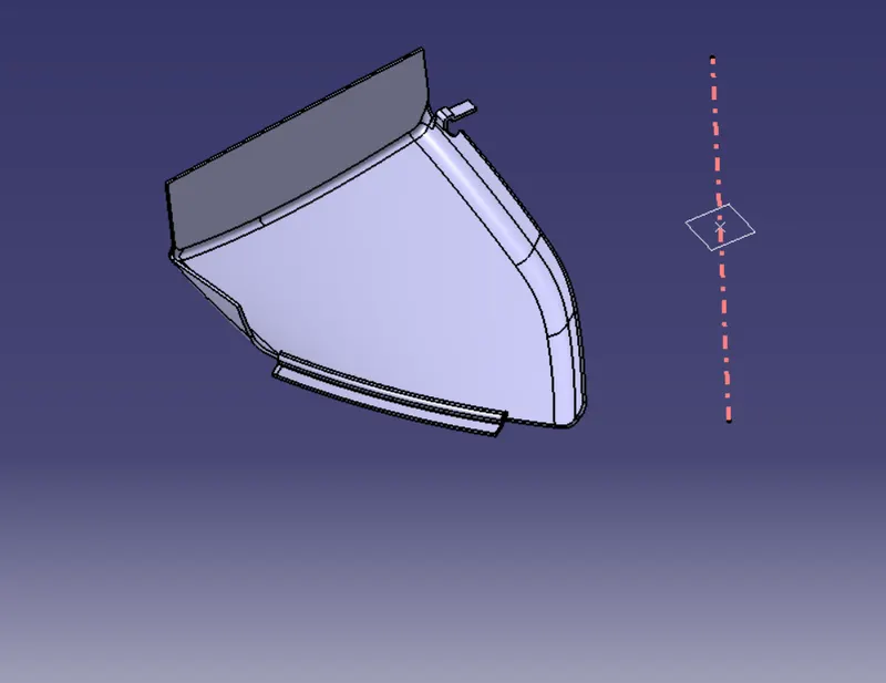
To create a flange first check the master section curves that are provided and then multi-extract and sweep the edge of the final surface that we create earlier .offset the sweep surface at a distance of 2.5mm. Create the edges of the flange by extracting the edges of the new swept surface . Trim the surfaces together and make a closed surface
- SOLID-BODY :
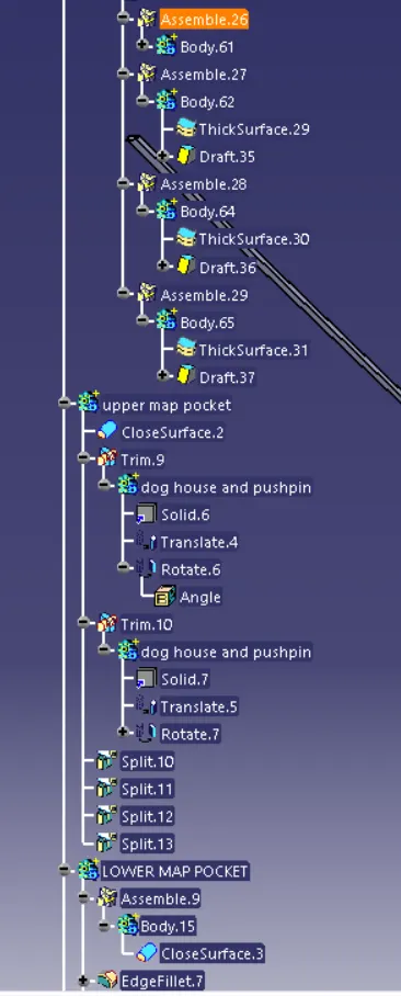
to create a solid body first go to the part body then add a new body rename it as upper map pocket and then select the closed surface option. add edge fillets where required measurements is taken from the given master section.
- DRAFT ANALYSIS ON SOLID BODY:
LOWER MAP POCKET
- TOOLING AXIS :
create a point on the surface of the lower map pocket and then create a line through that point in the y-direction
rename it as lower map pocket tooling axis and change the appearance and publish it.
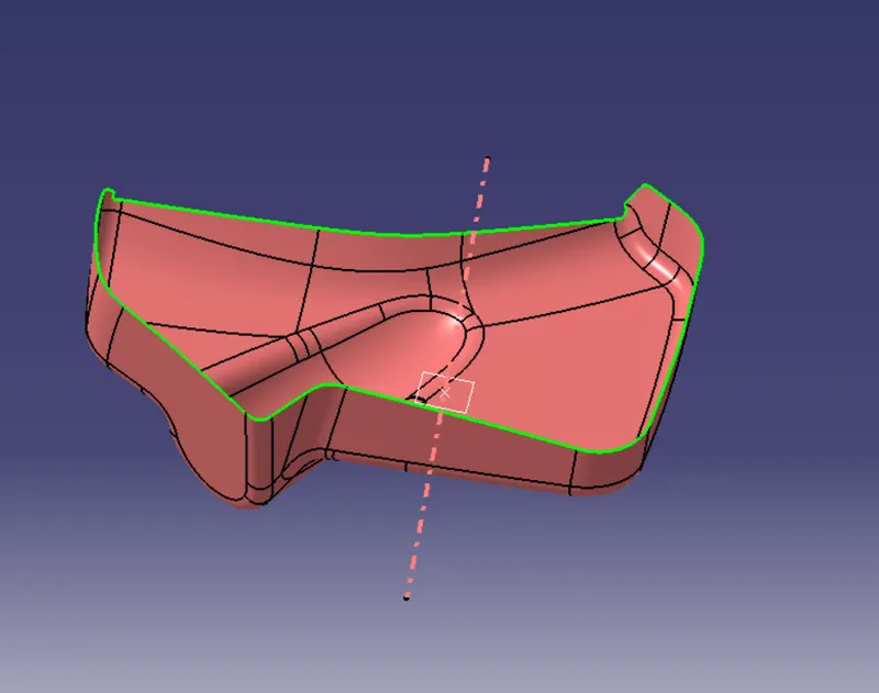
- DRAFT ANALYSIS :
process for draft analysis is the same as done for the lower substrate repeated same steps to get the draft analysis
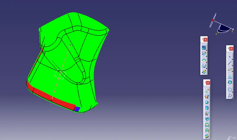
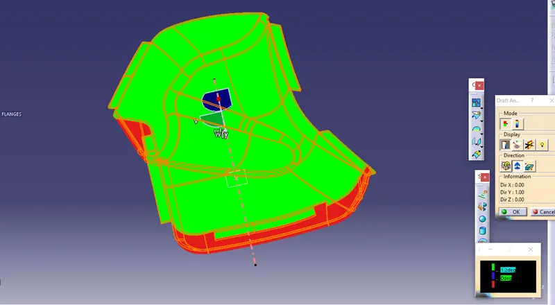
NOTE: SOME SURFACES OF THE CLASS A SURFACES ARE RED DURING THE DRAFT ANALYSIS WHICH NEEDS TO BE ADDRESSED TO THE CLASS A DESIGN TEAM
- CLASS A SURFACE:
multi-extract the given input
- CLASS B SURFACE :
offset the class a surface at an offset value of 2.5mm change the appearance if you want to check if all the surfaces are offset if not fix those missing surfaces
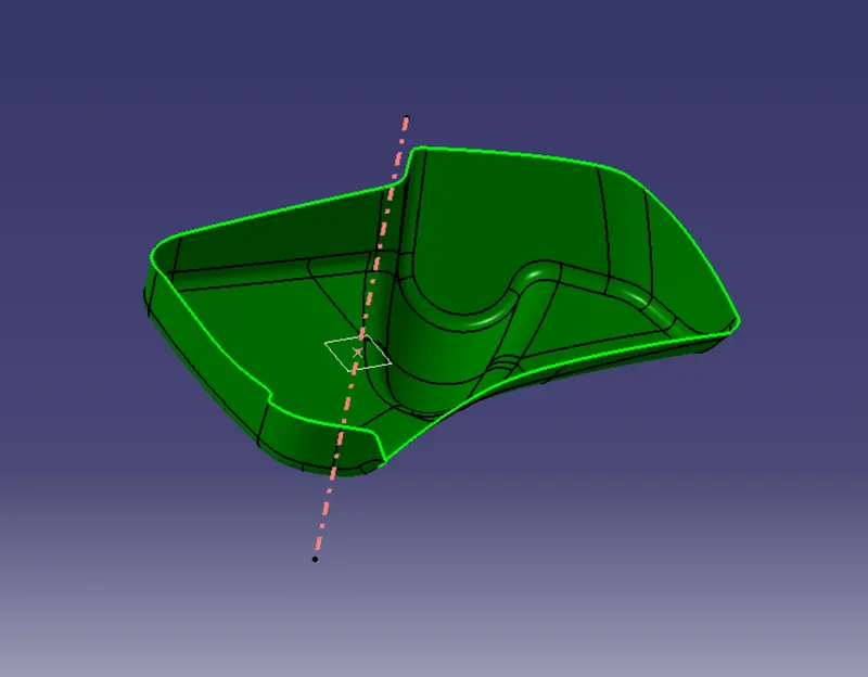
- CLASS C SURFACE :
the process is the same, multi extract the edges of the class a surface and then sweep them with the corresponding support surface
join any gap in between the sweeps, and then trim them together to make a closed-loop
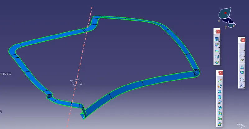
- FINAL TRIMMED SURFACE :
Join the class A surface with class C surface and then trim the joined surface with the class b surface
check if the surface is closed by using the boundary feature
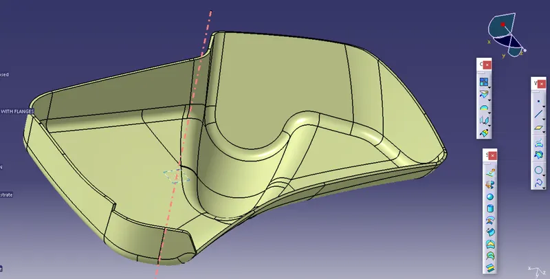
- FLANGE :
the process is the same as done for the lower map pocket To create a flange first check the master section curves that are provided and then multi-extract and sweep the edge of the final surface that we create earlier .offset the sweep surface at a distance of 2.5mm. Create the edges of the flange by extracting the edges of the new swept surface. Trim the surfaces together and make a closed surface
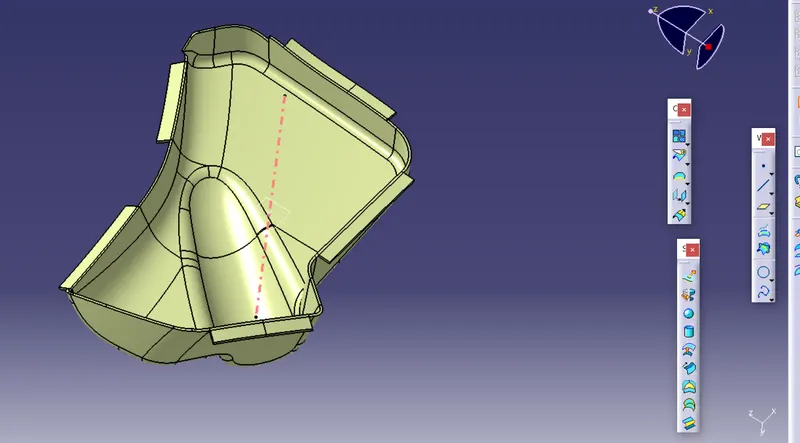
- SOLID-BODY :
to create a solid body first go to the part body then add a new body rename it as upper map pocket and then select the closed surface option. add edge fillets where required measurements is taken from the given master section.
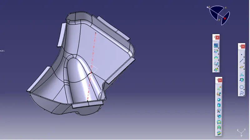
- DRAFT ANALYSIS ON SOLID BODY:
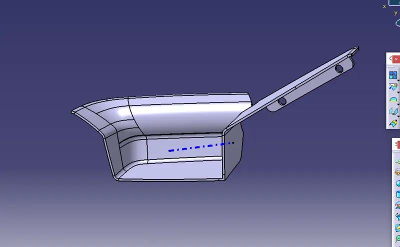
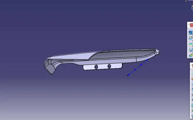
ARMREST
ARMREST PADDING :
- TOOLING AXIS :
create a point on the surface of the ARM REST PADDING and then create a line through that point in the y-direction
rename it as armrest padding tooling axis and change the appearance and publish it.
- DRAFT ANALYSIS :
process for draft analysis is the same as done for the lower substrate repeated same steps to get the draft analysis
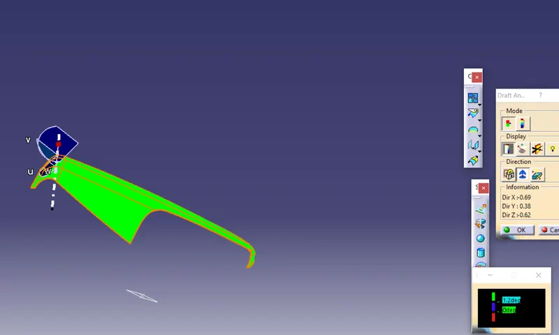
- CLASS A SURFACE:
multi-extract the given input
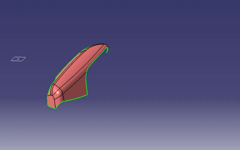
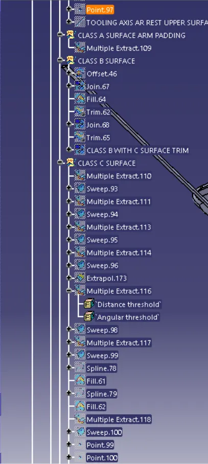
- CLASS B SURFACE :
offset the class a surface at an offset value of 2.5mm change the appearance if you want to check if all the surfaces are offsetted if not fix those missing surfaces
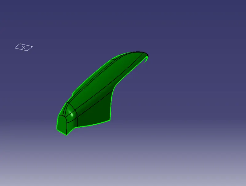
- CLASS C SURFACE :
the process is the same, multi extract the edges of the class a surface and then sweep them with the corresponding support surface
join any gap in between the sweeps, and then trim them together to make a closed-loop
in this case, class b is already trimmed with class b surface to fill the missing surfaces
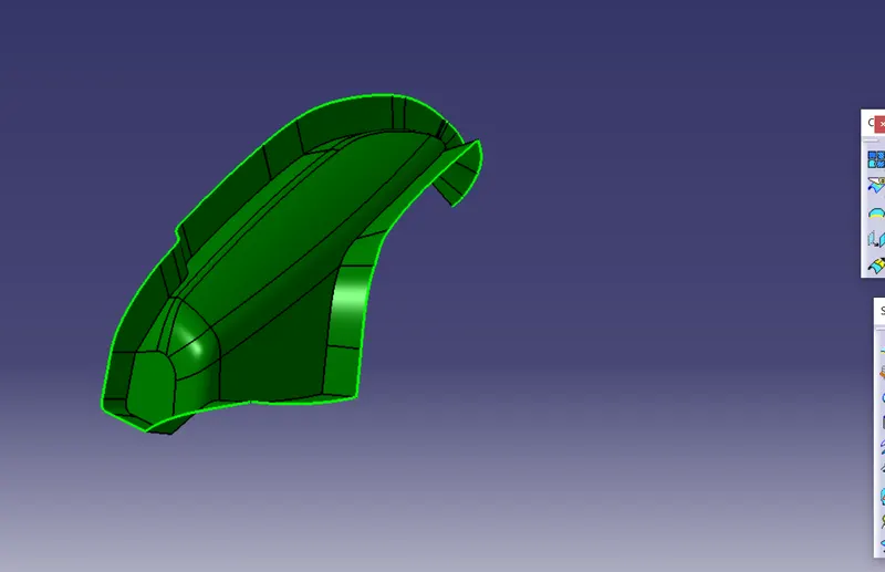
- FINAL TRIMMED SURFACE :
Join the class A surface with class C surface and then trim the joined surface with the class b surface
check if the surface is closed by using the boundary feature
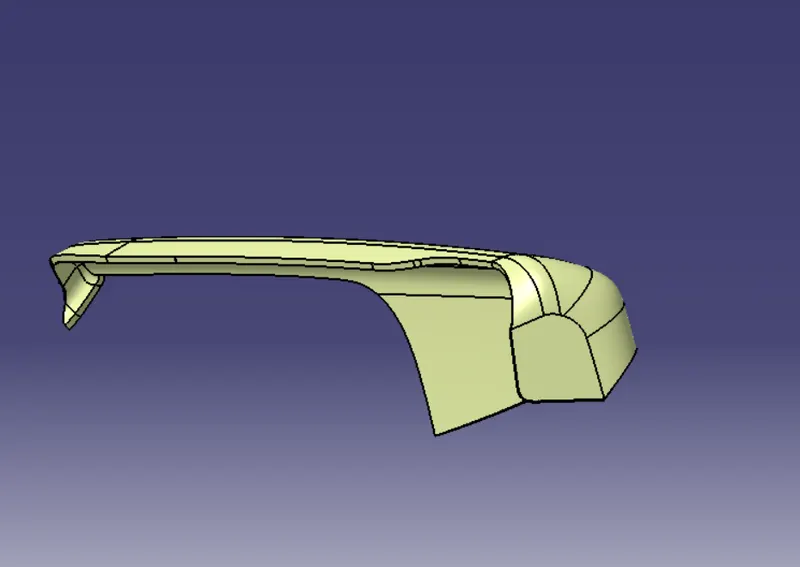
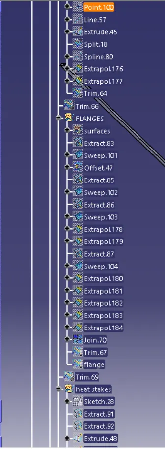
- FLANGE :
To create a flange first check the master section curves that are provided and then multi-extract and sweep the edge of the final surface that we create earlier .offset the sweep surface at a distance of 2.5mm. Create the edges of the flange by extracting the edges of the new swept surface . Trim the surfaces together and make a closed surface
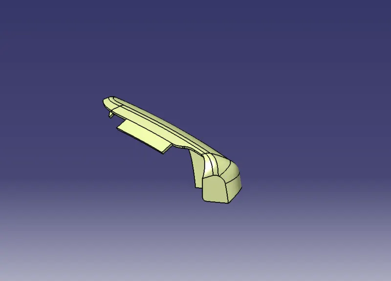
- SOLID-BODY :
to create a solid body first go to the part body then add a new body rename it as upper map pocket and then select the closed surface option. add edge fillets where required measurements is taken from the given master section.
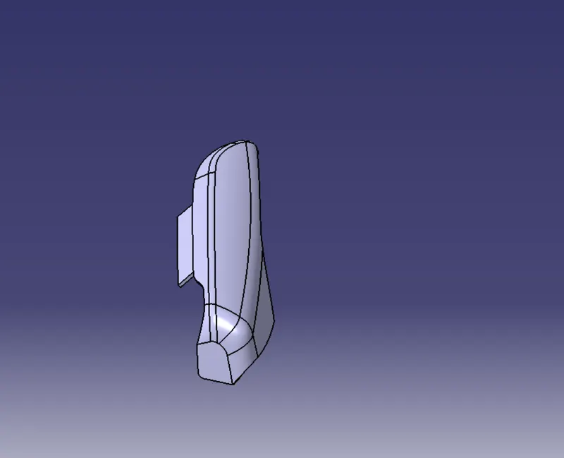
ARMREST LOWER PORTION
ALL THE PROCESSES ARE THE SAME AS THAT OF THE ARMREST PADDING PORTION
- TOOLING AXIS
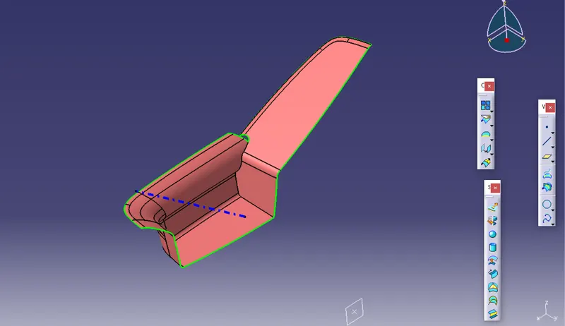
- DRAFT ANALYSIS
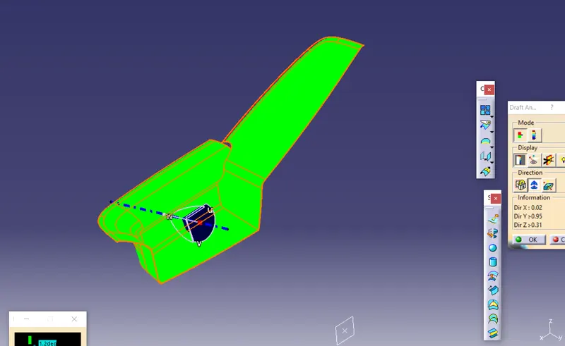
- CLASS A SURFACE
- CLASS B SURFACE
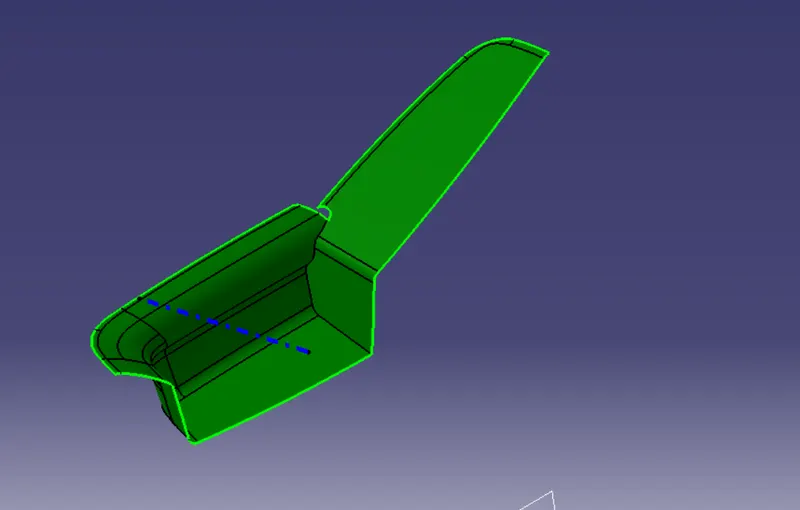
- CLASS C SURFACE
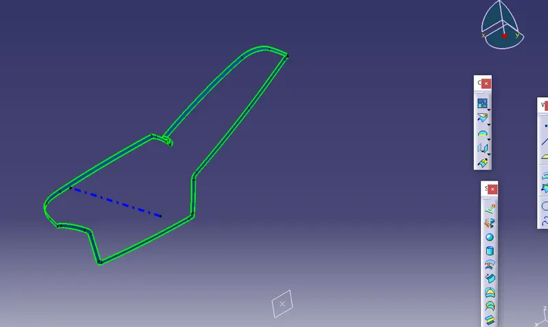
- FINAL TRIM
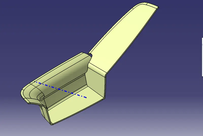
- FLANGE
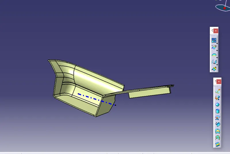
- SOLID BODY
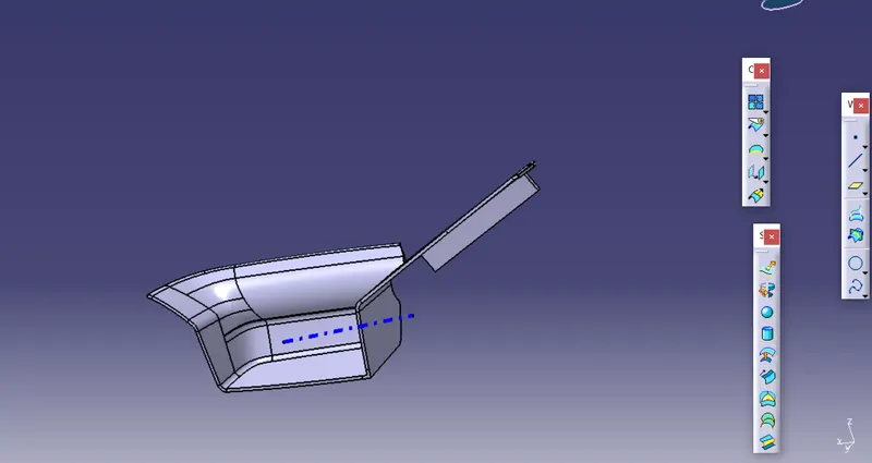
- DRAFT ANALYSIS ON SOLID BODY :
ATTACHMENT FEATURE:
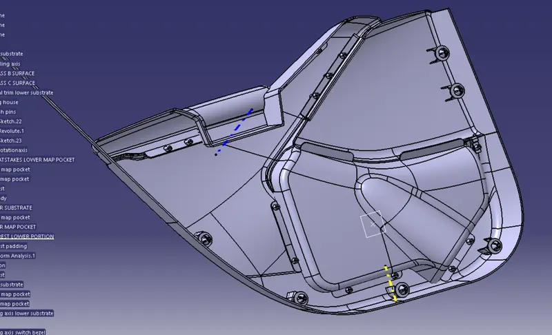
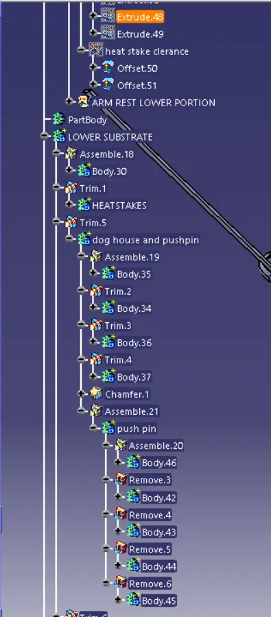
HEAT STAKES :
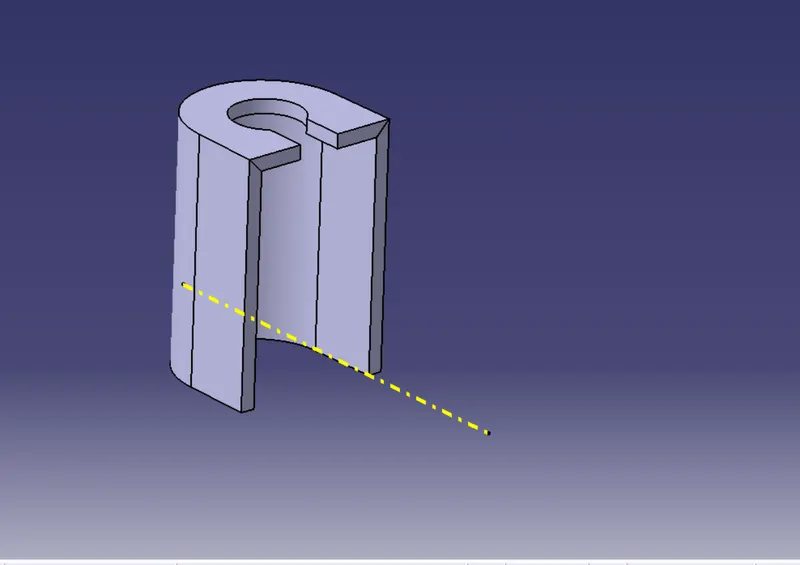
Heat Staking is a pulsed-heat process to join two or more parts out of which one at least is made of plastic. The process is to deform the plastic material using heat and force at a set process time. The bond is made by partially de-forming the plastic part in order to fix the other.
PROCESS :
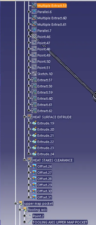
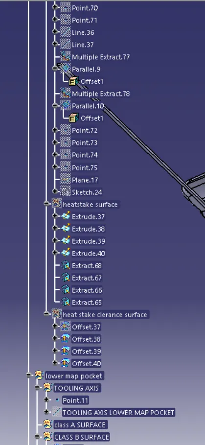
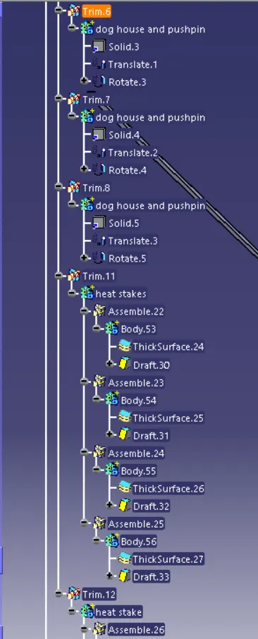
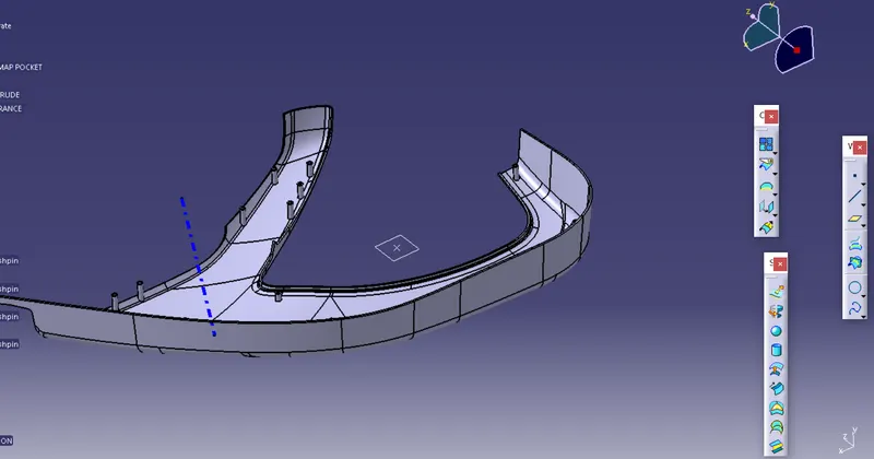
to create a heat stake we need to create a sketch on the surface where we need to make one, for that first extract the required surface and then use the parallel curve and offset the curve to a required distance, then make points on that curve
make the sketch corresponding to where we need heat stakes
extract the sketch and then extrude the surface one by one
make a new body and then add thickness to it ( 2mm ) add a draft of 0.5deg to it
union trim heat stakes from the required body that we already created
NOTE: WHILE EXTRUDING THE SURFACE MAKE SURE THAT THE DISTANCE BETWEEN THE TOP END OF THE HEAT STAKE EXTRUDED SURFACE AND THE FLANGE IS A MINIMUM OF 7 MM
HEAT STAKE CLEARANCE :
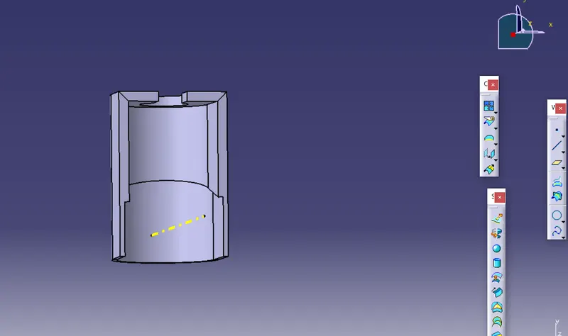
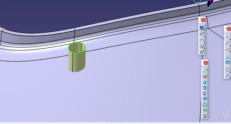
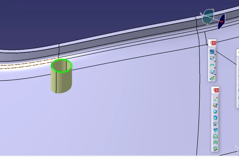
to create a clearance surface just offset the heastake extruded surface at an offset of 0.5
now split the solid body with the offset surface where heat stakes will be joining this need to be done on the flanges where heat stake will pass through or simply an opposite body of the heat stake joining
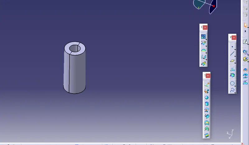
the inner cylinder is the heat stake surface and the outer is the clearance surface
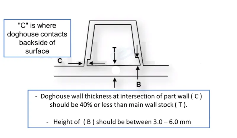
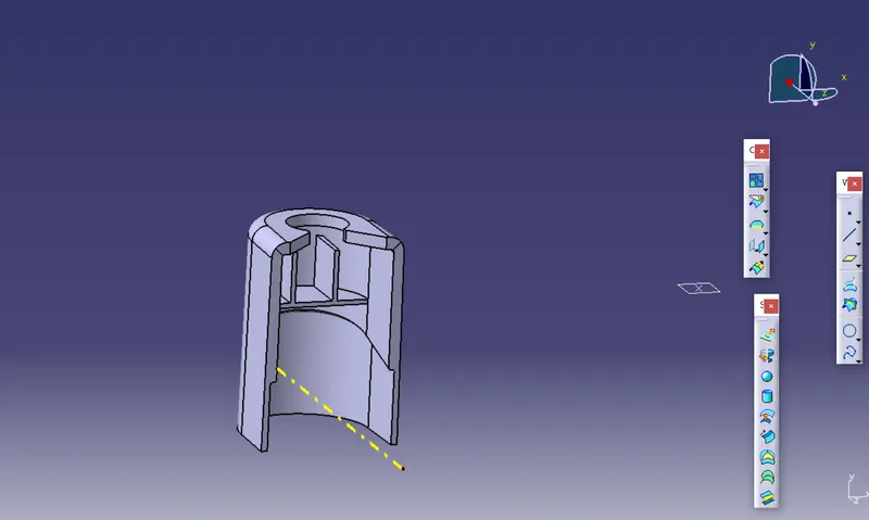
DOG HOUSE :