Week 11 - Final project
Door panel:
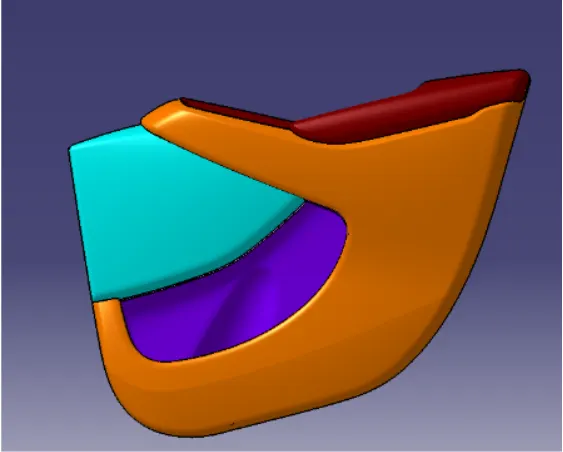
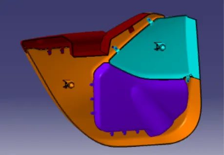
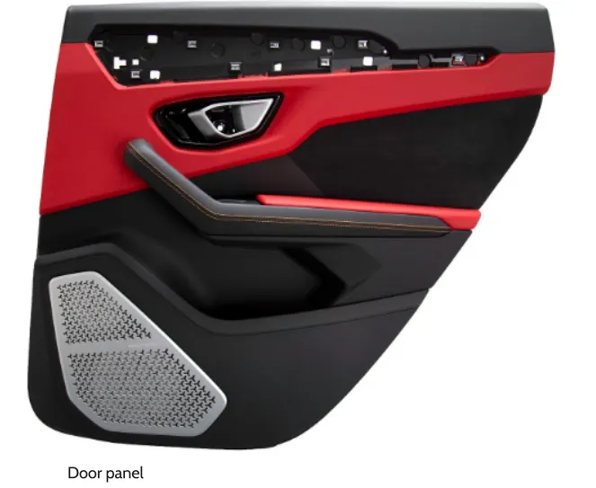
The door panel is the interface between the interior of the car and the inner workings of the door. Generally, the door panel is divided into parts for easy designing like the armrest, map pocket, lower substrate. These require one of the toughest requirements among the interior parts of the car. This should be designed to withstand the load while being less than 2mm in thickness and also to protect the occupants during collisions.
AIM:
We aim to create the B surface and C surface from the given Class-A surface and following the master section rules to design the B side features like flanges,
screw boss, dog house, push clips, heat stakes.
Class A surface:
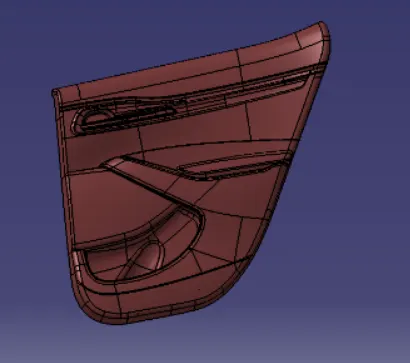
Class A surface is the surface that is visible to us physically. This term is specifically used in automotive fields. It is the final surface design of the production.
Class A surface generally starts with a fully developed design or a clay model. This is done using Alias software.
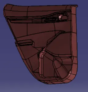
Class A Surface
PROCEDURE:
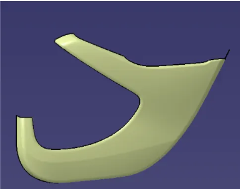
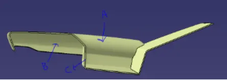
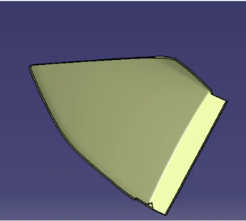
From the given class A surface we have to separate the map pocket, armrest, lower substrate.
Given Class A Surface
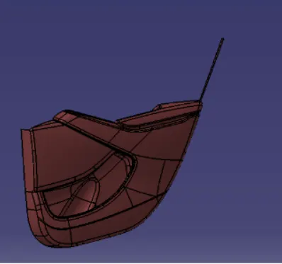
After separating them individual joints are formed.
Map Pocket -
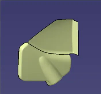
Arm Rest -
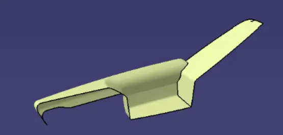
Lower Substrate-
Creation of Class B surface:
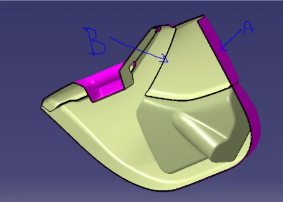
Class B surface is the second surface that is inside the Class A surface. It can be created by just making an offset for the class A surface. The min offset is given
as 2mm inside direction to the class A surface. After making an offset there will be some patches that are to be worked out and cleared so that class B is created
without errors.
Class A and Class B Surface
Creation of class C surface:
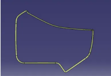
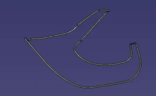
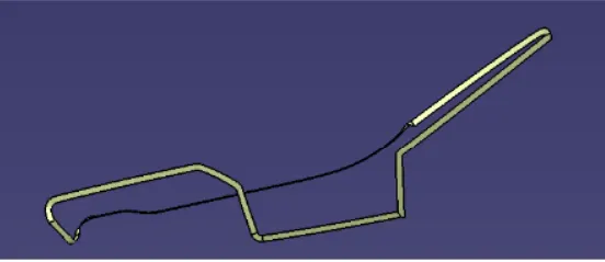
Class C is the joining of the class A and class b surface. It is created using a sweeping command with reference to the surface.
For example, take a map pocket. Extract the boundary of the map pocket and make a sweep using the reference surface of the map pocket to get the C surface.
C Surface for Map pocket
- Similarly the C surface is done for the armrest and lower substrate in the same way
* C Surface for lower substrate
*C Surface for Arm Rest
-To get the final design to join the C surface with the B surface and make trim with the A surface.
Arm Rest
Map pocket
Lower substrate
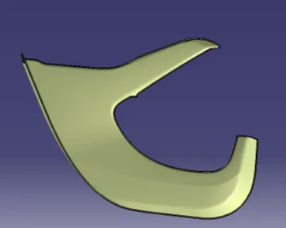
Lower map pocket
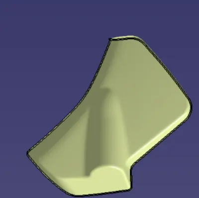
FINAL BODY:
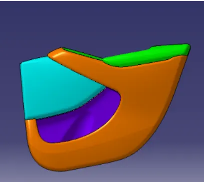
Creation of tooling Axis:
*What is the tooling axis?
-This is the tooling direction in which the surface is cleared. Some small patches will not be cleared in some cases.
To avoid that the side core axis is provided to clear in that direction.
The tooling axis is the perpendicular line created on the surface.
-Tooling axis with reference to map pocket
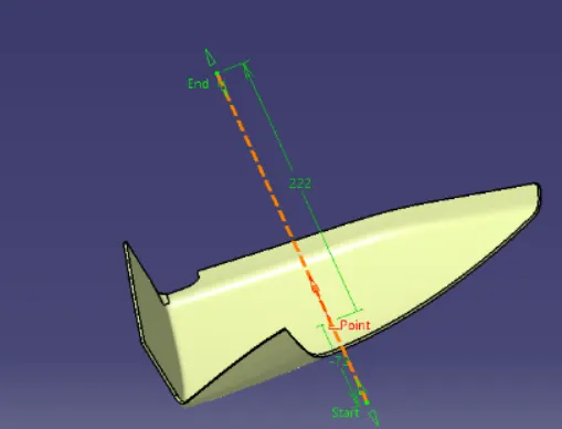
-Since the other parts of the door panel are perpendicular to the tooling axis this tooling axis can be taken as the main tooling axis for all the other parts.
Draft Analysis:
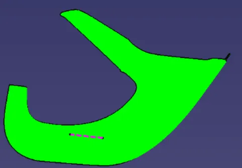
-Draft Analysis for Class A surface :
The draft is required to eject the parts from the mould properly. The draft is the angle at which the tapered is allowed to release. The minimum draft angle is ½
or 1 degree but 3 degrees is widely accepted. Draft Analysis is done by dragging the compass onto the tooling axis and lock the compass. Select the surface to
get the draft analysis.
-In this Armrest, draft analysis is not cleared using the tooling axis so the side core axis is created to clear the remaining part of the surface.
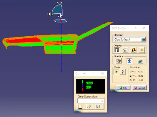
- Similarly, draft analysis is done on the other A surfaces.
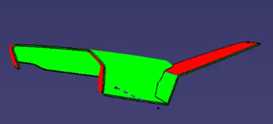
-Draft analysis for Map pocket
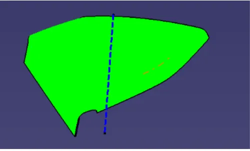
-Draft analysis for lower map pocket
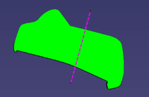
-Draft analysis for lower substrate
-Draft Analysis for final body:
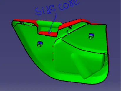
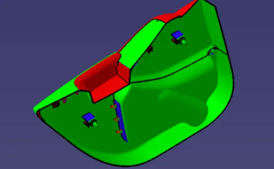
The same procedure is followed similar to the class A surface
B Side Features:
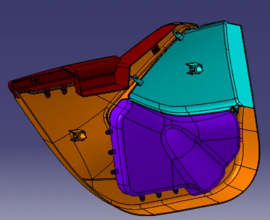
The B side features are created based on the master section given. By following the master section and design rules the B side features are designed. Flanges,
heat stakes, screw boss, dog house with push clip are designed in our design.
Dog house:
The main function of the Dog house is to avoid sink marks.
The rules to be followed to create a dog house are:
1. Minimum height of 6mm or less.
2. Width ratio
3:1 3. Minimum draft of 1.5deg.
4. C value should be 40% of the nominal thickness i.e 3 to 6mm
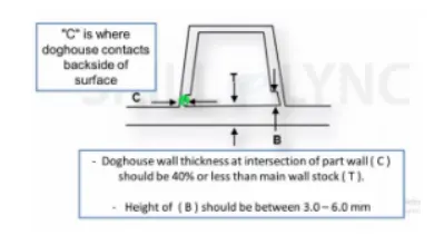
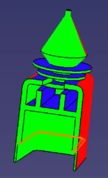
Following the above design rules, the dog house is created and a draft analysis is done in which the ribs and inside will be cleared with the help of the side core
axis or lifter axis.
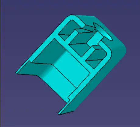
-The above-shown marks are not cleared using the tooling axis so the side core axis is created to clear them.
-The push clip is designed by following the below rules.
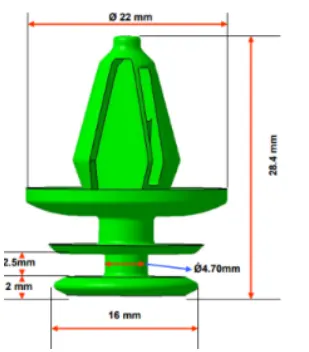
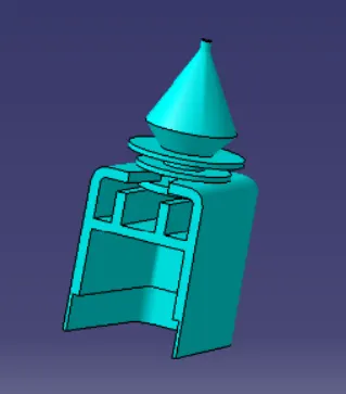
-Dog house with push clip.
-Draft analysis
Screw Boss:
General design rules for screw boss are;
1. Draft of 5deg on each wall.
2. Wall thickness of 40% of nominal thickness.
3. Min fillet 0.25mm.
4. Height ratio 3:1 but 2:1 is preferred.
5. Ribs should follow the rib design rules.
Ribs:
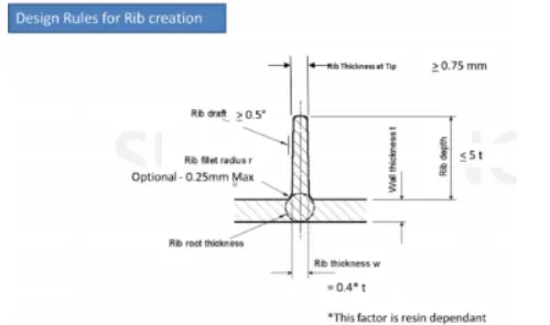
General design rules for ribs are:
1. Min draft per side is 0.5deg.
2. The thickness of ribs should be 40% of nominal thickness.
3. Height <=5 times the wall thickness.
4. Min thickness at the tip is 0.75mm
5. Fillet is 0.25m 6. Rib root thickness should be 30% of the wall thickness.
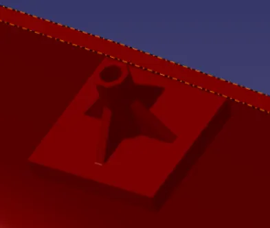
Screw bose
-Flanges and heat stakes:
-These are created based on the master section given but only one master section is given so with reference to that remaining flanges are designed. For heat
stakes also same with reference to one master section. clearance between the flange and heat stake is 1mm.
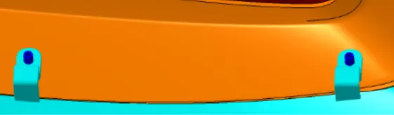
-One flange and heat stake are created and then they are translated using point-to-point translation.
The images of the complete model: