Week 11 - Final project
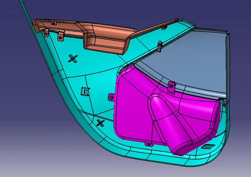
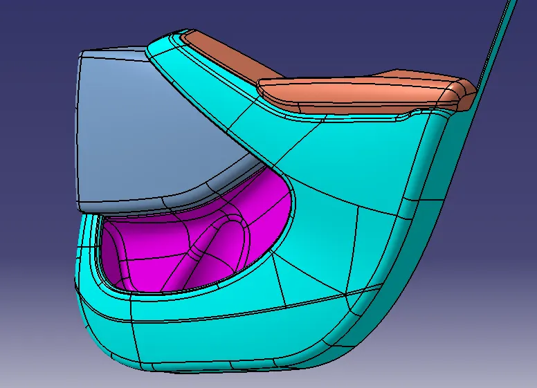
AIM : To create and design the Plastic Door Trim Panel from given Class-A surface along with Master-Section by considering inputs as like in OEM and tier1 companies
OBJECTIVES
- Create the sketch by using Positional Sketch
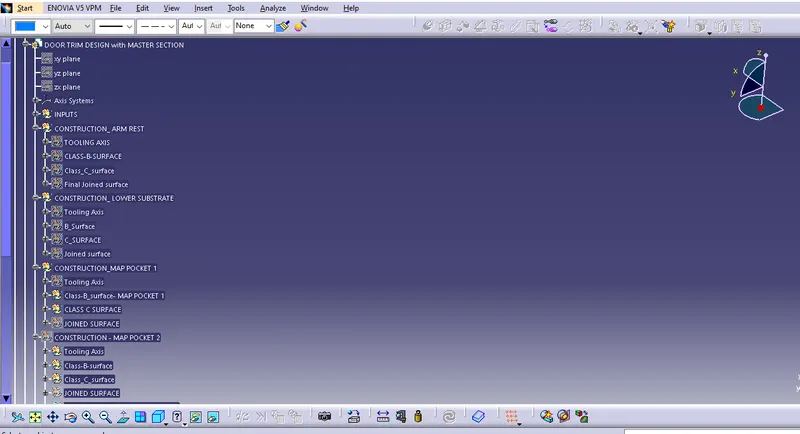
- Ensure proper Tree Structure
- Geometrical sets should have a proper nomenclature
- Create thickened part by using Master-section
- Create the different mountings as per design guidelines
- Create Draft Analysis and Tooling Axis
- Creation of Parting-Line
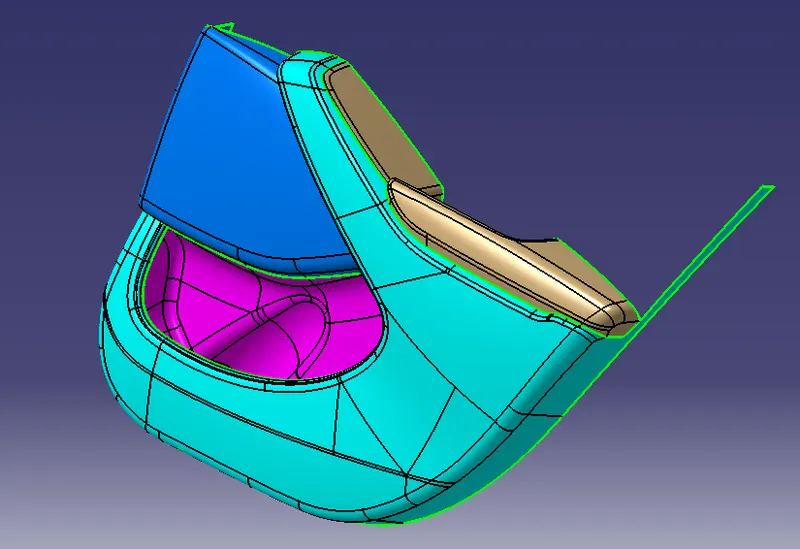
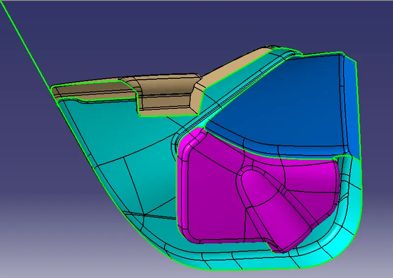
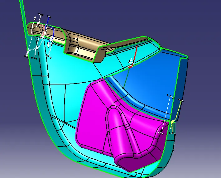
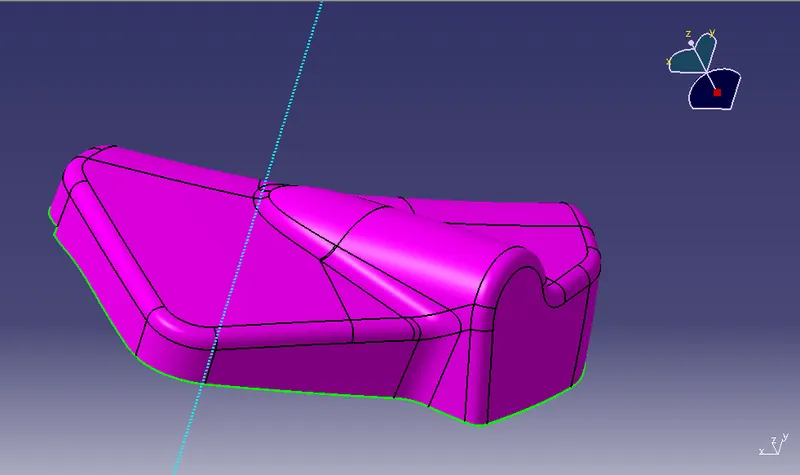
Given Class-A surface of Door Trim
PROCEDURE
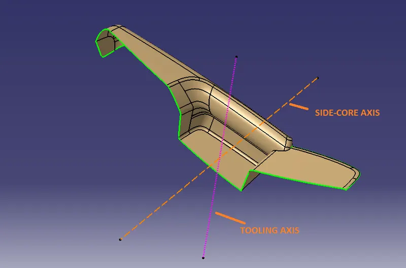
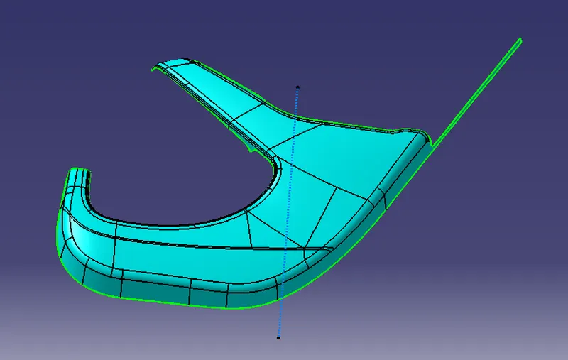
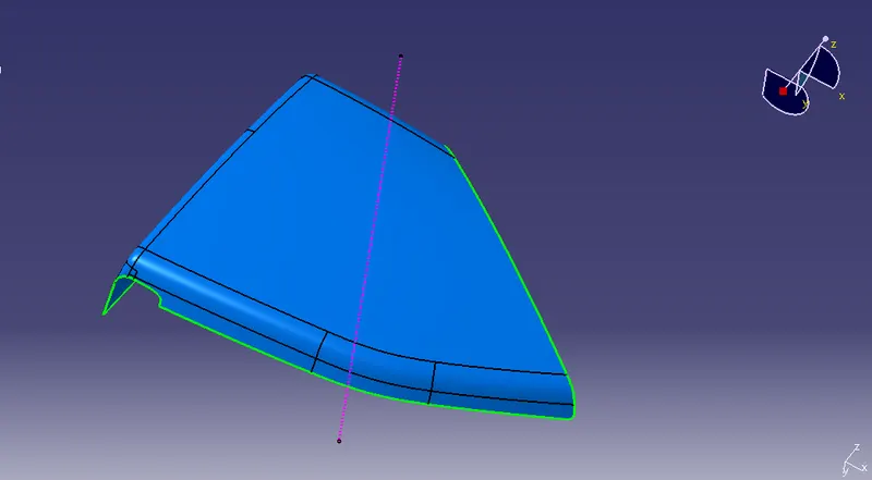
TOOLING AXIS
ARM REST
- Extract the surface and create a point.
- create proper Tooling axis at that point and also create a Side-core Axis.
LOWER SUBSTRATE
MAP POCKET-1
MAP POCKET-2
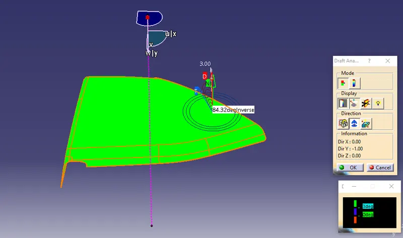
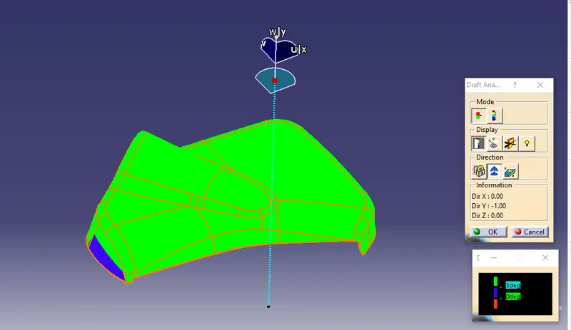
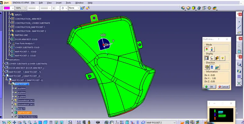
DRAFT ANALYSIS
- Allign the COMPASS in proper way along with Tooling axis and Side-core Axis.
- change Material mode to Customise View Parameter
- The applied Draft angle = 3degree
DOOR ARM REST : CLASS_A SURFACE

(with main Tooling Axis)
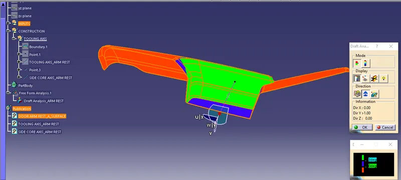
(with Side-Core Axis)
LOWER SUBSTRATE
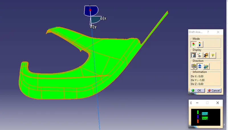
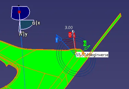 (Draft angle = 3degree)
MAP POCKET-1
MAP POCKET-2
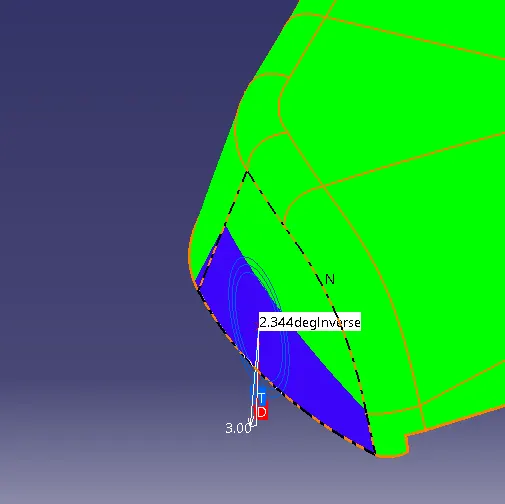
(The blue patches will clear in other side core axis, having minimum draft = 2.3 degree)
CLASS-B SURFACE
In Class-A surface, there is so many stylling curves, surfaces present and these curved fillets are difficult to simplify. So, we offset the A-surface to get B-Surface.
- OFFSET = 3 mm, To get the Class-B surface for getting the thickness.
- Modify the surface, by using Extract, Boundary, Extrapolate, Join, Split, Trim, Multi-sections surface
DOOR ARM REST
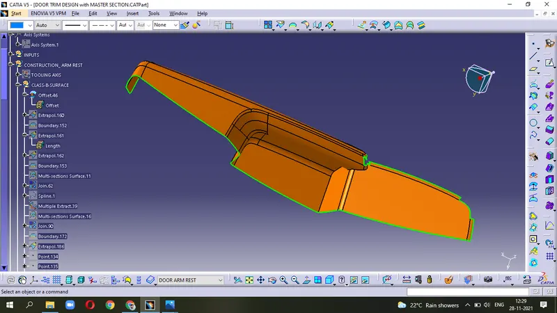
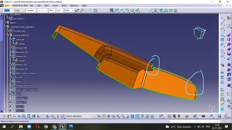
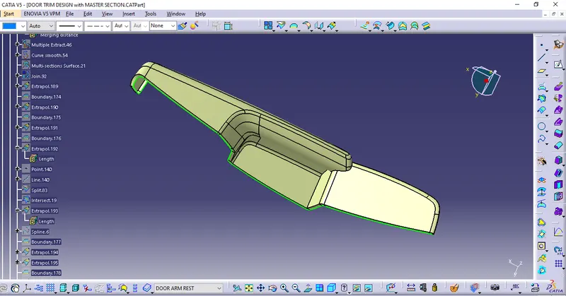
(ARM REST : B_Surface )
LOWER SUBSTRATE
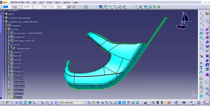
(LOWER SUBSTRATE : B_SURFACE)
MAP POCKET-1
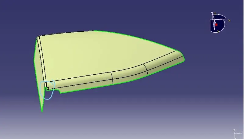
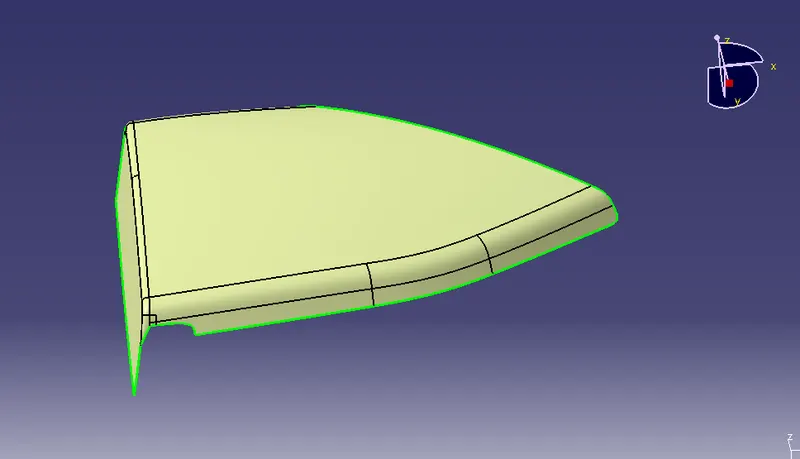
(MAP POCKET-1 : B_SURFACE)
MAP POCKET-2
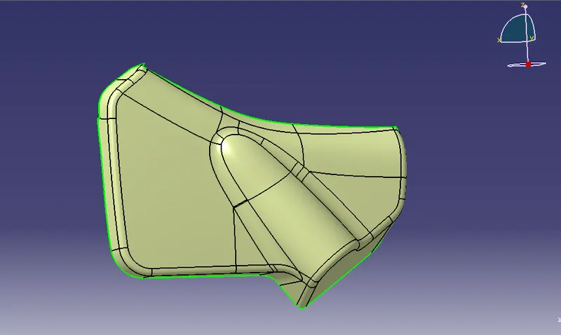
(MAP POCKET-2 : B_SURFACE)
CLASS-C SURFACE
- Create the Boundary
- Use the Boundary to Sweep - with reference surface for all.
- JOIN the Sweeped surfaces
DOOR ARM REST
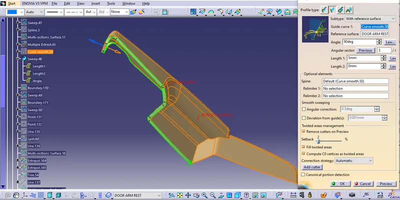
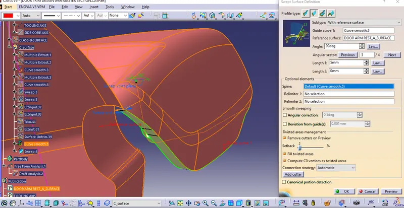
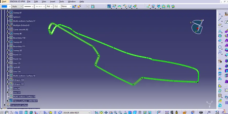
(DOOR ARM REST : CLASS-C SURFACE)
LOWER SUBSTRATE
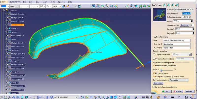
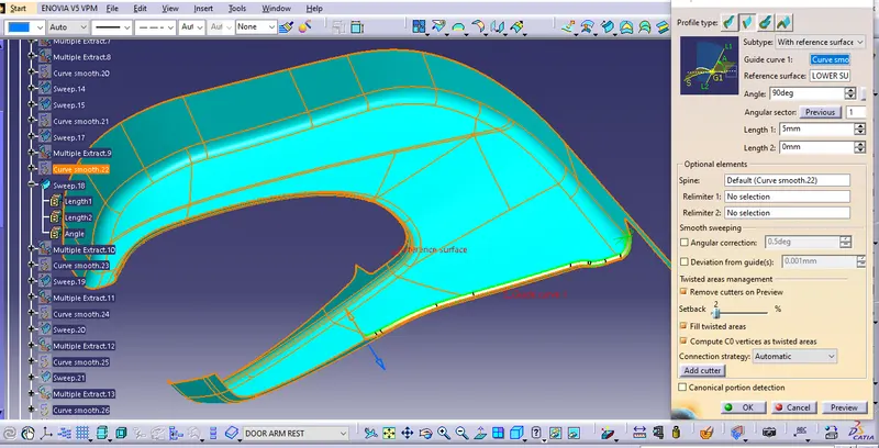
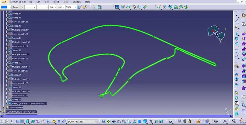
(LOWER SUBSTRATE : Class_C surface)
MAP POCKET-1
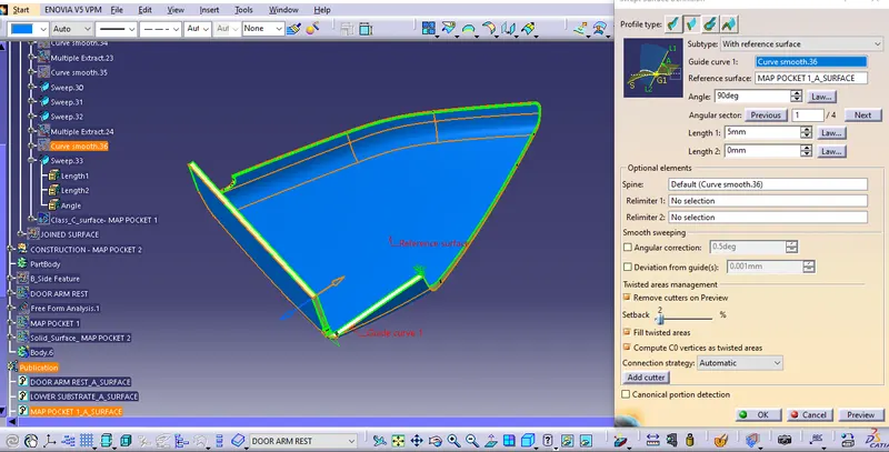
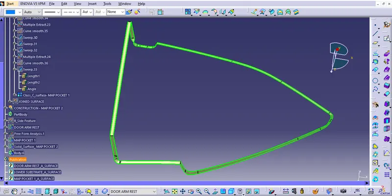
(MAP POCKET-1 : Class_C surface )
MAP POCKET-2
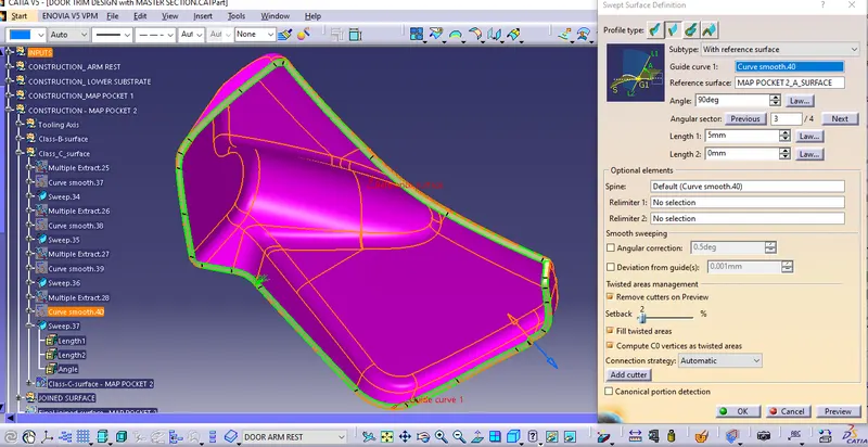
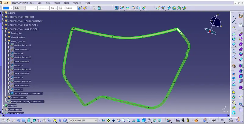
(MAP POCKET-2 : Class_C surface)
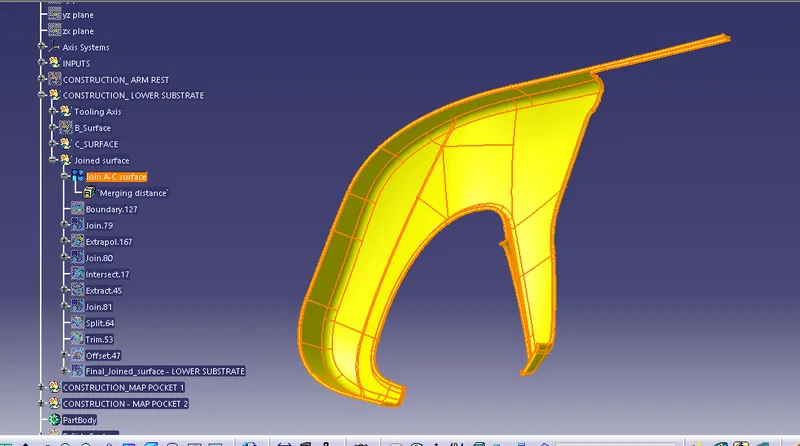
FINAL : JOIN SURFACE
- JOIN Class-A surface and Class-C surface.
- TRIM this Joined surface with Class-B surface.
- we get the Final closed surface.
(NOTE : Try to create a Boundary on this surface; if Error occurs then our surface is ready for the creation of Solid Body)
- Goto Part Design and use CLOSE SURFACE to make the solid body.
DOOR ARM REST
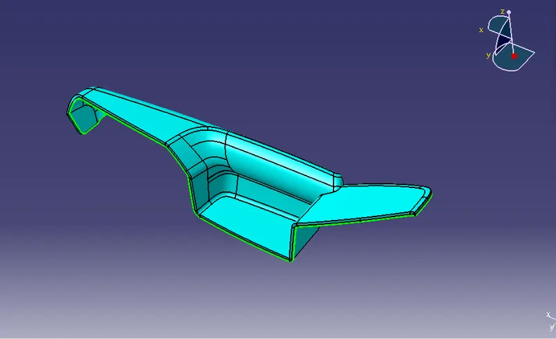
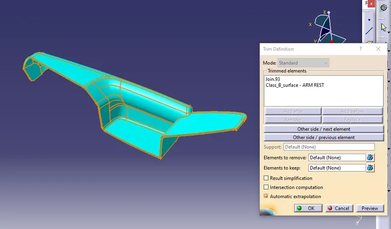
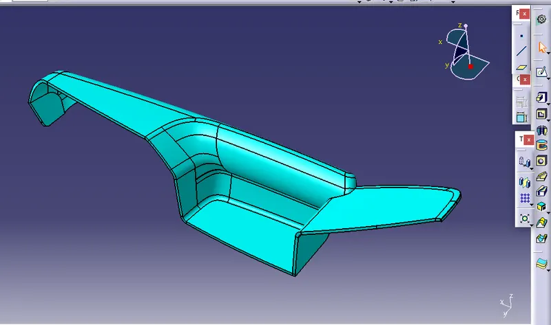
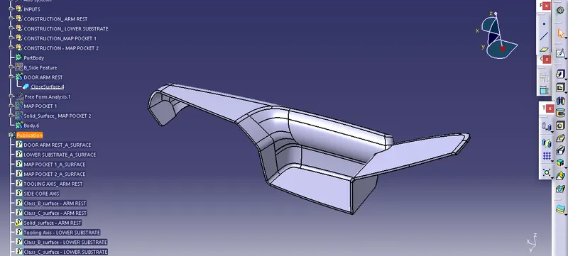
(DOOR ARM REST : SOLID Body)
LOWER SUBSTRATE
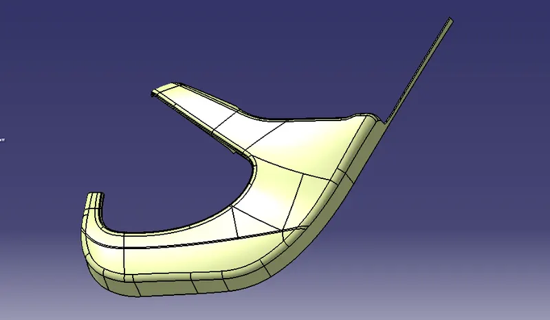
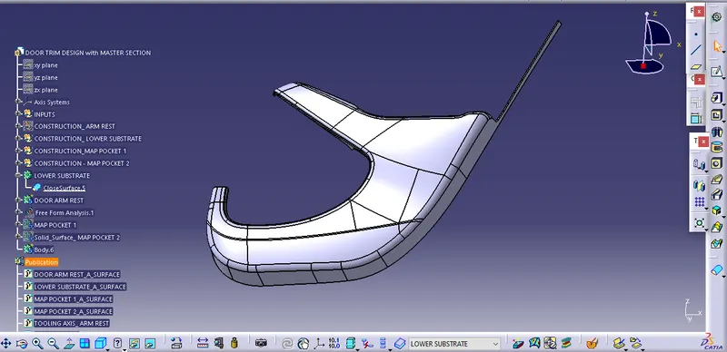
(LOWER SUBSTRATE : Solid Body)
MAP POCKET-1
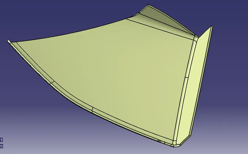
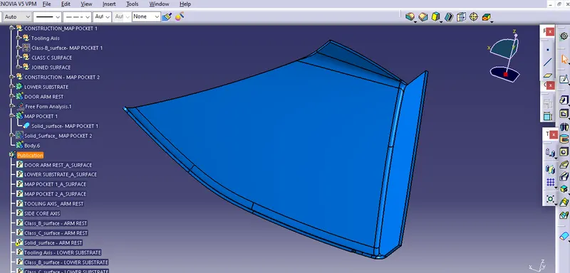
(MAP POCKET-1 : Solid Body)
MAP POCKET-2
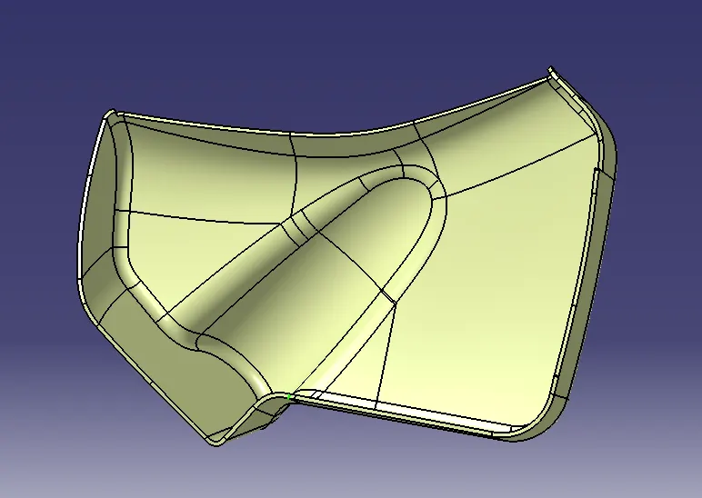
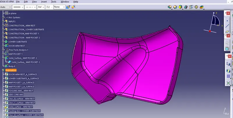
(MAP POCKET-2 : Solid Body)
DRAFT ANALYSIS : FINAL SOLID BODY
- Convert Material mode to Customise View Parameter
- Unhide Tooling Axis
- Allign the Compass properly in the Tooling Axis.
- Draft angle = 3degree
DOOR ARM REST
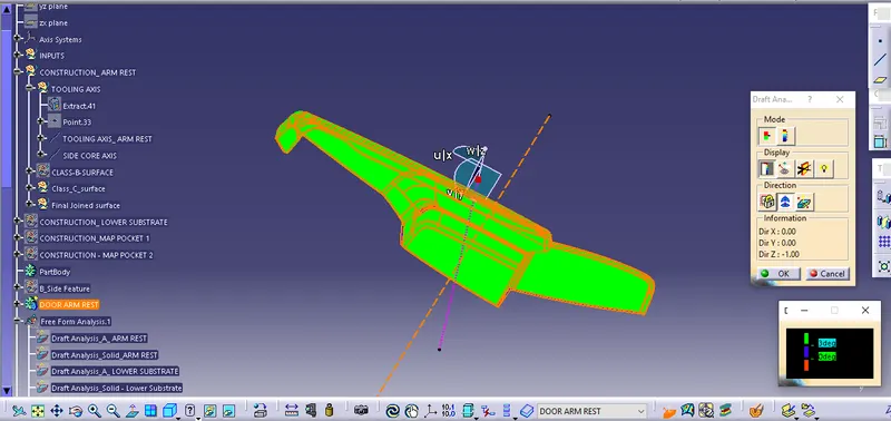
(with Main Tooling Axis)
All green surfaces have draft angle = 3degree
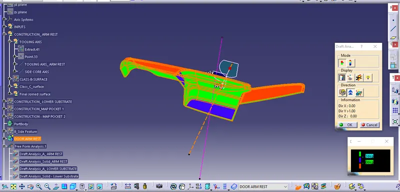
(with Side-Core Axis)
LOWER SUBSTRATE
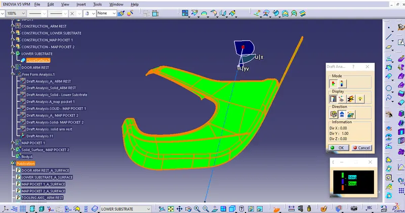
All green surfaces have draft angle = 3degree
MAP POCKET-1
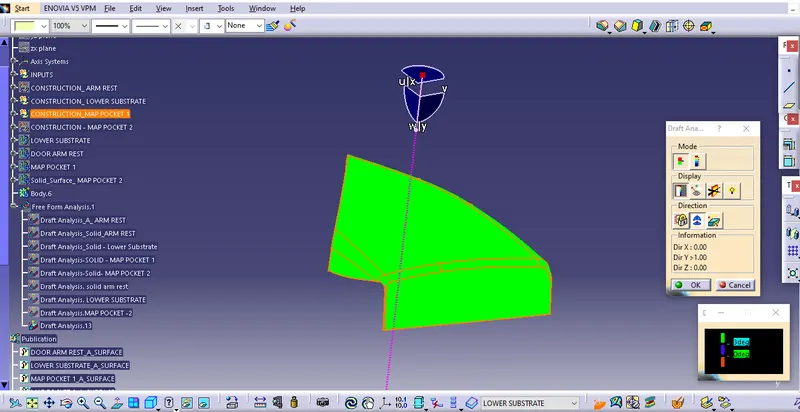
All green surfaces have draft angle = 3degree
MAP POCKET-2
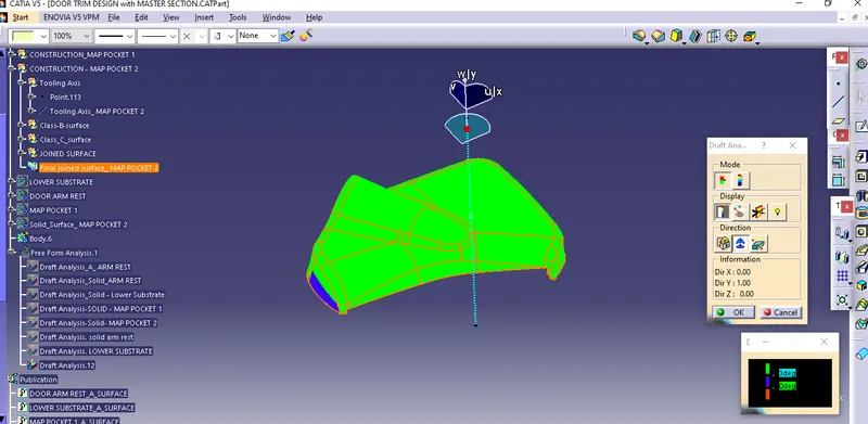
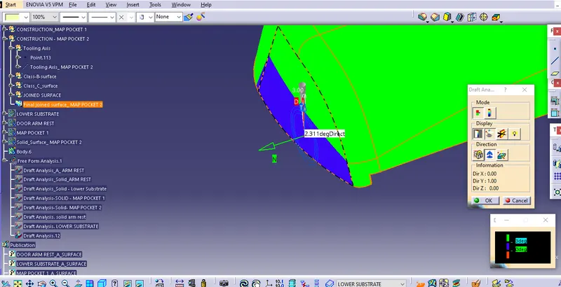
All green surfaces have draft angle = 3degree
(Blue patch have minimum draft angle = 2.3degree, ang will clear with side core axis)
Parting Line
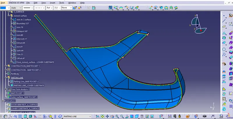
It is the area in which Parting surface and the component meets. In other words, It is the exact juction between the Core half and Cavity half.
- It should have Class-A and Class-C surface.
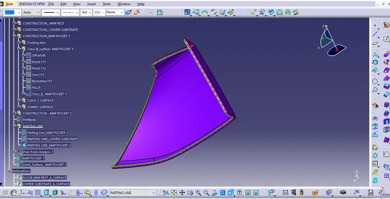
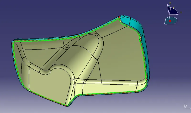
- Intersect the JOIN surface (Class_A + Class_C) with the Class_B surface.
- Doted line is the Parting Line.
LOWER SUBSTRATE
MAP POCKET-1
MAP POCKET-2
B-Surface Feature
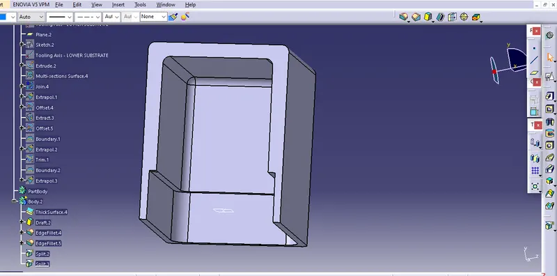
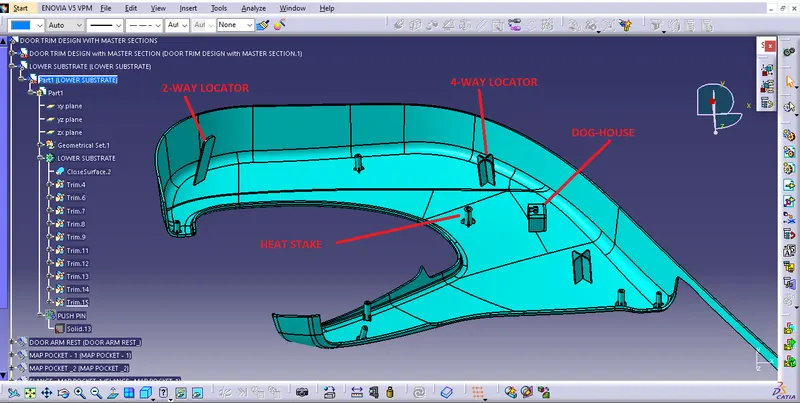
Dog-House:-
Dog-House is the Engineering supporting feature used in Plastic Designing.
- It helps to avoid sink marks.
- It also provide enough strength to joinn different surface having large distance between them.
Designing Rule of Dog-House
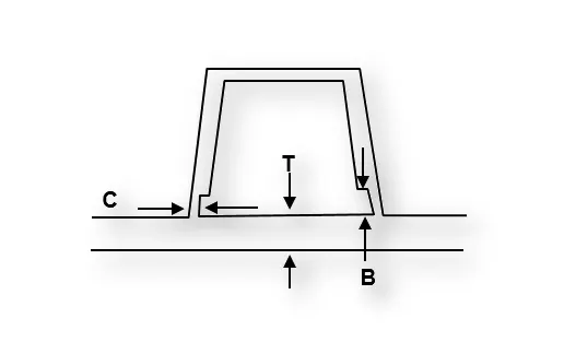
- Dog-House wall thickness = 0.4*T (T=thickness of component)
- Height(B) = 3 to 6 mm
- steel Width/Height ratio = 3:1
- 'C' is where Dog-House contacts the backside of the surface.
PROCEDURE
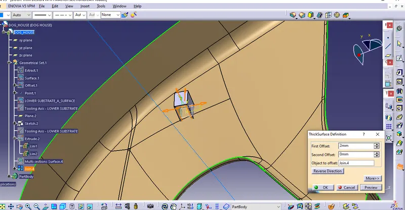
- EXTRACT the surface and EXTRUDE it
- make Thickness = 2mm
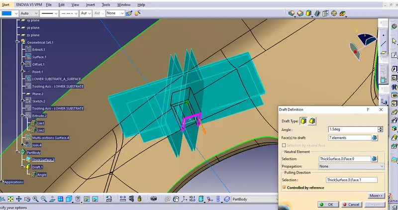
- Draft angle = 1.5 degree
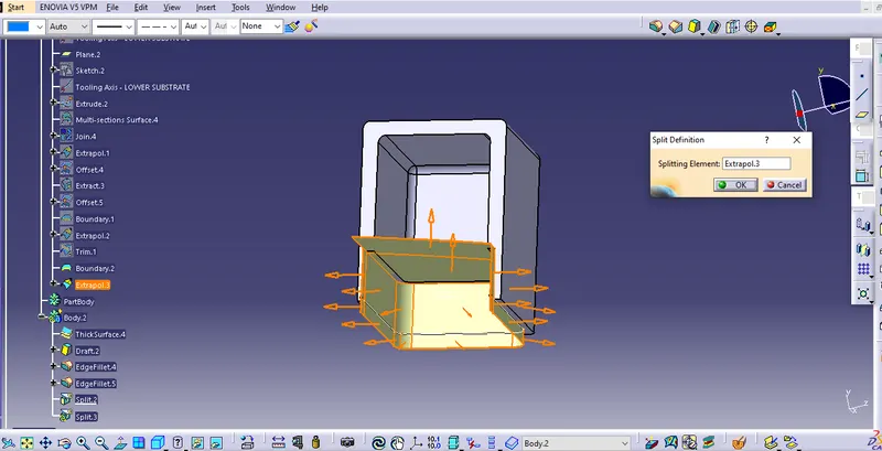
- offset the EXTRACT surface and apply the SPLIT operation to get proper Dog-House.
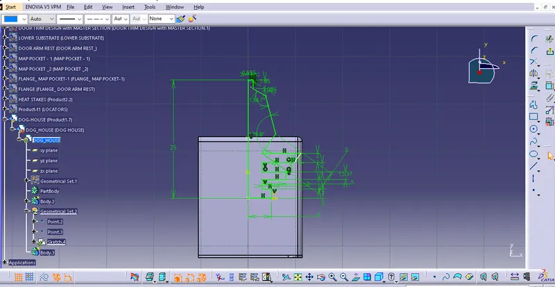
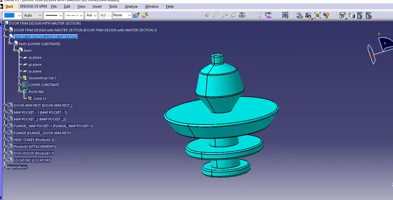
PUSH - PIN Creation
- make a Positional sketch
- apply SHAFT operation along appropriate plane
- apple fillets at the Edges.
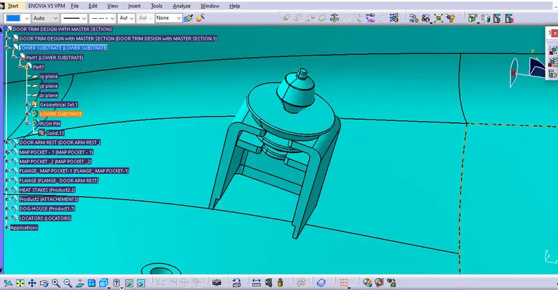
- TRANSLATE the PUSH-PIN on the Dog-House.
HEAT STAKING :-
- It is the process to join thermoplastic to a part of dissimilar material weather it be Metal, dissimilar plastic or other material.
- also known as Plastic Welding.
Advantage -
- similar or dissimilar material can be join. like- metal to metal, plastic-metal, plastic-plastic
- multiple fastening points.
- Reduced cost of machinery
DRAFT Angle = 0.5 degree
(It should be below the Locators)
LOCATORS:-
In the process of fixing of two component/part, we need to fix the part and mating point in such a way that It will be in proper allignment and will not move in other direction.
For that, we use Locators : 2-way Locators, 4-way Locators
3-2-1 Principle - Any part which is going to fix; having 12 degrees of freedom.
- Translational Movement - along X,Y,Z axis
- Rotational Movement - along X,Y,Z axis
DESIGN RULE : 4-WAY LOCATORS and 2-WAY LOCATORS
- Draft angle = 0.5degree
- chamfer=3mm on corner
- Fillet edge Corner=3mm
- Fillet side faces = 0.25mm to 0.3mm
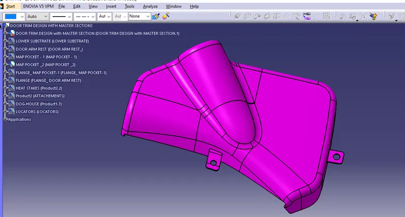
FLANGES
It is used for the attachements of Heat-Stake and Locators.
DRAFT ANALYSIS
LOWER SUBSTRATE
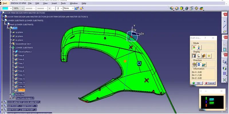
All green faces have draft angle = 3 degree
ARM REST
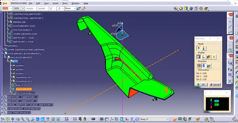
(with main Tooling axis)
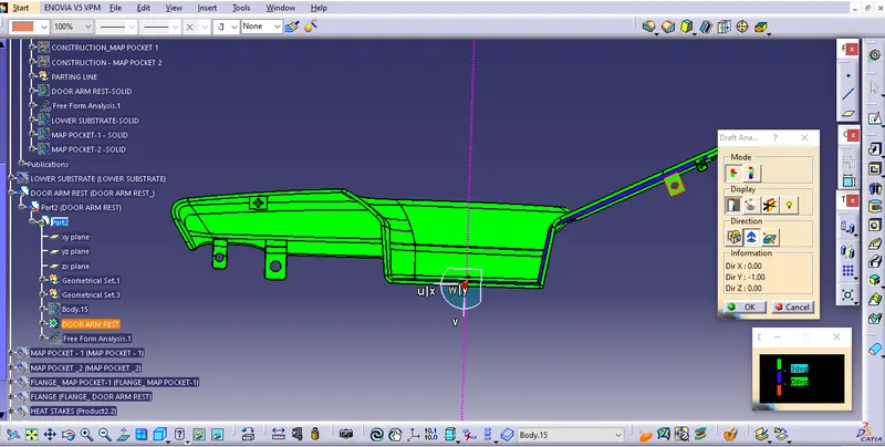
(with side-core axis)
MAP POCKET-1
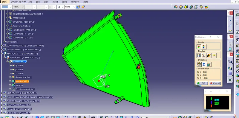
All green faces have draft angle = 3 degree
MAP POCKET -2
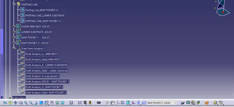
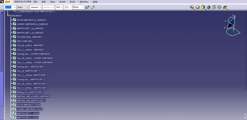
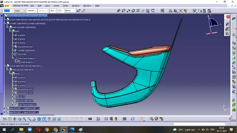
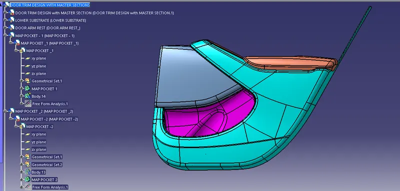
GEOMETRICAL SETS
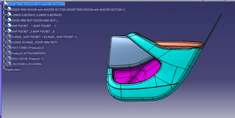
DIFFERENT VIEW
LOWER SUBSTRATE
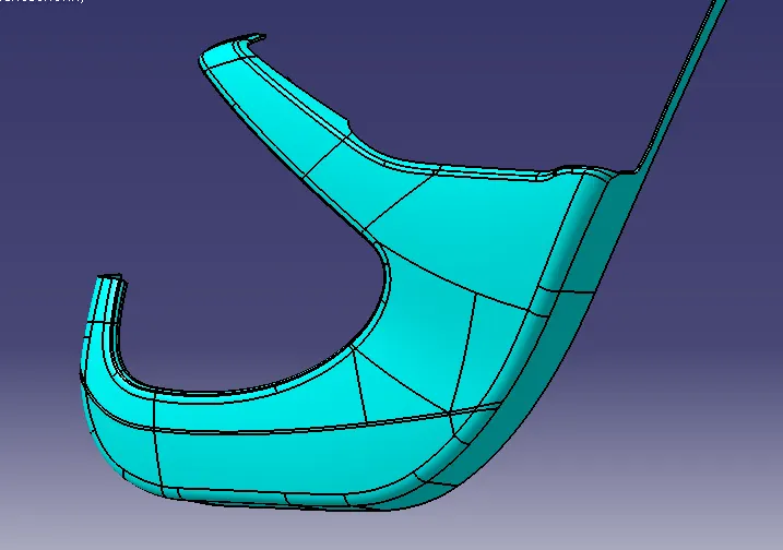
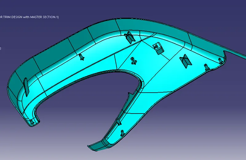
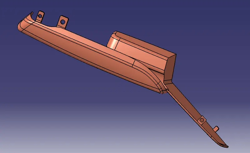
DOOR ARM REST
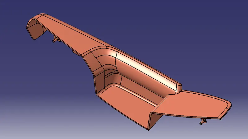
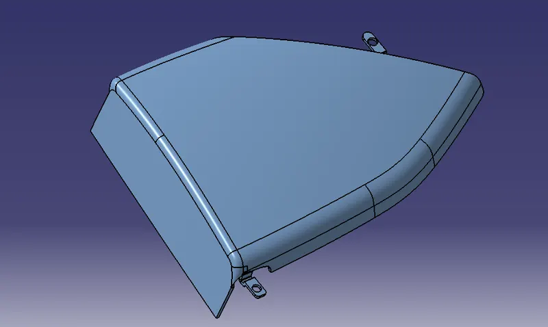
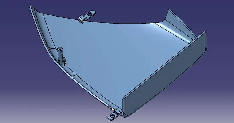
MAP POCKET-1
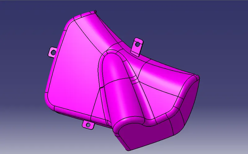
MAP POCKET-2
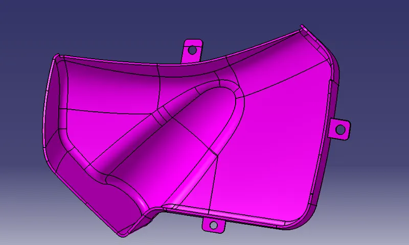
FINAL DOOR TRIM PANEL