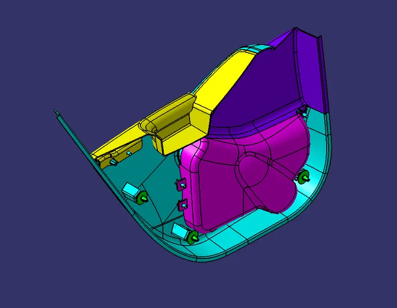
Door Trim Panel Assembly Design
DOOR TRIM PANEL ASSEMBLY WITH ENGINEERING FEATURES
DESIGN METHODOLOGY:
In order to design the door panel assembly, we have been given input as class A surfaces of individual components and corresponding master sections for engineering features and flange development.
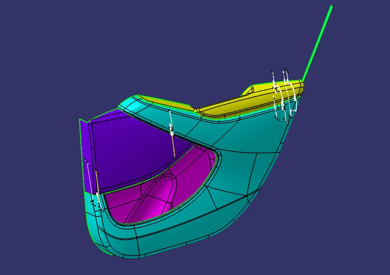
With the help of these we develop each component as a separate part in the assembly workbench itself. The components are as follows,
- Arm Rest
- Map Pocket 1
- Map Pocket 2
- Lower Substrate
Depending on required engineering features we will add number of push clips required to the assembly as separate parts.
PROCEDURE:
We start by adding the input as the first part in the assembly. Then we add other parts to the assembly using ‘New Part’ command in assembly workbench. Now we develop each part solid body and features through procedure described ahead.
Arm rest:
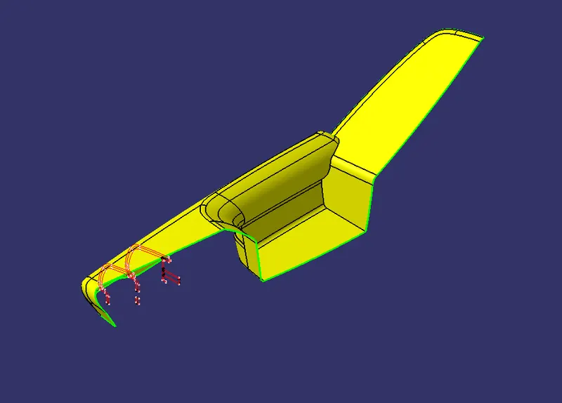
- First, we take the given input class A surface into the part, and then check for surface quality.
- Correct any errors or irregularity found in the Class A surface (in this case there was an open edge).
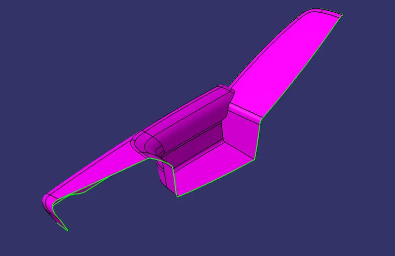
- Then on the improved class A, develop the tooling axis.
- In this case we need a side core too as the part has certain undercuts.
- For the main tooling axis, when we look at the body from different views, we can see the Z axis should be appropriate for main tooling axis. Then extract a surface as shown, take a point on the surface and take a line through this point and along Z axis.
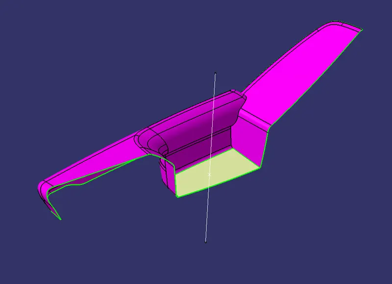
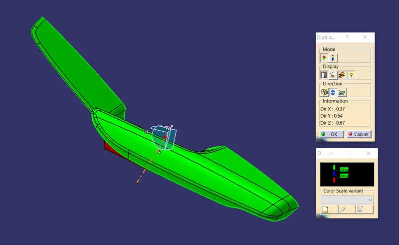
- Now in draft analysis we check for result and as the result is not positive, we adjust the compass direction to get desired result. Then we use the compass direction to take another line which will be our main tooling axis.
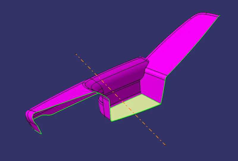
- Then for side core tooling axis we take another line and use compass for adjusting it in draft analysis. Thus, we can get the side core tooling axis from the compass direction.
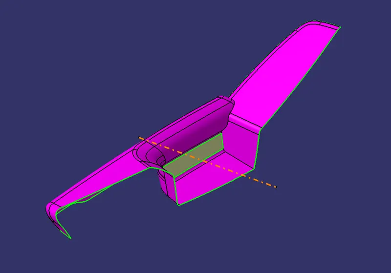
- After that we develop the class B and class C surfaces for the part.
- Once we get class B and C surfaces, we get a closed surface body by trimming them together.
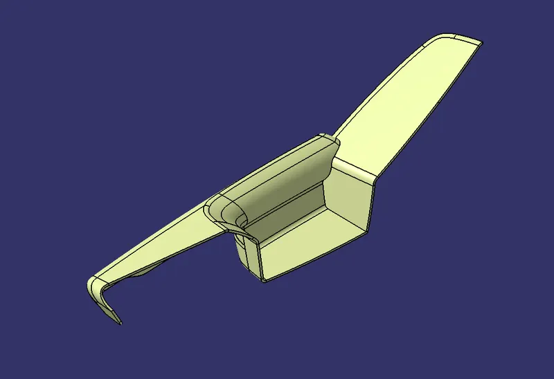
- Then we can form the solid body using ‘Close Surface’ command in part design.
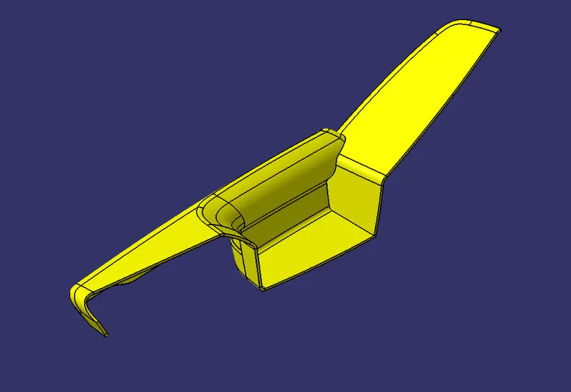
- After that we can develop the flanges on the part by using the master sections and following the close surface body method above.
- We can add the flange solid body to the main body using Boolean operations.
- Further, required modification on the part can be done after developing engineering features and attachment strategy. They are mentioned in later part of the report.
Map Pocket 1:
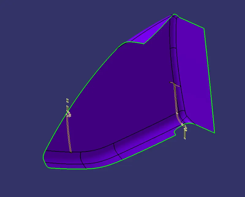
- First, we take the given input class A surface into the part, and then check for surface quality.
- Everything seems fine in this case, so move to the tooling axis.
- For the tooling axis, when we look at the body from different views, we can see the Y axis should be appropriate for tooling axis. Then extract a surface as shown, take a point on the surface and take a line through this point and along Y axis.
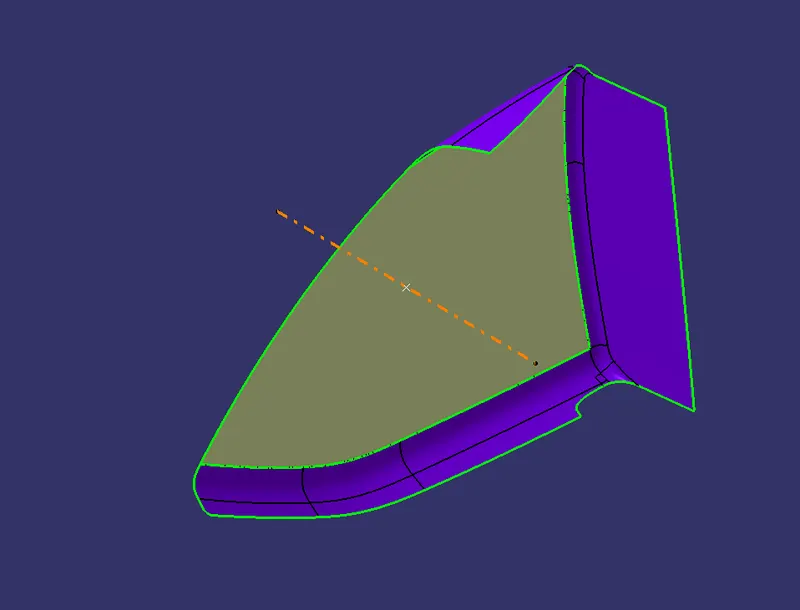
- Now in draft analysis we check for result and as the result is positive, we can take this line as our final tooling axis.
- There is no need for side core tooling axis as the part is cleared in main tooling itself and result is fine in draft analysis.
- After that we develop the class B and class C surfaces for the part.
- Once we get class B and C surfaces, we get a closed surface body by trimming them together.
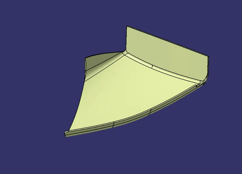
- Then we can form the solid body using ‘Close Surface’ command in part design.
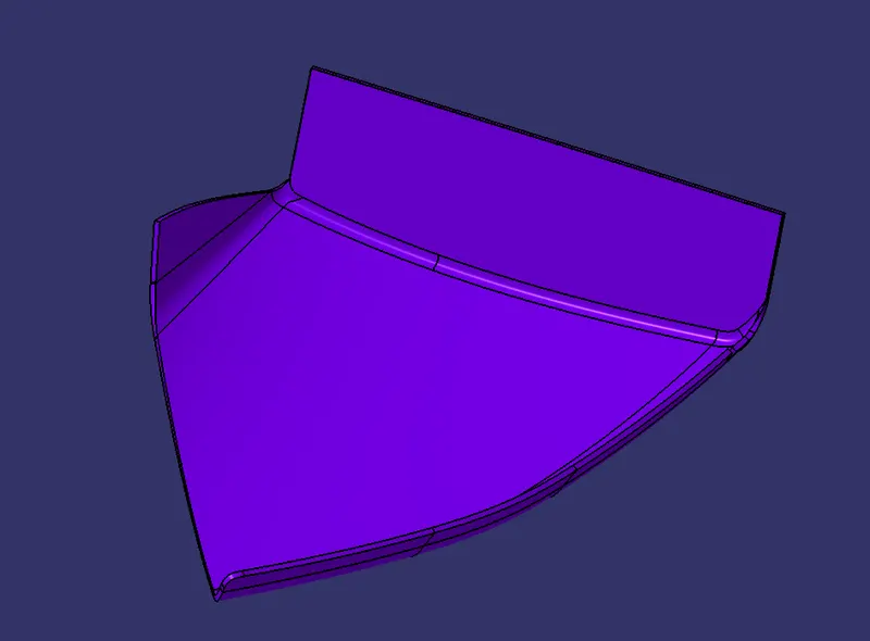
- After that we can develop the flanges on the part by using the master sections and following the close surface body method above.
- We can add the flange solid body to the main body using Boolean operations.
- Further, required modification on the part can be done after developing engineering features and attachment strategy. They are mentioned in later part of the report.
Map Pocket 2:
- First, we take the given input class A surface into the part, and then check for surface quality.
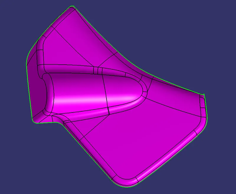
- Everything seems fine in this case too, so move to the tooling axis.
- For the tooling axis, when we look at the body from different views, we can see the Y axis should be appropriate for tooling axis. Then extract a surface as shown, take a point on the surface and take a line through this point and along Y axis.
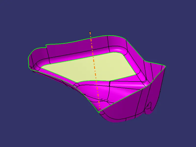
- Now in draft analysis we check for result and as the result is positive, we can take this line as our final tooling axis.
- There is no need for side core tooling axis as the part is cleared in main tooling itself and result is fine in draft analysis.
- After that we develop the class B and class C surfaces for the part.
- Once we get class B and C surfaces, we get a closed surface body by trimming them together.
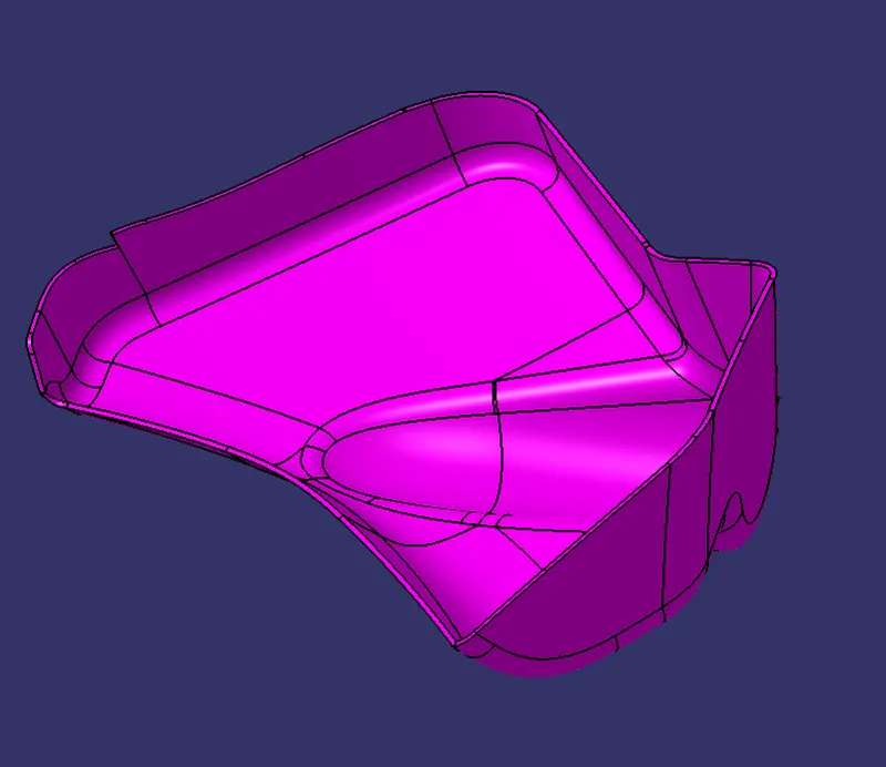
- Then we can form the solid body using ‘Close Surface’ command in part design.
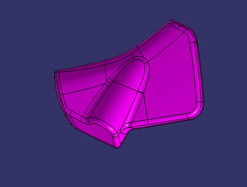
- After that we can develop the flanges on the part by using the master sections and following the close surface body method above.
- We can add the flange solid body to the main body using Boolean operations.
- Further, required modification on the part can be done after developing engineering features and attachment strategy. They are mentioned in later part of the report.
Lower Substrate:
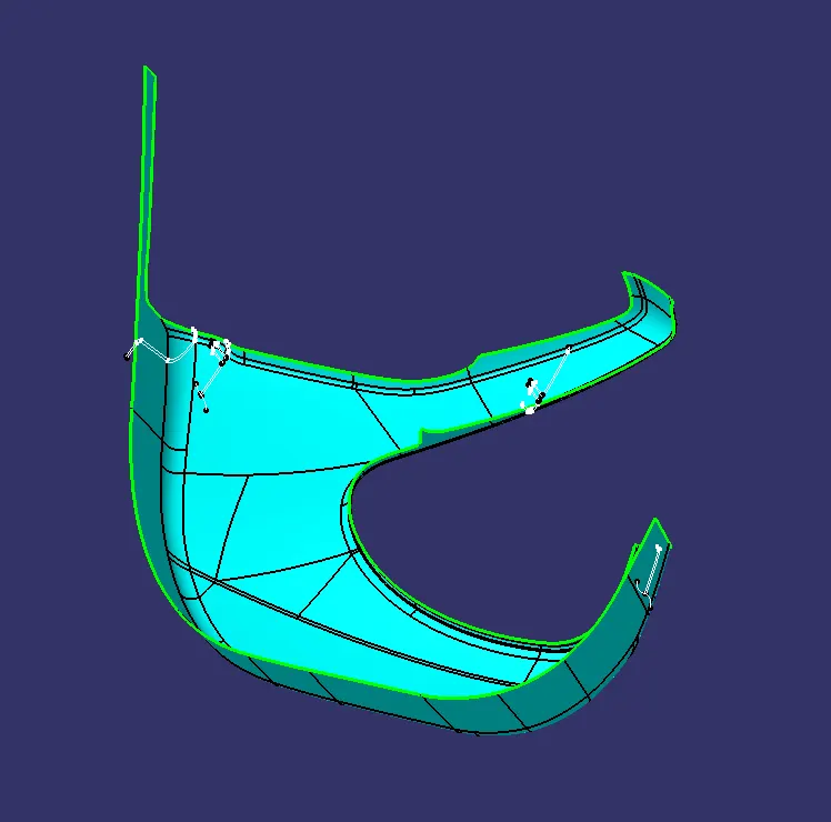
- First, we take the given input class A surface into the part, and then check for surface quality.
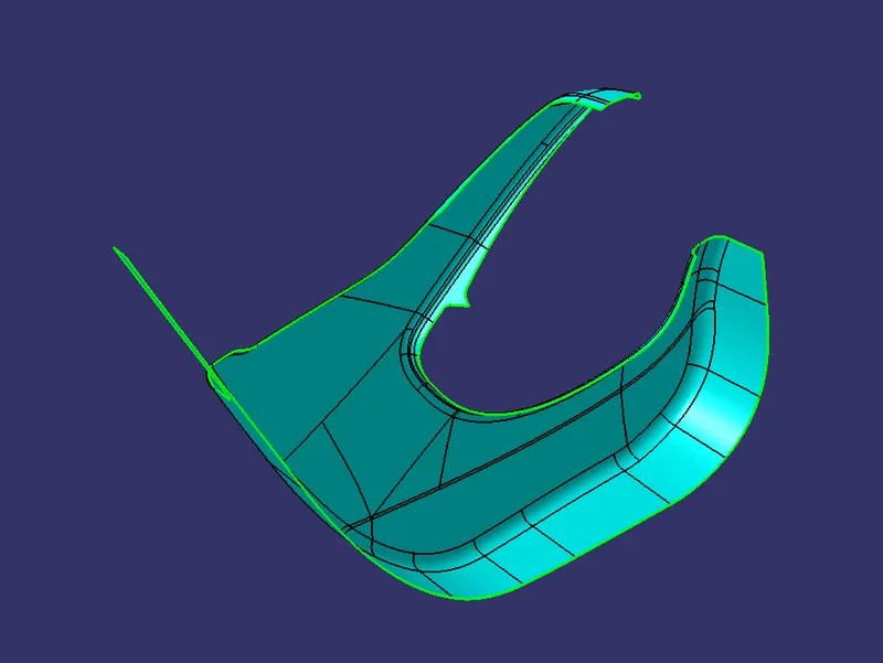
- Everything seems fine in this case too, so move to the tooling axis.
- For the tooling axis, when we look at the body from different views, we can see the Y axis should be appropriate for tooling axis. Then extract a surface as shown, take a point on the surface and take a line through this point and along Y axis.
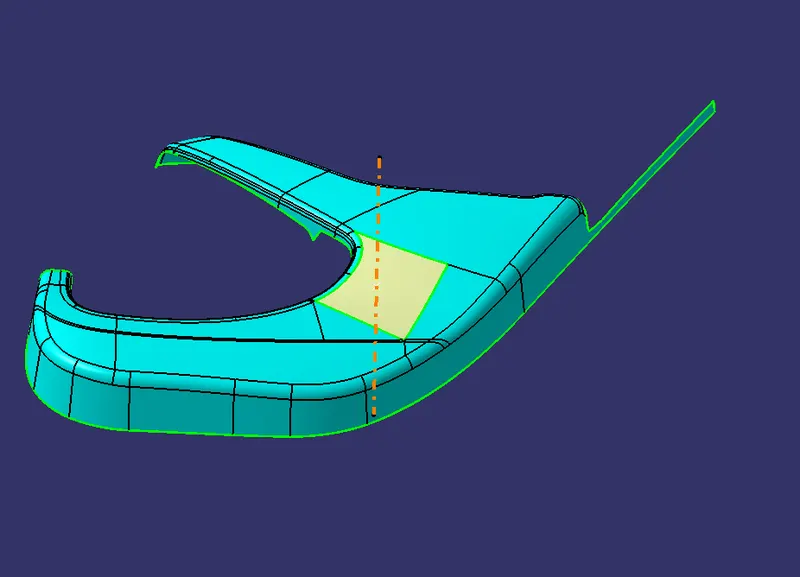
- Now in draft analysis we check for result and as the result is positive, we can take this line as our final tooling axis.
- There is no need for side core tooling axis as the part is cleared in main tooling itself and result is fine in draft analysis.
- After that we develop the class B and class C surfaces for the part.
- Once we get class B and C surfaces, we get a closed surface body by trimming them together.
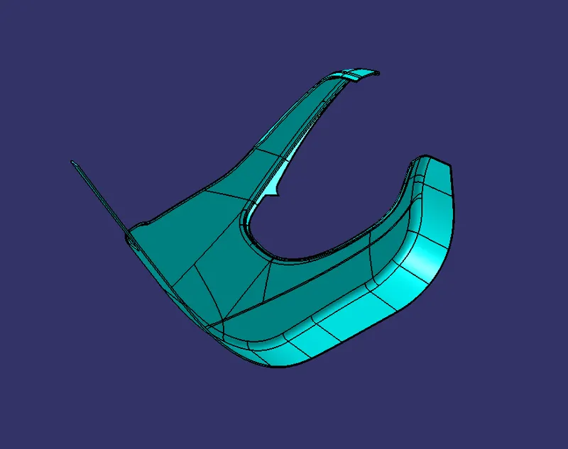
- Then we can form the solid body using ‘Close Surface’ command in part design.
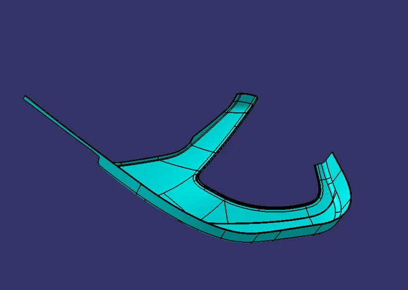
- After that we can develop the flanges on the part by using the master sections and following the close surface body method above.
- We can add the flange solid body to the main body using Boolean operations.
Engineering Features Development:
- Now, as other components are to be attached to this lower substrate, we can move to developing engineering features and attachment strategy.
- We will use heat stakes to attach the component and provide push pin clips on doghouses to attach the lower substrate to door panel further.
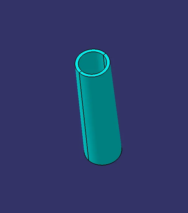
- So, we create heat stakes at appropriate positions considering the relative positions of other parts.
- It is important to note that the heat stakes must have support ribs for strengthening purpose.
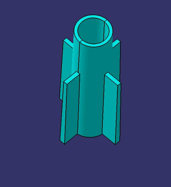
- It must also be remembered that the rib vertical surfaces must have a draft of at least 0.5 degrees along the tooling axis.
- We can create one heat stake and translate the same to various positions using ‘Translate’ command in Part design.
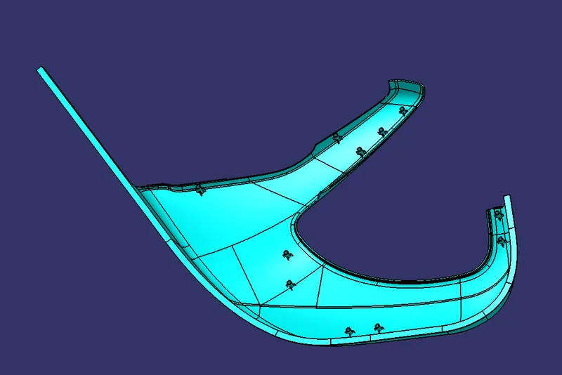
- Then we need to create locators along with heat stakes for the purpose of locating in the heat staking process.
- For that we will have 1 four-way locator and 1 two-way locator for Arm Rest, 1 four-way locator for Map Pocket 1 and again 2 four-way locaters for Lower Substrate.
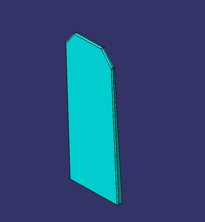
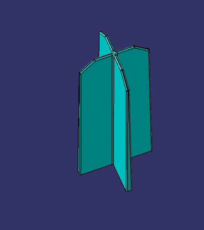
- It is important to note here that the height of all locators from the component surface should be more than that of the heat stakes as locating will happen before the actual heat staking process.
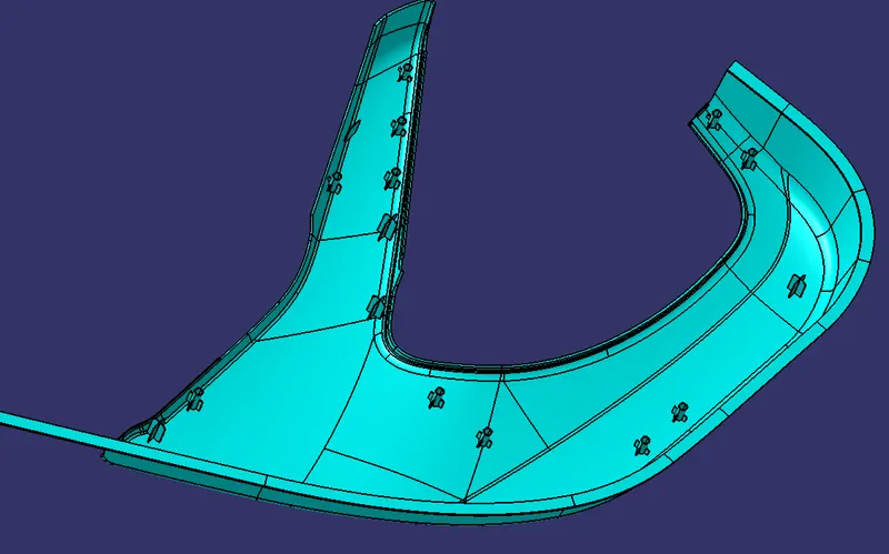
- Also, the height of all locators from fixing component surface should be same as all the locators must aligned at the same time.
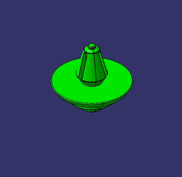
- Then we can move to doghouses. Here we have considered 3 dog houses with push pin clips.
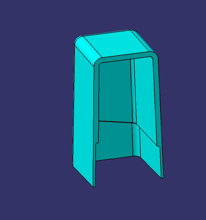
- For the push pin clip to be installed, certain slots and ribs are to be made in the dog house as shown below.
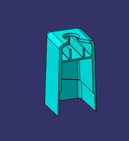
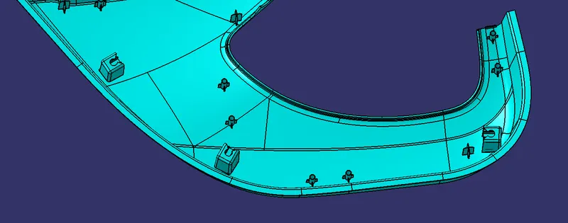
- Then, we can add all the engineering features to the main solid body using Boolean operations.
- Proper fillets should be given with appropriate values wherever required.
Modification To Components for Locating and Attachment Strategy:
- After engineering features are done, accordingly, clearance holes should be made for heat stakes and locators on corresponding component flanges as shown below.
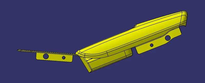
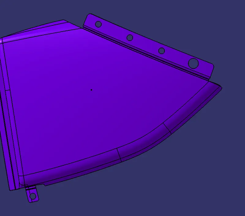
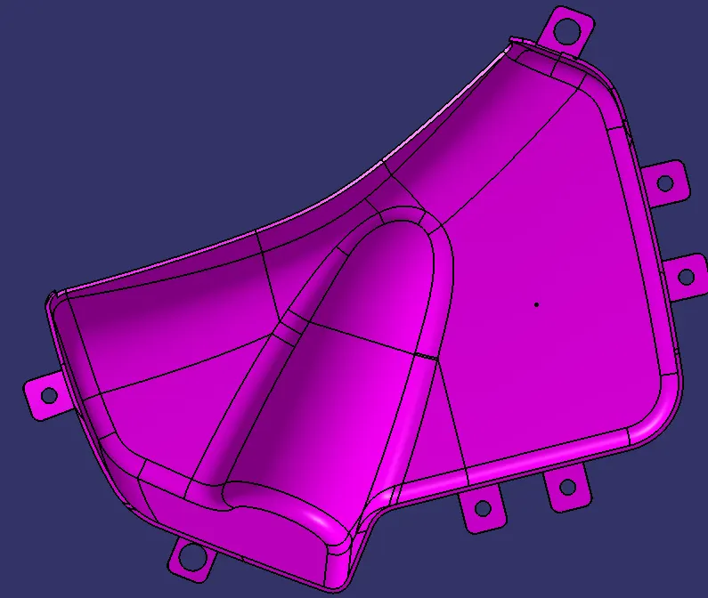
- The clearance for heat stake holes should be 0.5 mm per side while that for locator clearance holes should be 0.1 mm per side.
- It should also be noted that the inner walls of these clearance holes should be drafted with respect to the tooling axis by 0.5 degrees for proper alignment.
ASSEMBLY:
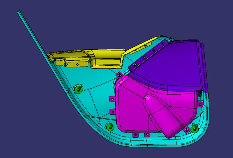
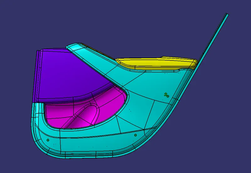
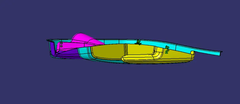
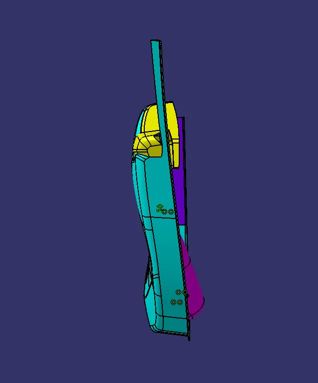
- For assembly of the parts, we already created the parts at positions so we can fix the Lower substrate.
- Then, for push pin clips, we take corresponding references points and axes on the dog houses and assemble them using proper constraints.
IMAGES SECTION:
ARM REST
Draft Analysis and Color Scale Variant
Main Tooling Axis
Class A Surface
Surface Body
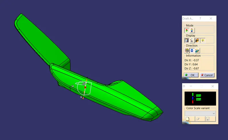
Final Solid Body
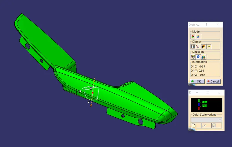
As you can see above we get positive results for draft analysis at 3 degrees draft angle.
Side Core Tooling Axis
Class A Surface
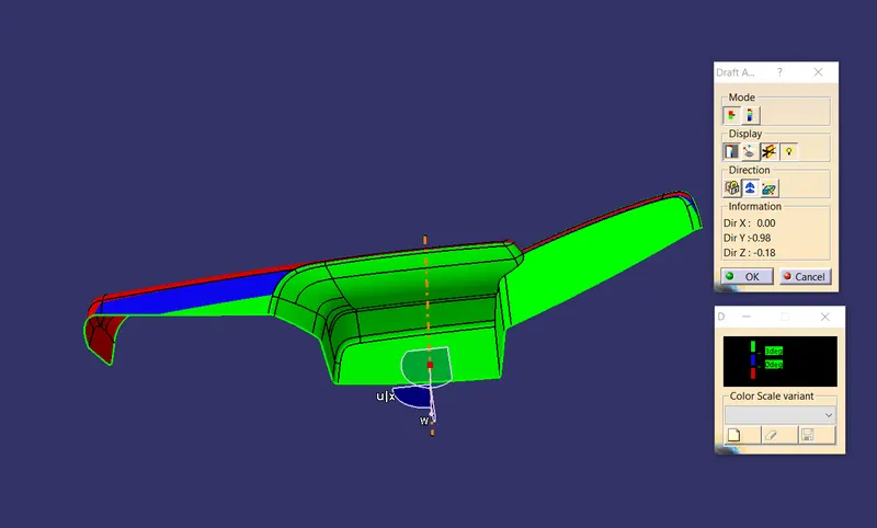
Surface Body
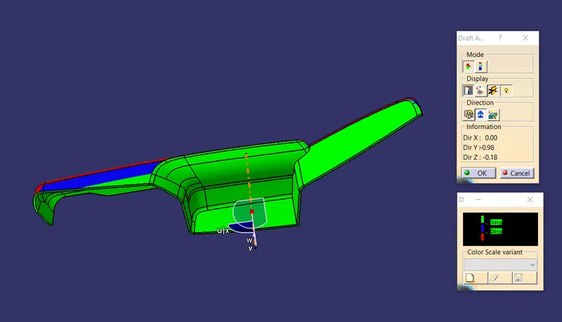
Final Solid Body
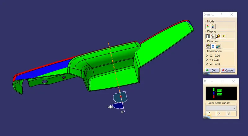
As you can see above we get positive results for draft analysis at 3 degrees draft angle.
DIFFERENT VIEWS
Surface Body
Front View
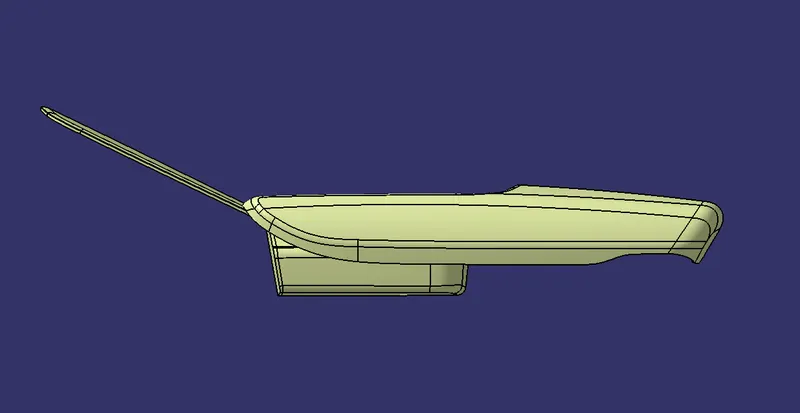
Top View
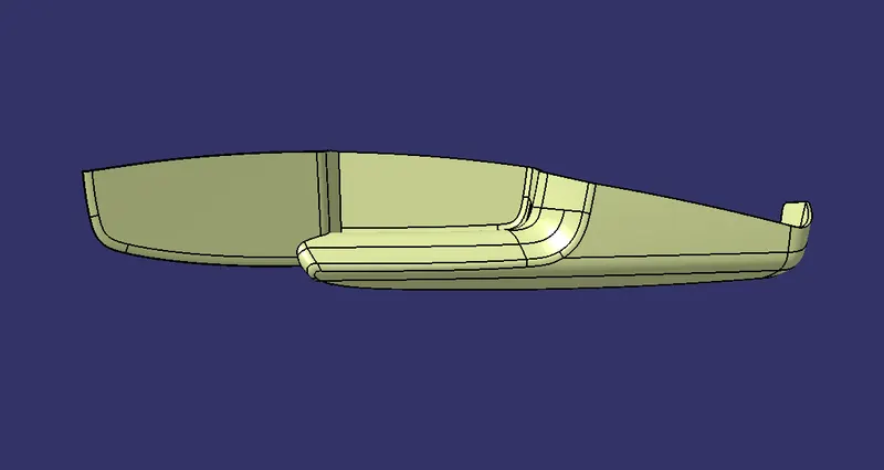
Side View
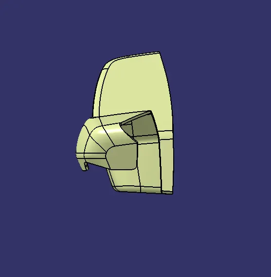
Isometric View
Final Body
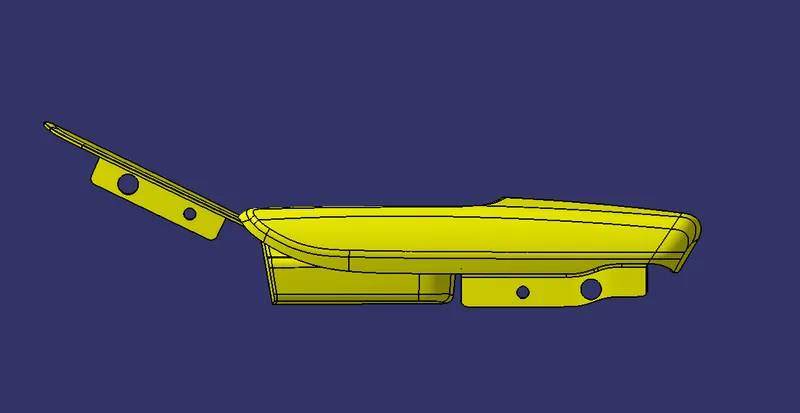
Front View
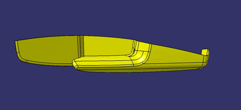
Top View
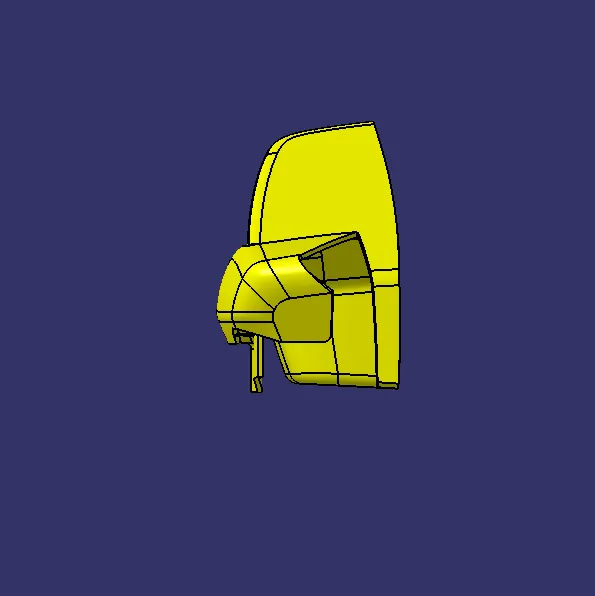
Side View
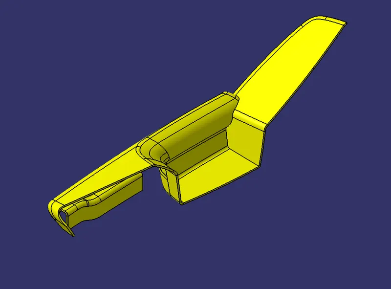
Isometric View
MAP POCKET 1
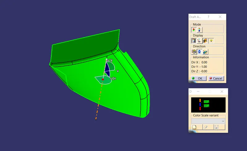
Draft Analysis and Color Scale Variant
Class A Surface
Surface Body
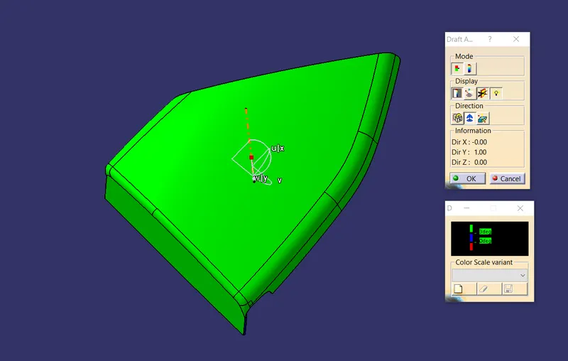
Final Solid Body
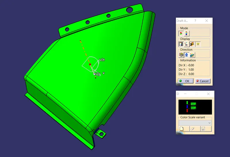
As you can see above we get positive results for draft analysis at 3 degrees draft angle with some regions having draft angle less than 3 degrees but acceptable positive draft.
DIFFERENT VIEWS
Surface Body
Front View
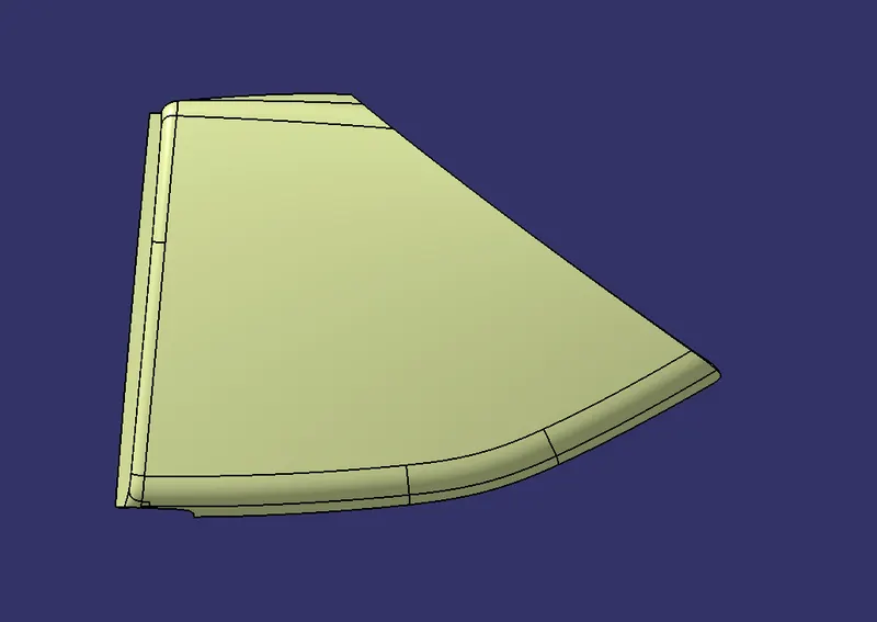
Top View
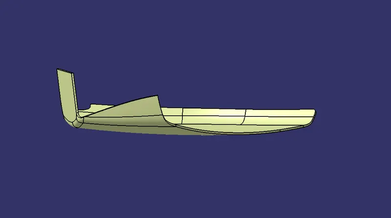
Side View
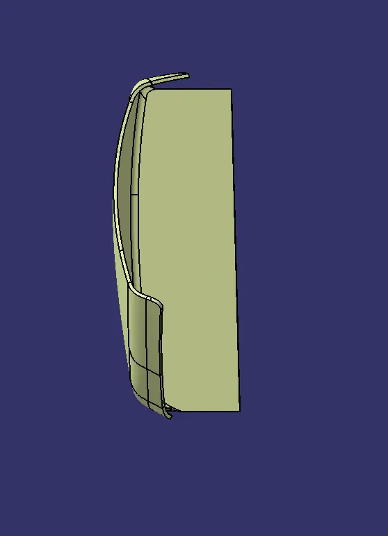
Isometric View
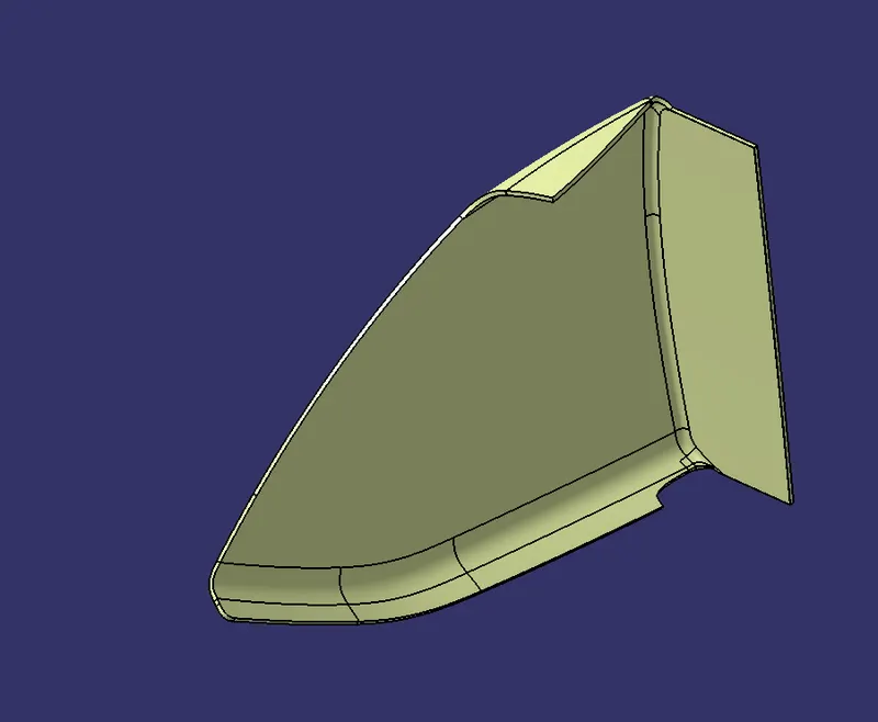
Final Body
Front View
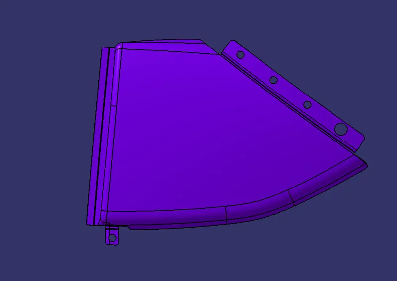
Top View
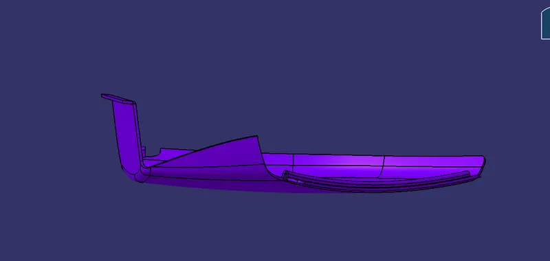
Side View
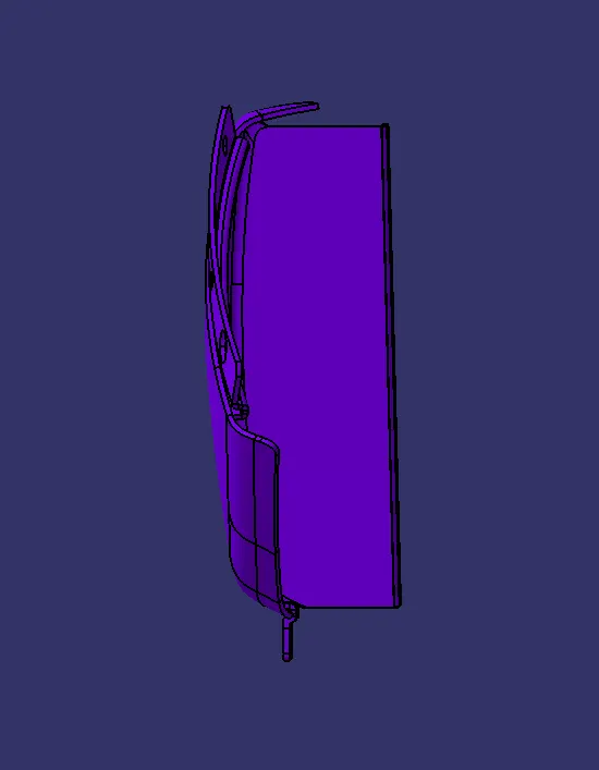
Isometric View
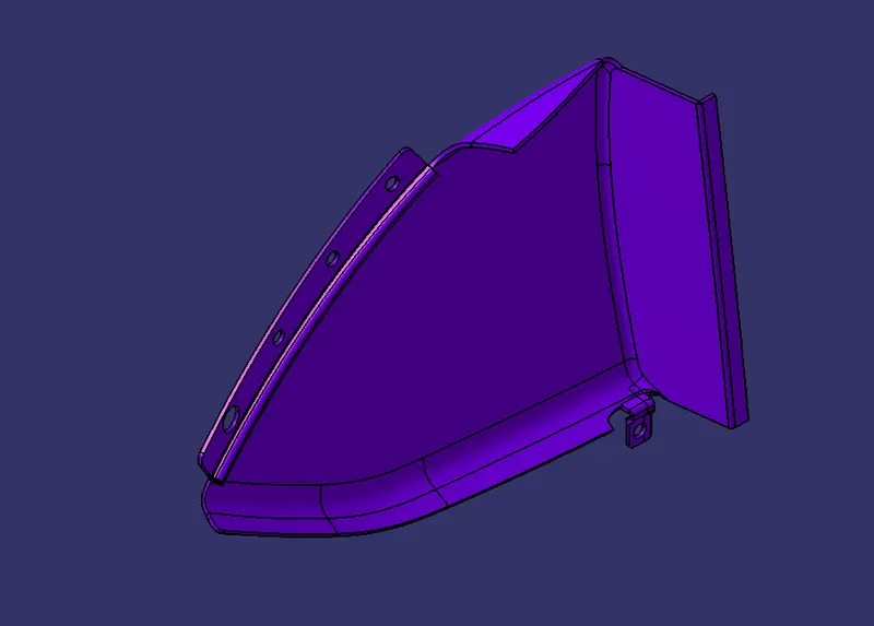
MAP POCKET 2
Draft Analysis and Color Scale Variant
Class A Surface
Surface Body
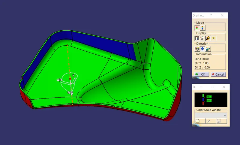
Final Solid Body
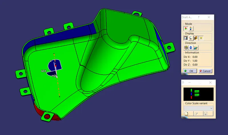
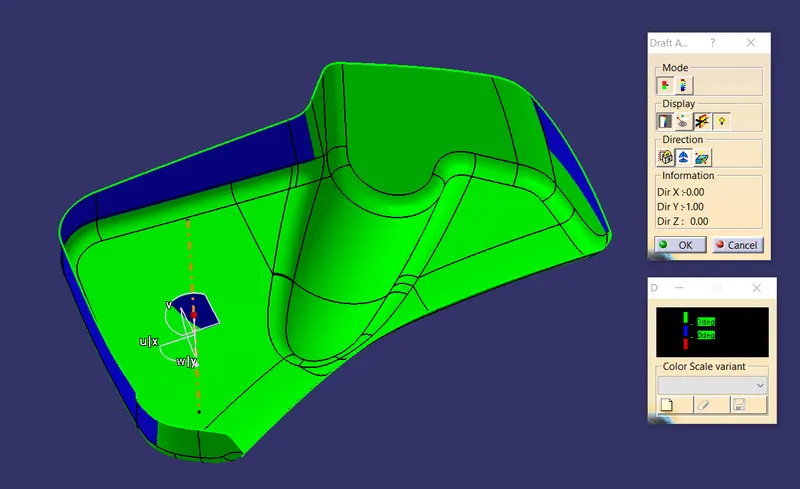
As you can see above we get positive results for draft analysis at 3 degrees draft angle with some regions in blue which indicates that the regions are along the vertical direction. Thus, modification in class A surface is recommended to avoid the minimum draft condition.
Clearance Holes
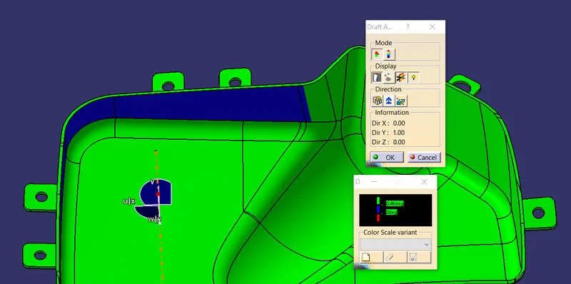
As you can see above we get positive results for draft analysis of the clearance holes at 0.48 degrees draft angle.
DIFFERENT VIEWS
Surface Body
Front View
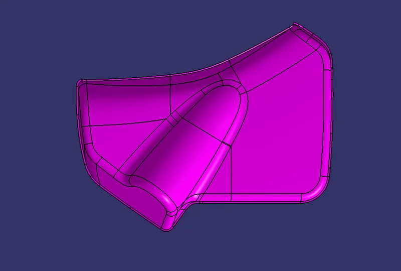
Top View
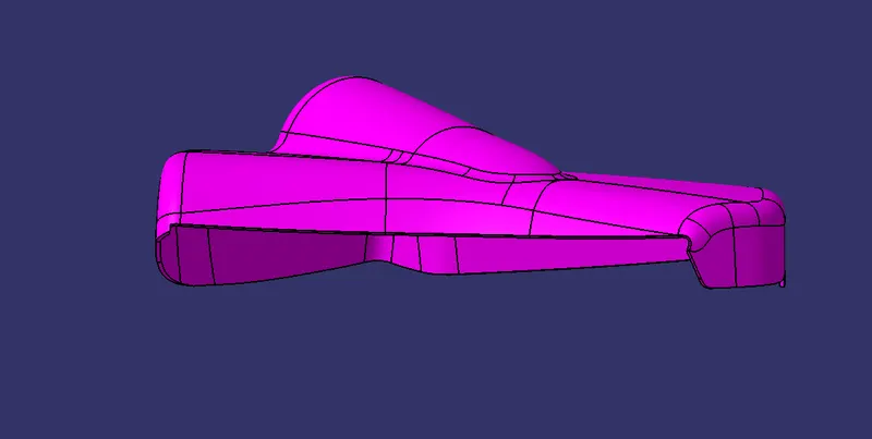
Side View
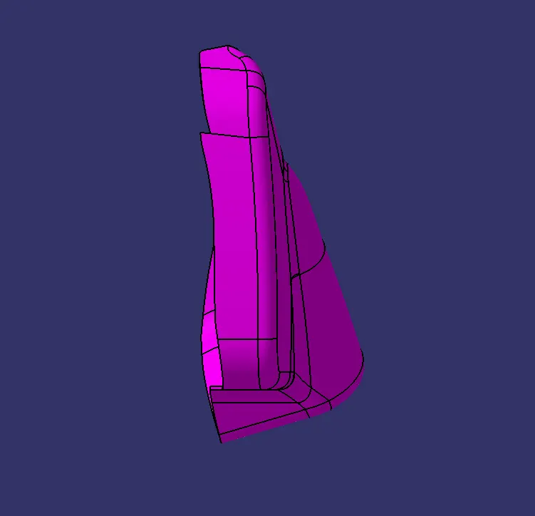
Isometric View
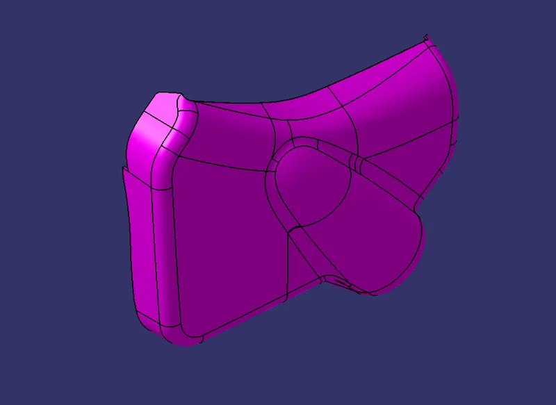
Final Body
Front View
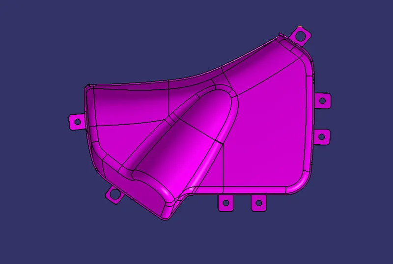
Top View
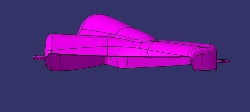
Side View
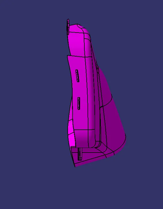
Isometric View
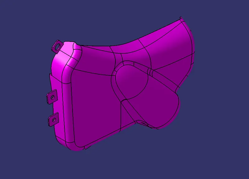
LOWER SUBSTRATE
Draft Analysis and Color Scale Variant
Class A Surface
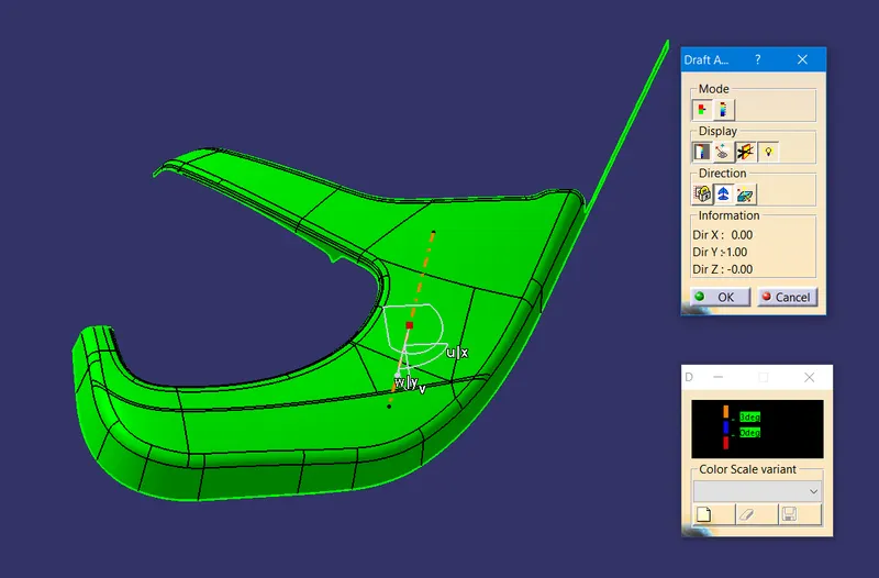
Surface Body
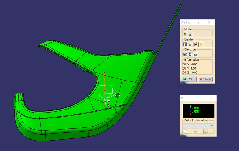
Final Solid Body
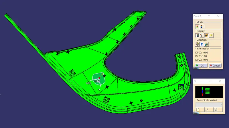
As you can see above we get positive results for draft analysis at 3 degrees draft angle.
Heat Stake
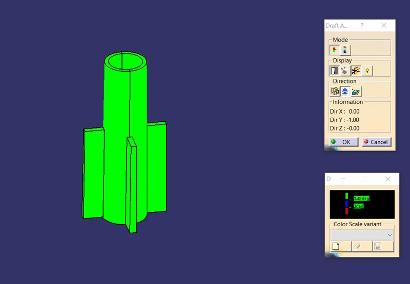
2 Way Locator
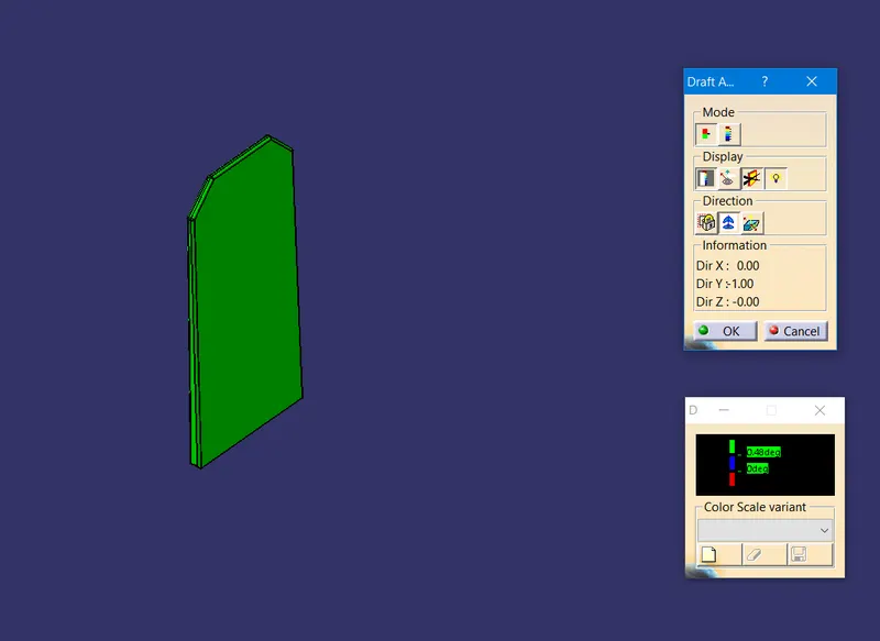
4 Way Locator
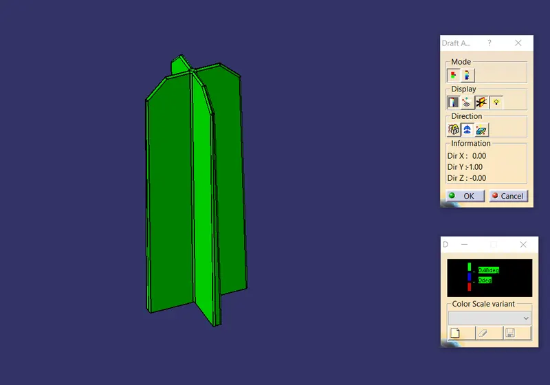
As you can see above we ge positive results for draft analysis of the heat stakes and locators at 0.48 degrees draft angle.
Dog House
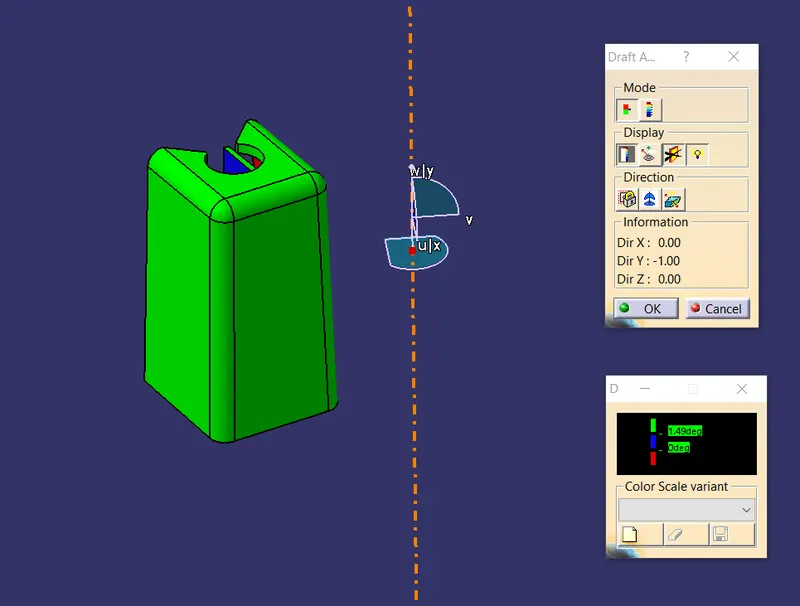
Main Tooling Axis
Lifter Tooling Axis
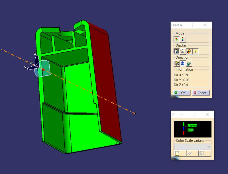
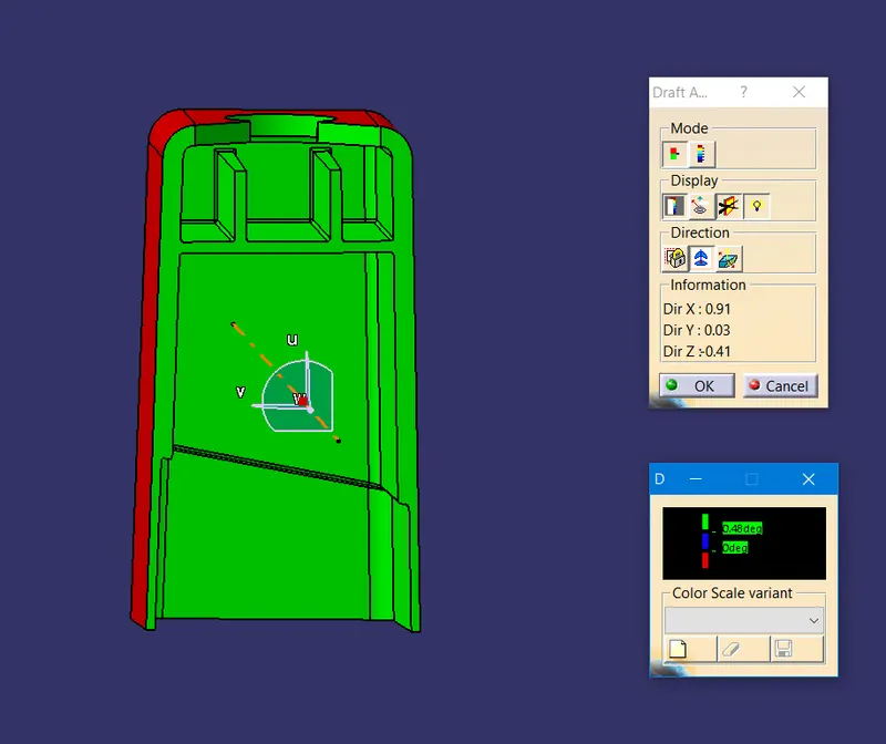
As you can see above we get positive results for draft analysis of dog house at 1.49 degrees along main tooling axis and 0.48 degrees along the lifter axis.
DIFFERENT VIEWS
Surface Body
Front View
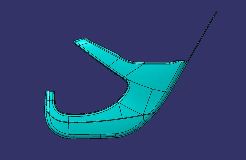
Top View
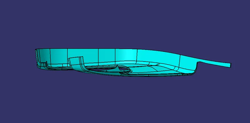
Side View
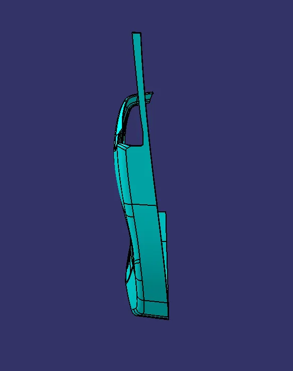
Isometric View
Final Body
Front View
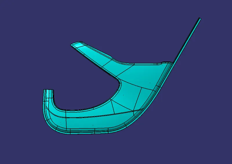
Top View
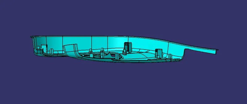
Side View
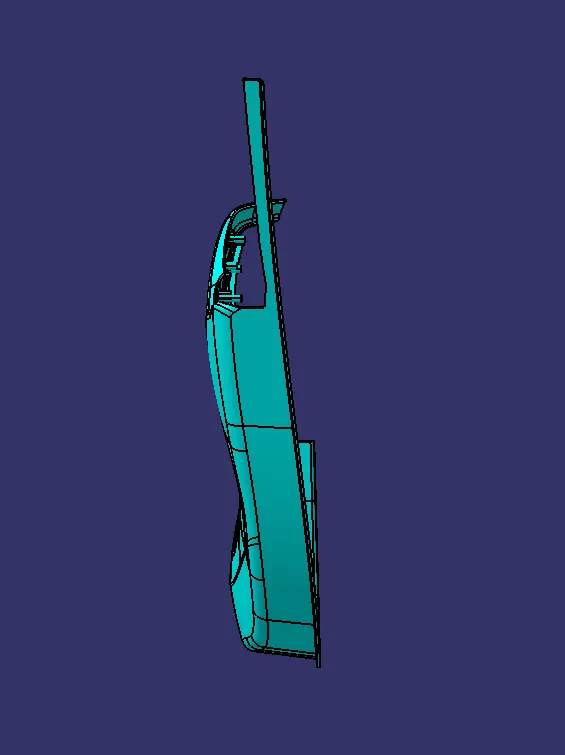
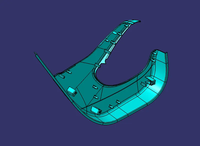
Isometric View
PUSH PIN CLIP
DIFFERENT VIEWS
Final Body
Front View
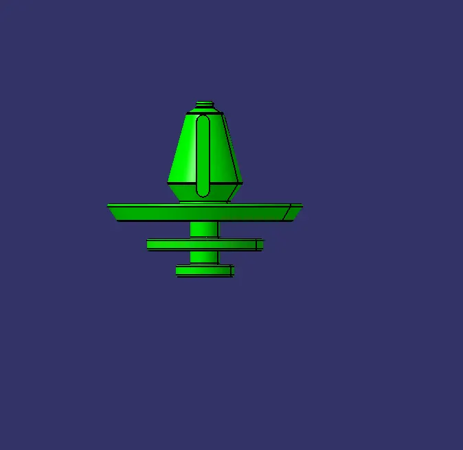
Top View

Isometric View
ASSEMBLY
Front View
Top View
Side View
Isometric View