Week 11 - Final project
PROJECT :- DESIGN AND DEVELOPMENT OF DOOR TRIM PANEL
Content :-
1) Objectives
2) Introduction
3) Requirements
4) Procedure
4.1. Splitting the individual Class A Surfaces
4.2. Creation of tooling Axis & Class A Draft Analysis
4.3. Creation of Class B Surface
4.4. Creation of Class C Surface
4.5. Creation of Solid Body
4.6. Draft Analysis of Solid Body
4.7. Creation of Attachment (B Side) Features.
4.8. Push Pin Assembly
5) Rendering of Final Door Trim Panel
6) Conclusion
1) Objectives :-
To create plastic door trim panel from given Class A Surface & attachment features using Master Section as per design guidelines & meeting the draft angle requirement along the specified tooling axis.
2) Introduction :-
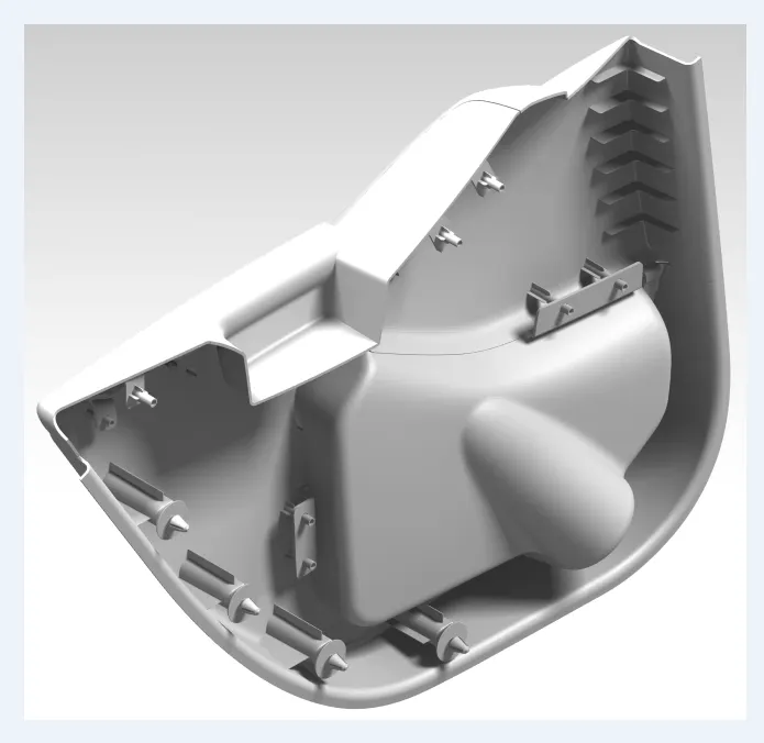
Door Trim panel is an automotive interior component attached to the inner side of the door. It is a vital module component that creates a more comfortable interior by providing most controls and decorative parts. The door trim panel also incorporates the other parts such as Arm rest, switches, or other controls for windows and the locking mechanism, convenience lights, audio speakers, storage compartments, and other features. In most cases the car door trim is attached to the door frame either by visible screws or B surface attachment features (push pin with dog house and Heat stakes).
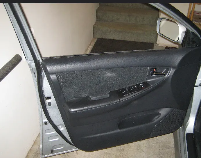
In modern cars typically the door trim panels are made of plastic most often using injection molding process.
Plastics
Plastics are the polymers that have the capability of being molded or shaped, typically by the application of heat. Plastics also incorporate other special properties such as low density, transparency, toughness & no electrical conductivity, which allows plastic to be used for making a wide variety of components.
Examples :- Bottles, Drums, door panels, etc.
Plastics are mainly divided into two types
01) Thermoplastics
These are most commonly used plastics, due to their ability to go through numerous melt and solidification cycles without significant degradation.
02) Thermosetting plastics
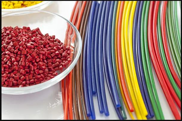
In contrast with the thermoplastics the thermosetting plastics or thermosets remain in permanent solid state after curing. Thermosets decompose upon heating rather than melting and will not reform upon cooling.
Some of the plastics that are widely used in automotive industries are
- Polypropylene
- Polyvinyl Chloride (PVC)
- Polycarbonate
- Acrylonitrile Butadiene Styrene (ABS) etc.
Advantages of plastics
- Light Weight
- Easily available
- Low cost
- Ease of manufacturability
- Good heat & chemical resistance.
- High strength & durability.
3) Requirements :-
Following are the requirements to create solid cad model of door trim panel
- Class A surface
- Nominal thickness - refer master section
- Attachment strategy.
The below image is of given Class A Surface for the door trim panel which includes master sections for the attachment features.

4) Procedure :-
4.1) Splitting the individual Class A Surfaces
*) The Given Class A Surface is an assembly of entire door trim panel
*) Extract them & split into individual parts & do the further process
*) The Door trim panel consists of following different part assembly that are
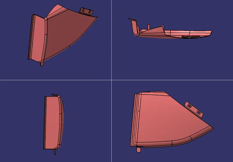
A) Lower Map Pocket
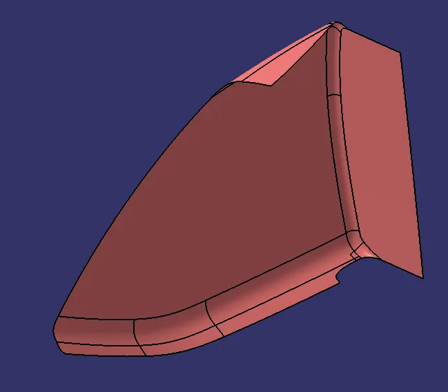
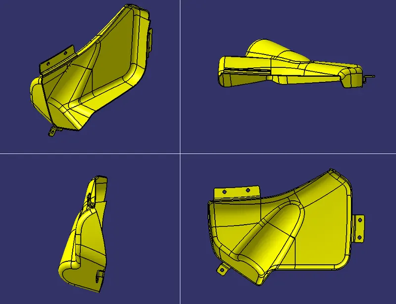
B) Upper Map Pocket
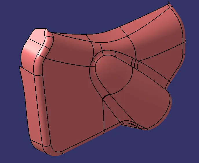
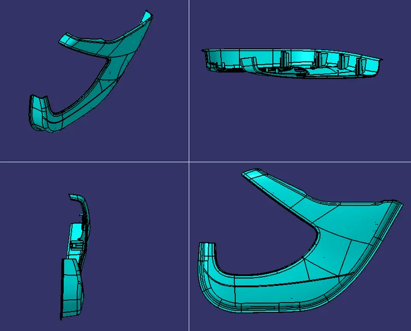
C) Lower Substrate
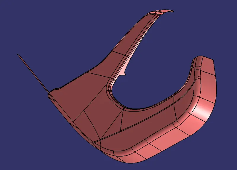
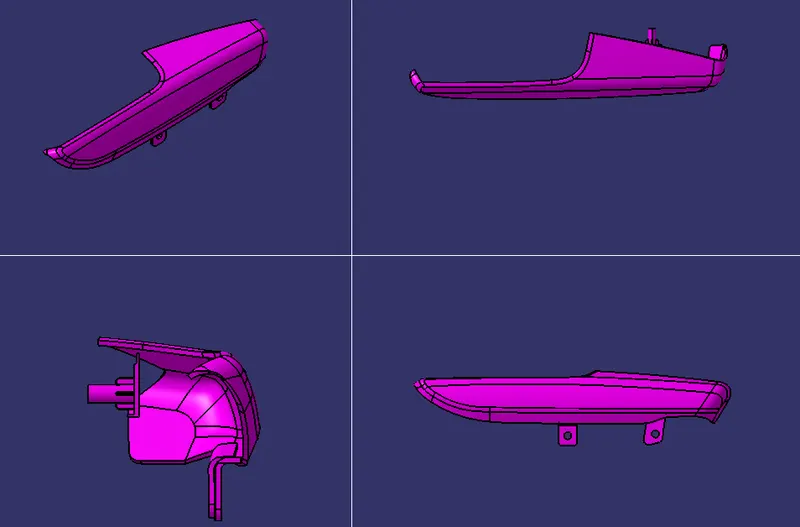
D) Armrest Body 01
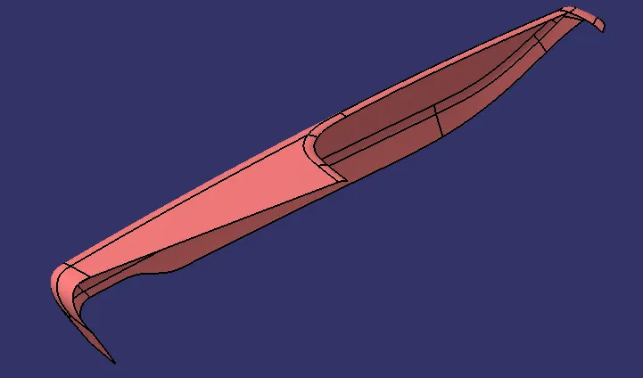
E) Armrest Body 02
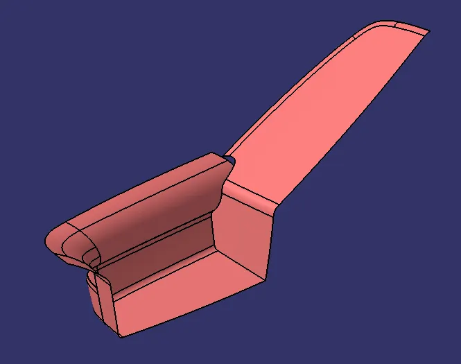
4.2) Creation of Tooling Axis & Class A Draft Analysis
*) Create tooling axis either by compass method or interaction method along which the Class A Surface meets the draft angle requirement.
*) Create Side core tooling axis if required.
*) Do the draft analysis for the Class A Surface along the tooling axis finalized.
*)Following are the images for draft analysis of Class A Surfaces.
A) Lower Map Pocket
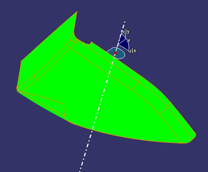
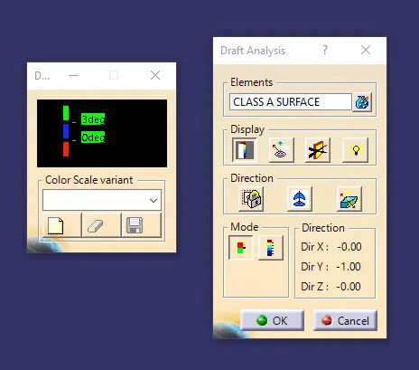
*) The Class A Surface of Lower map pocket meeting the draft angle requirement.
B) Upper Map Pocket
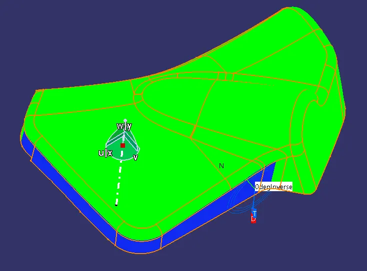
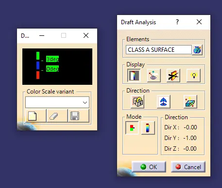
*) In the above image the blue coloured surfaces of the upper map pocket are parallel to the tooling axis, which is not meeting the draft angle requirement.
*) In such cases inform the Class A Surface Engineer to modify the surface and give the minimum draft angle for the surfaces.
C) Lower Substrate
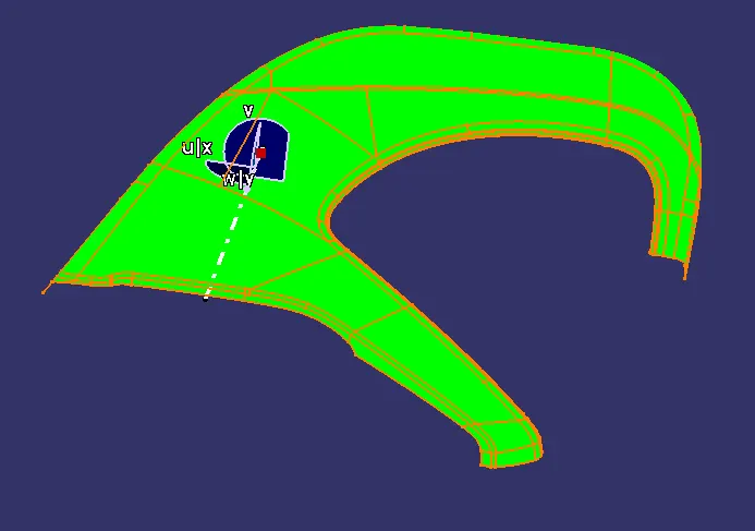
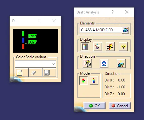
*) The Given Class A surface for the Lower Substrate part is meeting the draft angle requirement.
D) Armrest Body 01
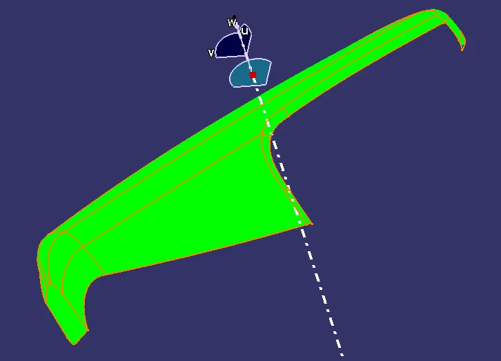
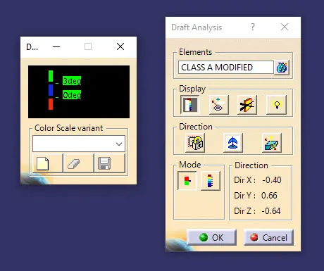
*) The tooling axis for this part is created by compass method.
*) The given Class A Surface is meeting the Draft angle requirement.
E) Armrest Body 02
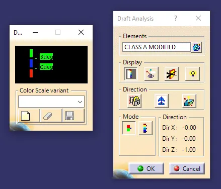
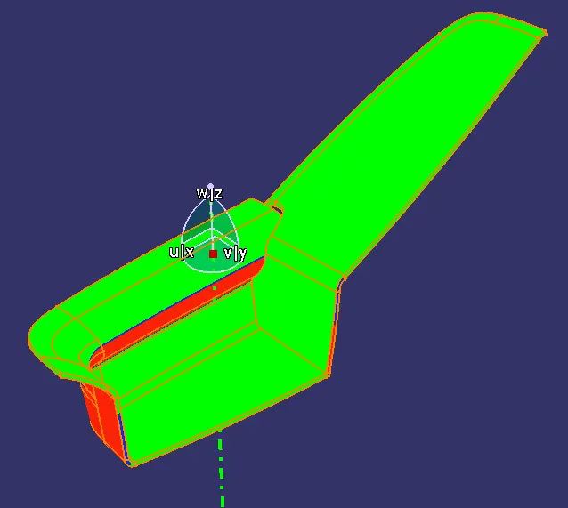
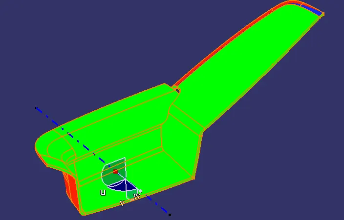
*) This part body cannot be cleared along single tooling axis and required side core tooling axis.
*) Draft Analysis along Main tooling Axis
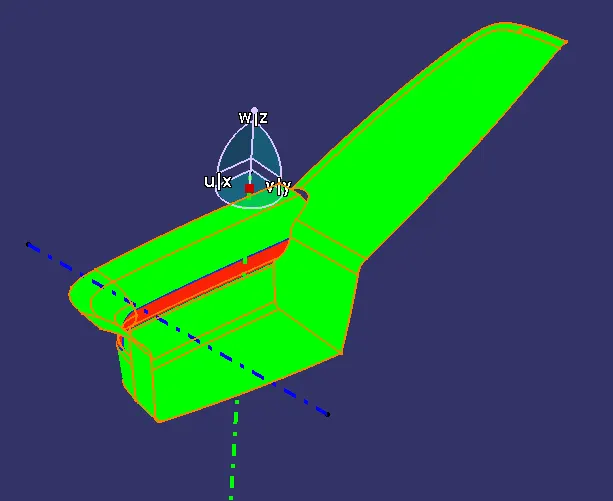 \
\
*) Draft analysis along side core tooling axis
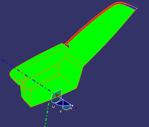
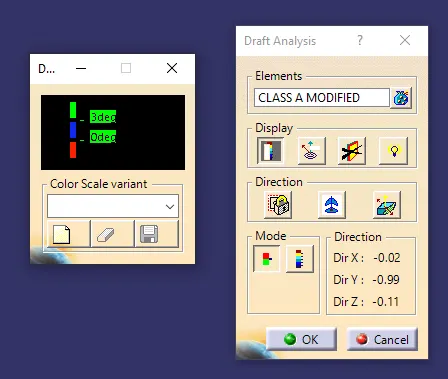
*) The given Class A Surface is meeting the draft angle requirement, the portion which is not clearing along main tooling axis is clearing along side core tooling axis.
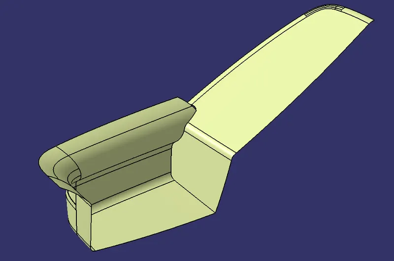
4.3) Creation of Class B Surface :-
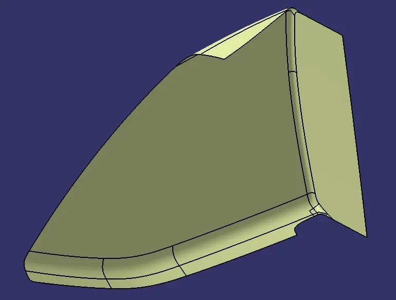
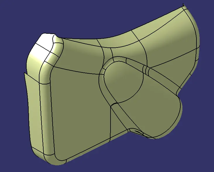
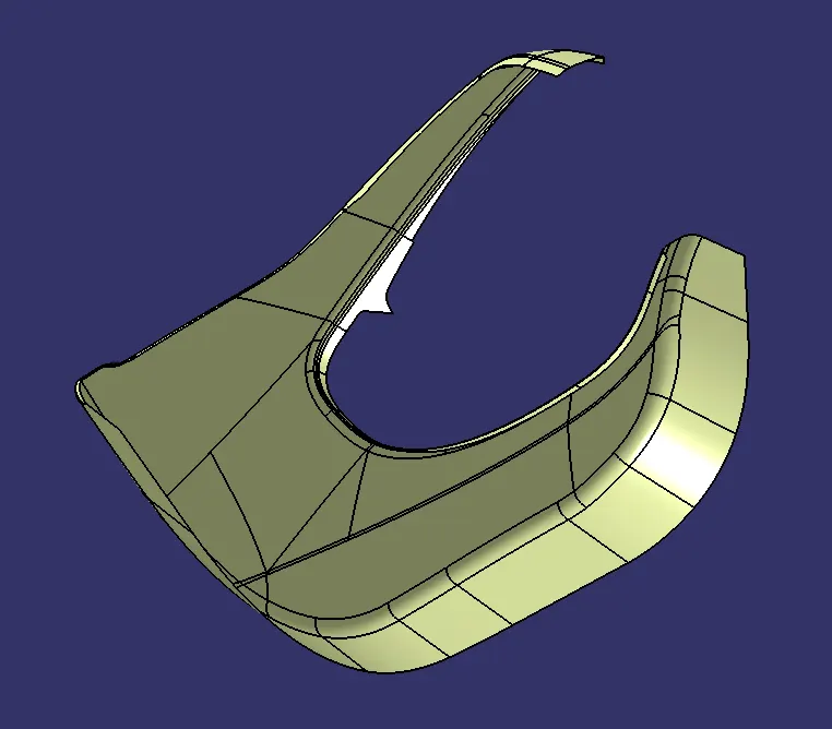
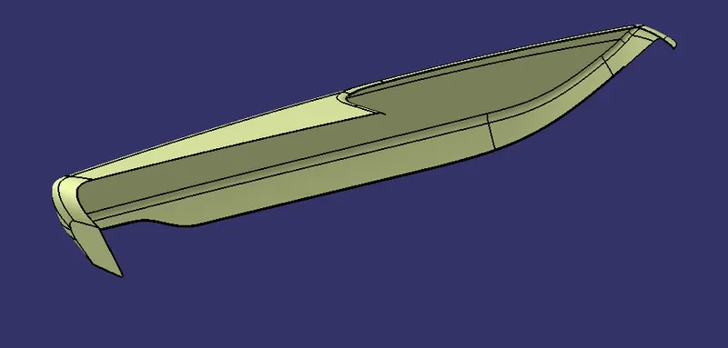
*) Create Class B Surface by offsetting the given Class A Surface with 2.5mm value and using other commands.
*) Following are the images of Class B Surfaces
A) Lower Map Pocket
B) Upper Map Pocket
C) Lower Substrate
D) Armrest Body 01
E) Armrest Body 02
4.4) Creation of Class C Surface
*) Create Class C Surface from Class A Surface and meeting the requirement of minimum draft angle.
*) Make sure the created Class C Surface is meeting the draft angle requirement along the specified tooling axes.
A) Lower Map Pocket
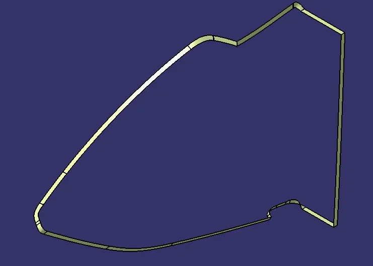
B) Upper Map Pocket
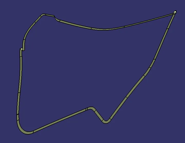
C) Lower Substrate
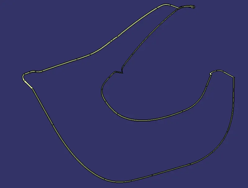
D) Armrest Body 01
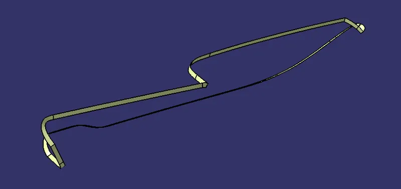
E) Armrest Body 02
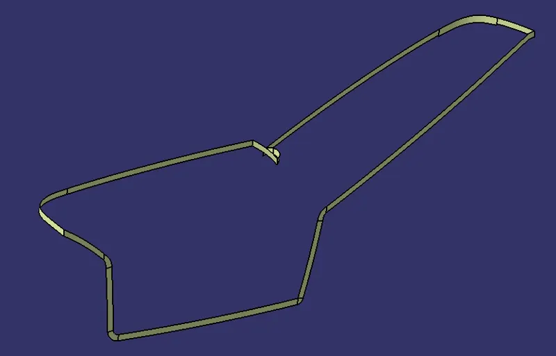
4.5) Creation of Solid Body
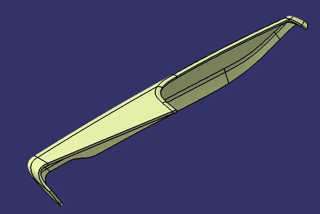
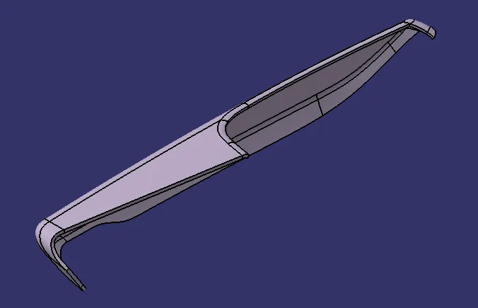
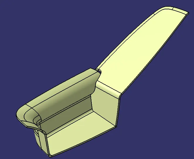
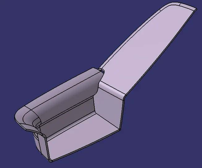
*) Join Class A & Class C Surface
*) Trim the Join body with Class B Surface to Get final plastic body
*) Check whether the body is closed or not by applying boundary condition, the closed body will not form any boundaries.
*) Goto the part modelling workbench and crate solid plastic bodies using closed surface command
*) Following are the images of Closed plastic bodies
A) Lower Map Pocket
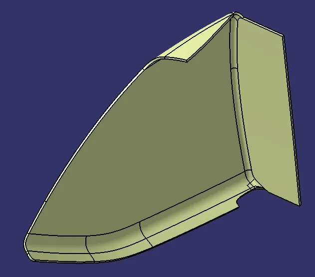
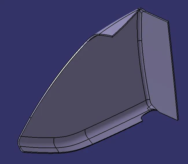
B) Upper Map Pocket
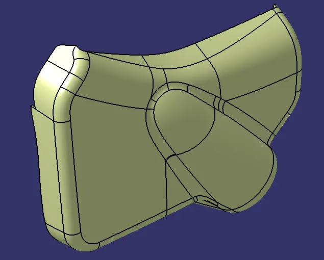
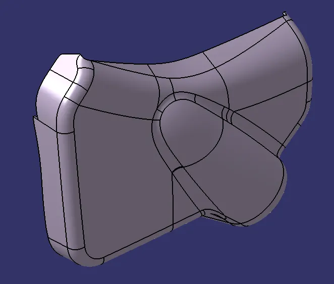
C) Lower Substrate
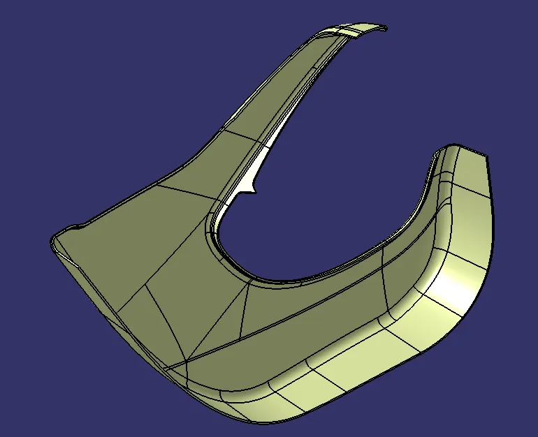
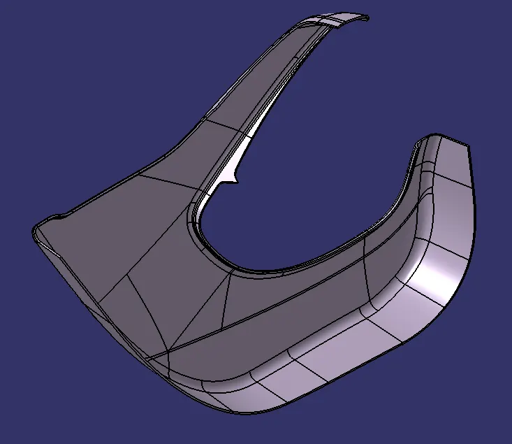
D) Armrest Body 01
E) Armrest Body 02
4.6) Draft Analysis of Solid Bodies
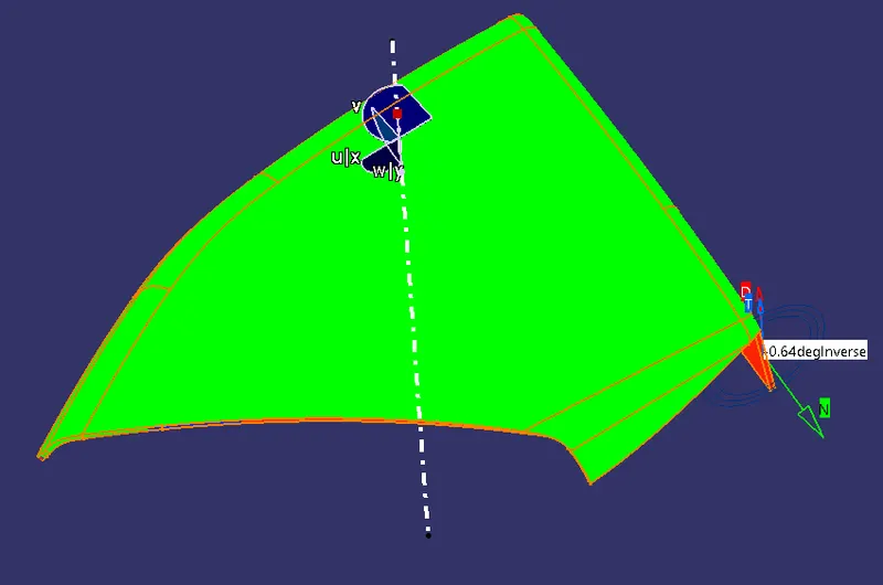
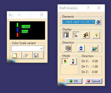
*) Do the Draft analysis for the created solid bodies along the specified tooling axis.
*) Check whether the entire body is meeting the draft angle requirement, if not correct it.
*) The Surfaces associated with the Class A which are parallel to the specified tooling axes cannot be cleared in the solid model also until modified.
*) Following are the images draft analysis for the solid bodies
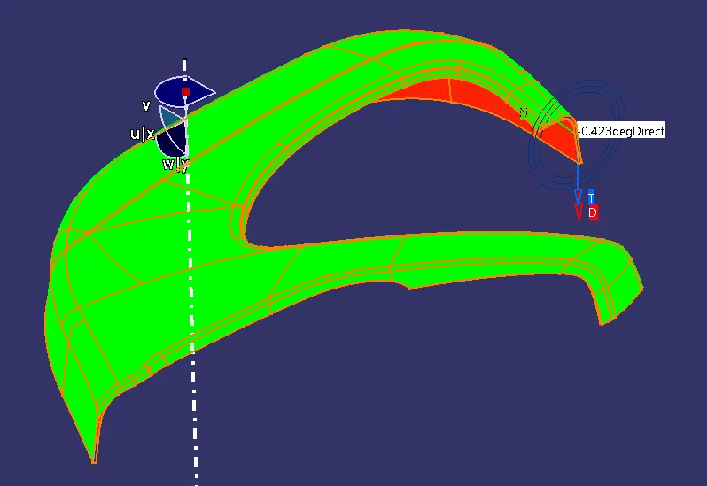
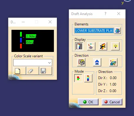
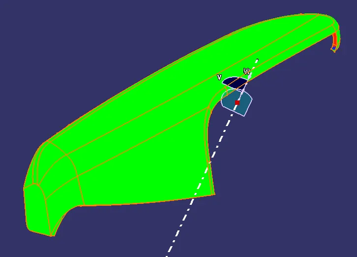
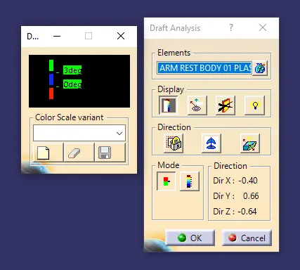
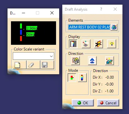
*) The Blue colour indicates the draft angle for the surface in between zero to min. Draft angle.
*) The Red colour indicates the negative value of draft angle and need to be modified.
A) Lower Map Pocket
B) Upper Map Pocket
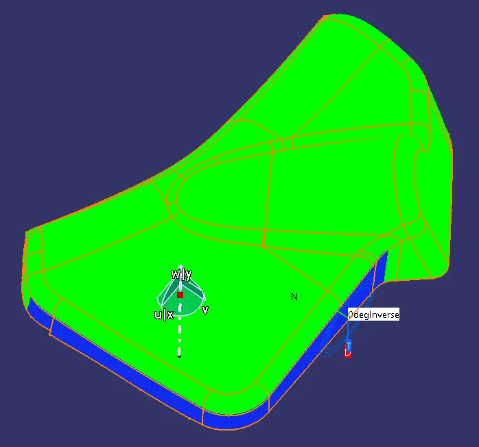
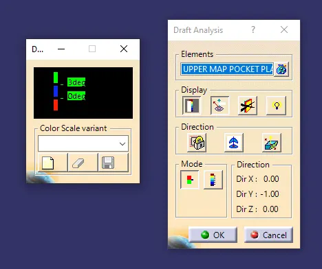
C) Lower Substrate
D) Armrest Body 01
E) Armrest Body 02
4.7) Creation of Attachment (B Side) Features
Introduction :-
*) The Attachment features are used to strengthen the plastic component and also to assemble or attach one part with the another.
*) Most Commonly used attachment features are
a) Ribs :-
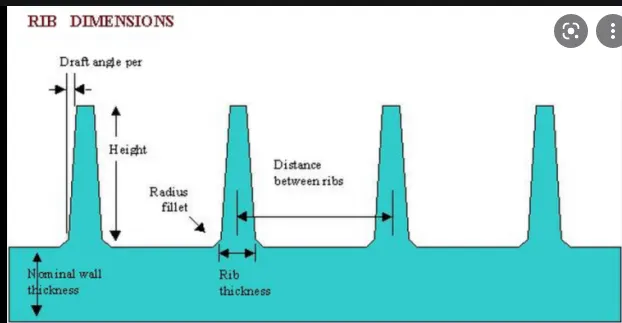
*) Ribs provide a stiffness & strength in the molded parts without increasing overall wall thickness
*) They also facilitate locating & arresting components in an assembly.
*) Also provide alignment in mating parts
Design Consideration for Ribs
- Thickness
- Height
- Location & Distance between ribs
- Draft Angle
- Manufacturability
b) Heat Stakes :-
*) While manufacturing a plastic component with thermoplastic material, it is often necessary to join a thermoplastic to a part of dissimilar material, whether it be a metal or dissimilar plastic material.
*) Thermal staking is an assembly method that uses the controlled melting & reforming of a plastic stud to capture or lock another plastic or metal component of assembly.
Advantages :-
*) Simplifies the machining process
*) Reduces the machining cost
*) Allows higher density of weld
*) Multiple Fastening Points
c) Locators :-
*) Locators help in fixing or arresting degrees of freedom of a part with another part in an assembly.
*) It also provides alignment in the assembly
*) While designing make sure the tip of all the locators are at the same distance from the surface to which it is connected
Design Considerations :-
- Thickness
- Height
- Draft Angle
- Chamfer & Fillet at the entry corners.
d) Dog House :-
*) Dog houses are used where the need of screw boss or push pin or any other attachment feature at a longer distance from B Surface.
*) It also helps in avoiding sink marks on the plastic component.
*) If the height of the dog house is too long rib can be attached for the support
Design Considerations :-
- Wall Thickness
- Height
- Thickness at the Bottom
- Draft Angle
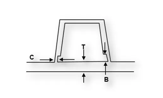
- T = Component thickness
- C = Thickness at the bottom - 0.4T
- B = 3.0 to 6.0mm
- Width at the top = min 12mm
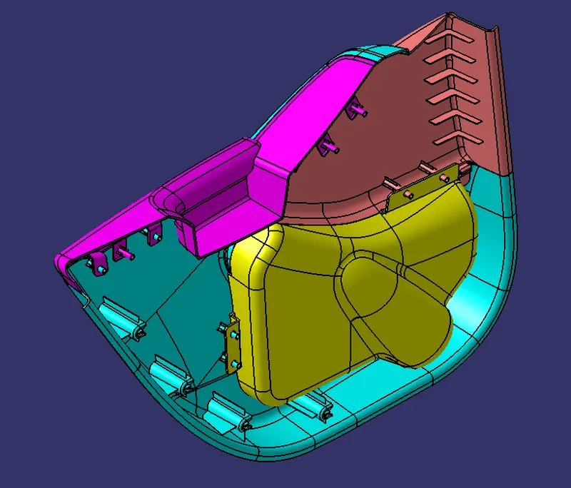
Creation of Attachment Features
*) Create the B side or attachment features as per the design guidelines.
*) Follow the master Section for attachment feature creation.
*) Create heat stakes for attachment of one parfait with the another
*) Create Dog house with the proper height
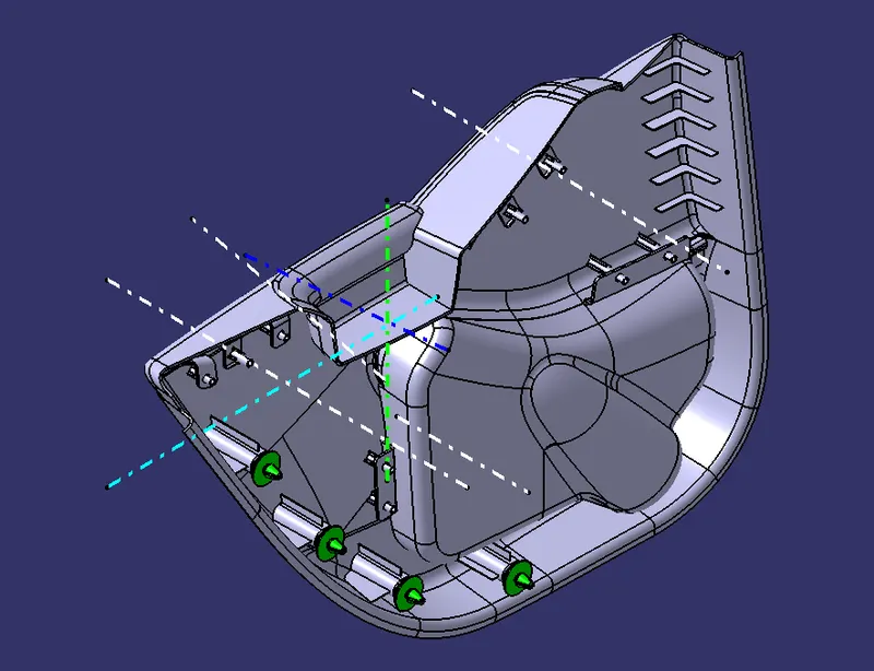
*) Dog house creation need separate tooling axis as the internal parts of it cannot be created using single tooling axis
*) Make sure the created attachment features meeting the draft angle requirement.
*) Assemble them with the main body.
*) Following image shows the attachment features created in this component
4.8) Push Pin Assembly :-
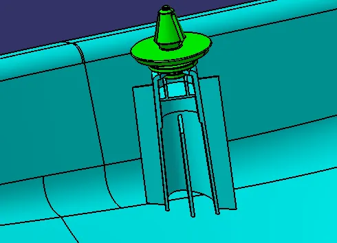
*) Push pin is a temporary attachment feature that helps in fixing a component in an assembly, and can be removed whenever needed.
*) Assemble the push pin on the top face of the dog house by the use of commands like Coincide constraint & Contact constraint.
*) Following image shows the push pin attached to the dog house
View Modes
A) Lower Map Pocket
B) Upper Map Pocket
C) Lower Substrate
D) Armrest Body 01
E) Armrest Body 02
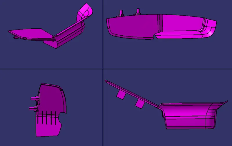
5) Rendering
6 Conclusion
Design and development of car door trim panel with attachment strategy is done using given class A surface & master sections and also draft analysis done for the final component.