Week 11 - Final project
AUTOMOTIVE DOOR PANEL - PLASTIC PRODUCT DESIGN FOR INJECTION MOLDING
Objectives:
- Study and analyze the given class A surfaces for recognising the Plastic parts.
- Create thickened part of door panel using the given master sections for reference
- Create the mounting features as per design guidelines in the industry and with master sections
- Draft analysis & Tooling analysis
- Check for tooling feasibility
Introduction:
This project is a combined form of almost all studies conducted for plastic product design. Here i received some class A surface patches of a automotive door of main plastic elements. My aim is to generate solid plastic product parts from those surfaces which are feasible for manufacturing and assembling together as a single product. Class B and C surfaces will be maid accordingly including flanges and other features. Solid parts are to be closed and will be analyzed for draft angles. Proper attachment features will be provided as instructed by referring the master sections given.
Software used: DS CATIA P3 V5 2018
Workbenches used:
- Generative shape design
- Mechanical Part design
- Part assembly workbench
Input datas:
Class A surfaces and master sections:
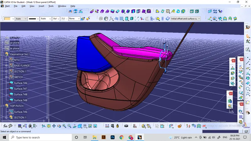
List of plastic parts:
- Arm rest
- Lower substrate (Main element)
- Upper map pocket
- Lower map pocket (Bottle holder)
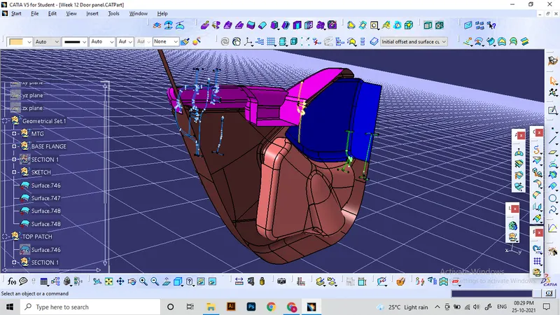
Arm rest:
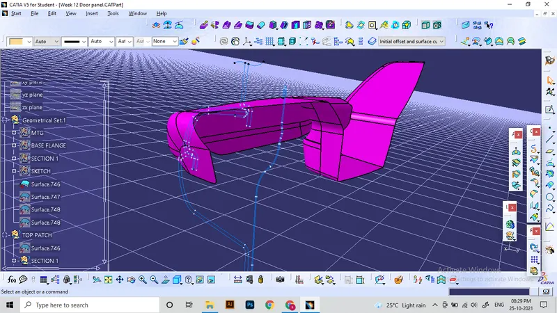
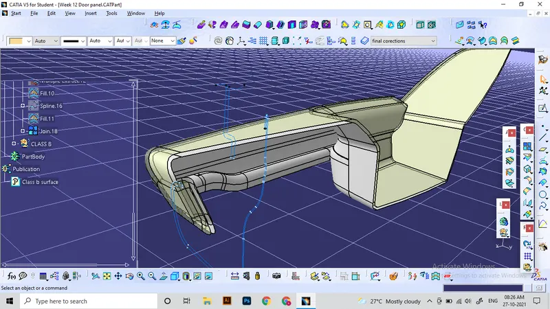
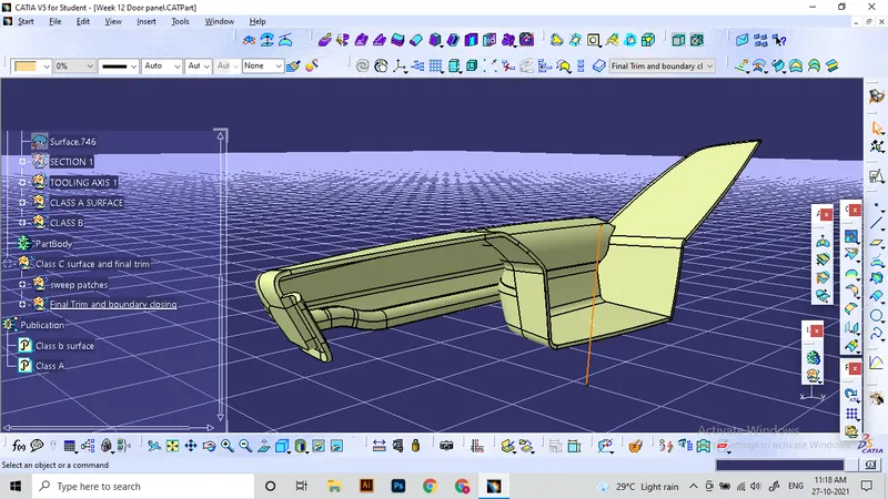
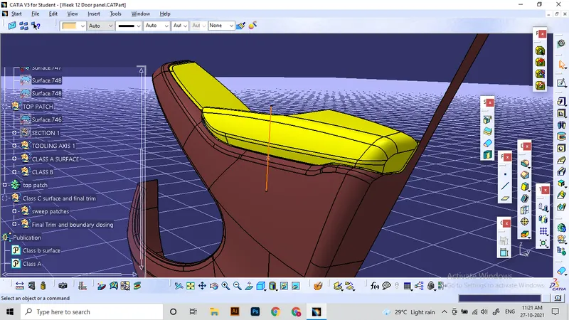
According to the master sections given, Arm rest has included 3 surface elements. This individual part have a covering of leather of or any aesthetic material. The top layer is a marking for the wrap. The surfaces which needs for the product design are the class A and class B. these will be made using the offseting method from the given surface.
Thickness of part: 2.5 mm
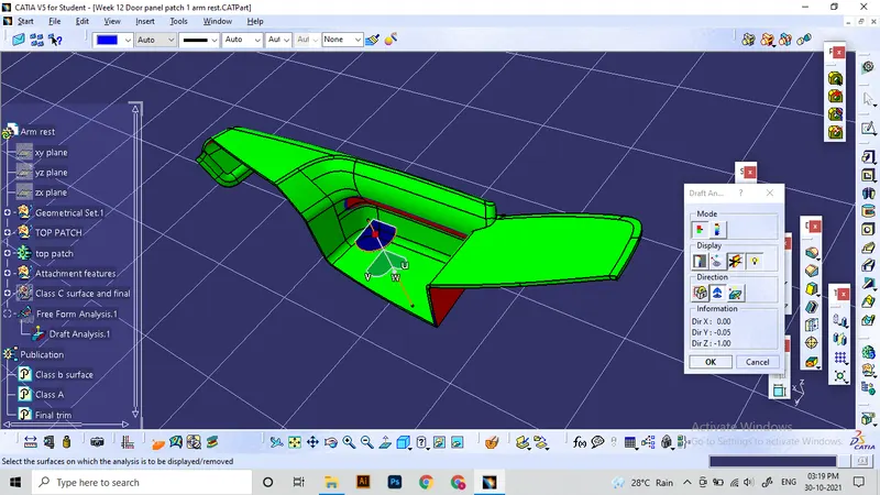
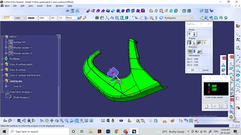
Draft analysis for class A surface:
- Initial draft anlysis is conducted for finding the feasibility of the design for manufacturing.
- For main elements, A minimum draft angle of 3 degree is taken as acceptable range.
- Areas which are not cleared using the main tooling direction, will be cleared with side cores or reworked for ensuring feasibility.
Surface modelling:
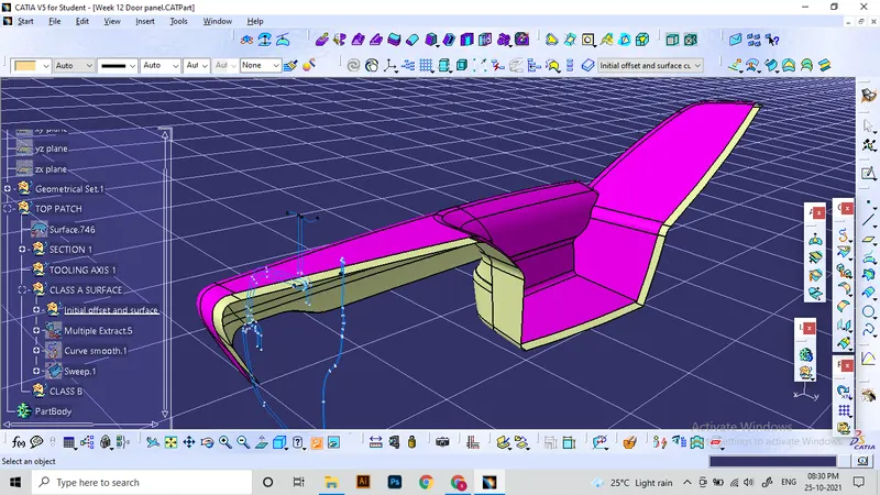
Extra flanges and extensions will be provided for assembling operations.
Lower substrate:
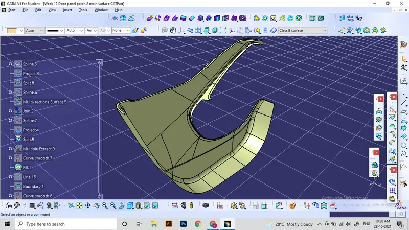
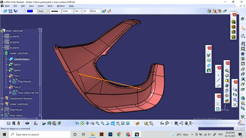
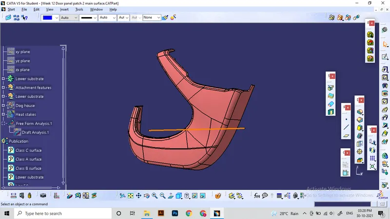
It is the main element in this project. Lower substrate have the largest area of all elements and it will be made from comparatevely stronger plastic material. All other 3 elements are coming in contact with this element. So the lower substrate will be acting as parent for the other 3. Those elements will be attached to the main substrate. So lower substrate will have largest number of attachment features. To make a basic solid part, we use the general approach of Class B and C surfaces.
Draft analysis for class A:
Upper map pocket:
This is an aesthetic element which used to fill the open areas of door panel. These elements can be utilised for mounting any systematic features on the back side. Some areas will not have any functional advantages but essentially they will be crutial parts by appearance.
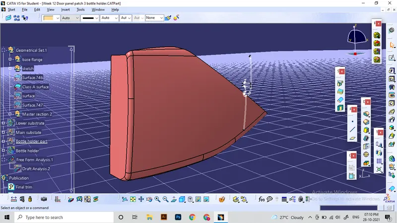
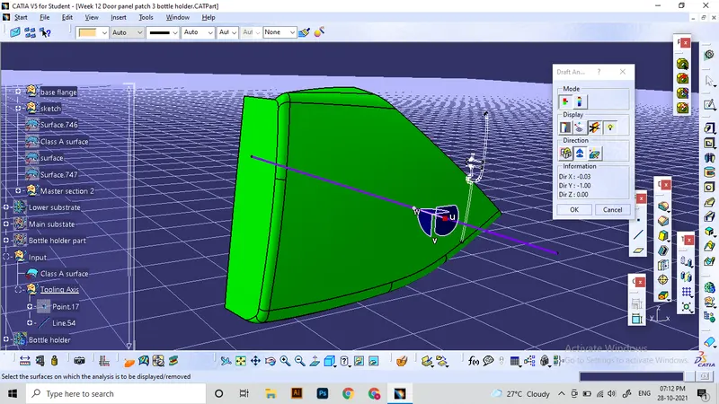
Surface draft analysis:
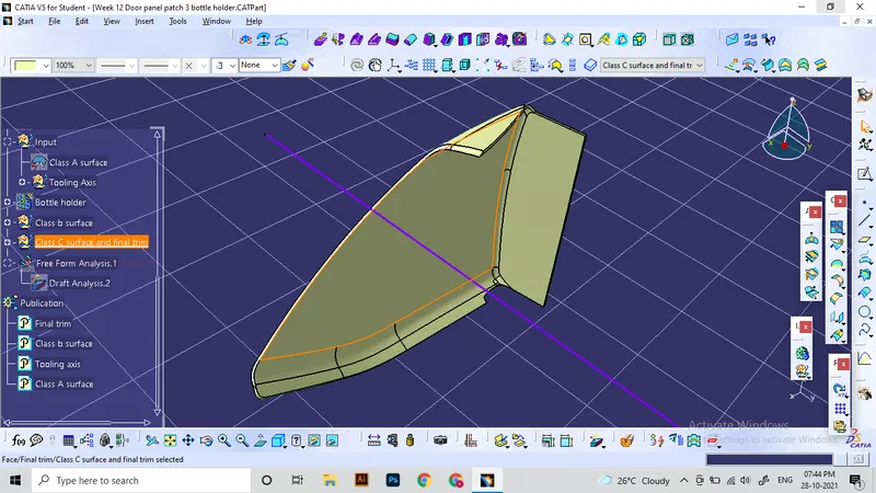
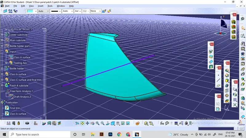
Solid model:
Bottle holder:
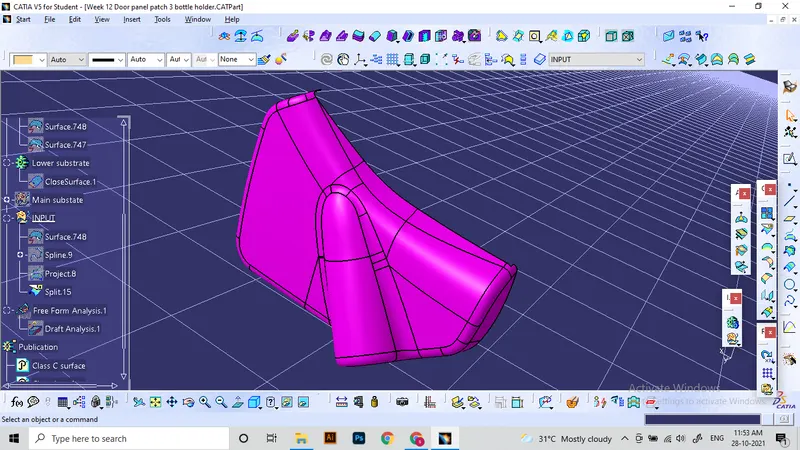
Draft analysis for class A:
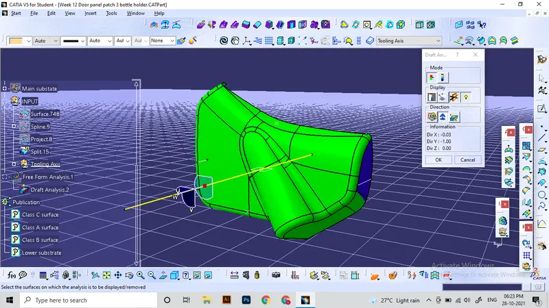
Solid model:
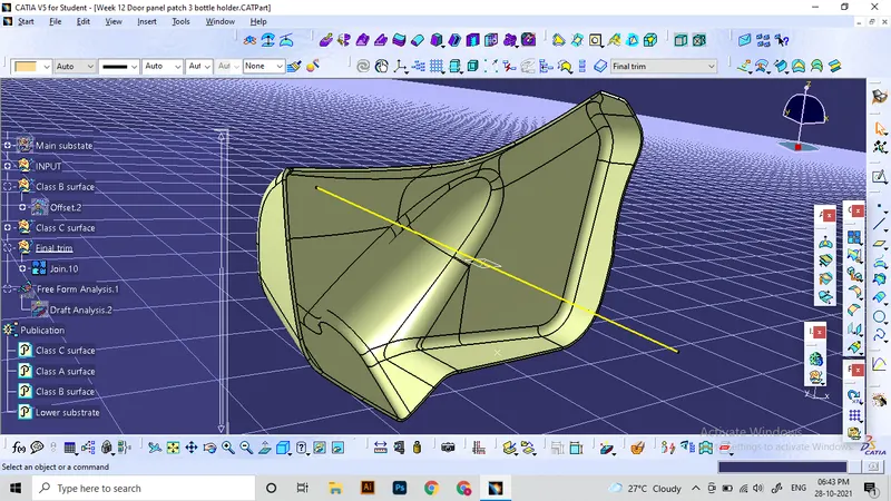
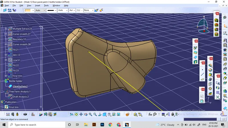
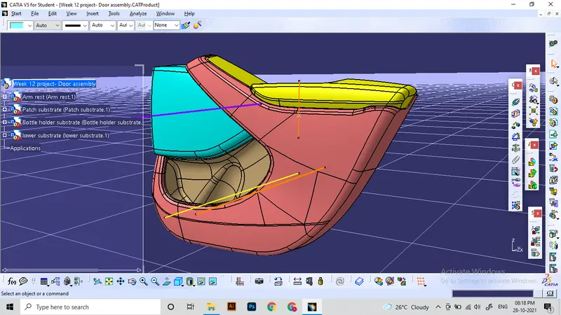
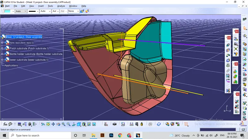
Door panel part assembly in Assembly workbench:
Attachment features:
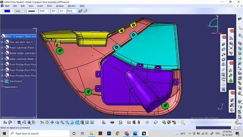
Attachment strategy used for this assembly is an industrial standard procedure. We will be using the lower substrate as parent element which all 3 other components are incorporated. The features used are as follows:
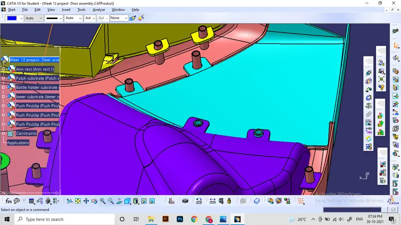
- Use Push pin with Dog house for Lower substrate – To connect with the sheet metal elements
- Use heat stakes for part to part attachment
All elements are made on the class B side of components which does not affect the appearance from front side. Draft angles will be provided on every surfaces for tooling feasibility.
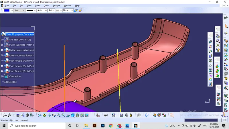
Heat stakes:
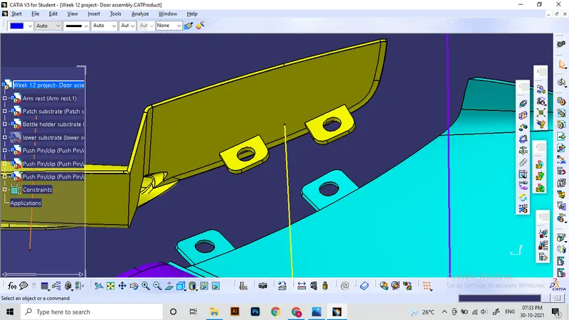
Heat stakes are hollow cylindrical projections given to the solid parts. These can be helpful when joining materials which have similar material properties. The projected parts will be heated and melted to join with other part. For this application, it needs to provide flanges or extensions on the other element and also the holes at proper positions to match with the location of heat stakes.
In this case, i will be adding heat stakes on the lower substrate and flanges on the other elements.
Flanges:
Assembled view:
Dog house with push pins:
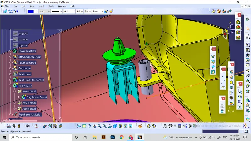
Push pins are a type of attachment part which helps to lock an object to position by using only pushing force. Push pins are used for temporary joints which enables it to remove when required.
For our application, The lower subatrate have a concave shape on the class B side. So for installing push clips, we need to make dog houses. It also helps to extend the positioning of the push clip accordingly.
Main wall thickness for dog house: 2 mm
Since push clips will be attached on dog house, it is necessry to provide extra support inside the dog houses. It can be done by adding ribs.
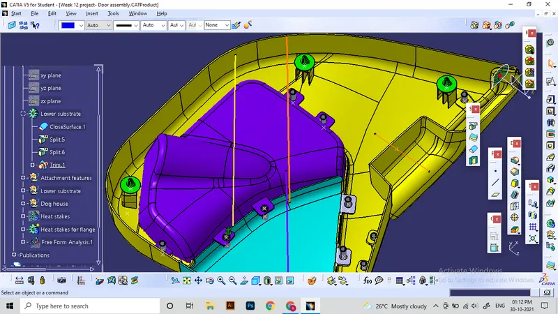
Final Assembly after Finishing the solid addition and union trimming operations:
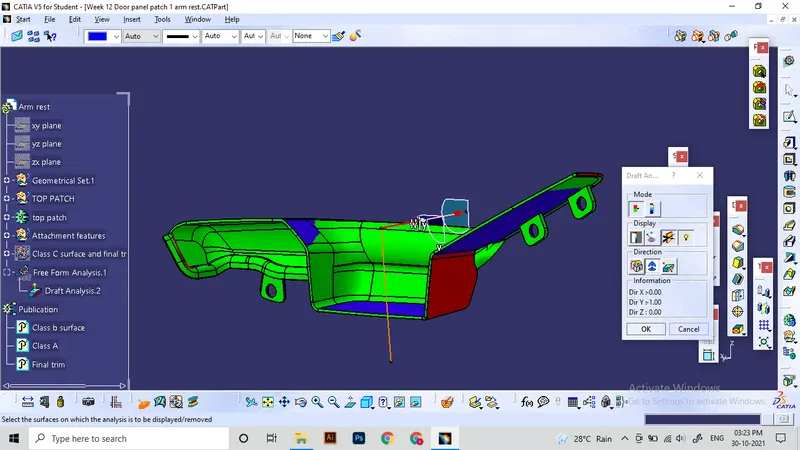
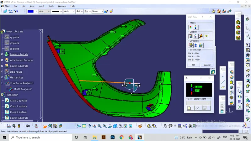
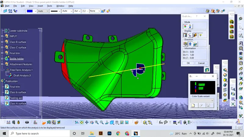
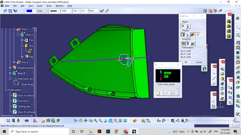
Final Draft analysis:
At last Draft anlaysis is again conducted for Solid model and B side features.
Draft angle provided for B side features: 0.5 degree
For arm rest, analysis is done on the side tooling axis. Others are conducted on their respective tooling axes.
Conclusion: The required Solid surfaces are generated using Catia software as per the given master section datas. Additional engineering datas are implimented to solve the attachment requirement. By this project i'm able to study and practise plastic product development in catia using proper industrial standards.