Week 11 - Final project
AIM OF THE PROJECT:
- To Design and Development of Car interior door using the Catia V5 tool with the given class A suraface along with the given master sections.
- Also we need to create the B side features of the door component as per the design rules and which the draft analysis of the component with the angles.
OBJECTIVE:
- To create the Thickned part using the master sections reference.
- Creating the Mounting Flanges given on the master sections as per design guide lines which will be used in the industries.
- After creating the thickned body and mounting flanges as per the design rules need to conduct the draft analysis and tooling analysis of the interior car design door which should follow the desogn considerations.
INTRODUCTION:
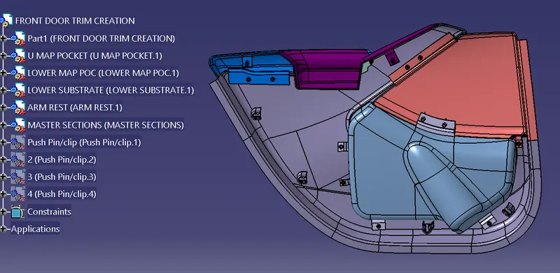
The door panel is the interface between interior car and inner working of the door, Generally the interior car door part can be divided into 4 major components called, LOWER MAP POCKET, UPPER MAP POCKET, LOWER SUBSTRATE, AND DOOR ARM REST, SWITCH BEZAL.
These requires one of the toughest requirements among the interior design of the car trimming operation. This should be designed to with stand the load being less then 2mm thickness of the interior car design door component which also protect the occupant during the collision.
Automatic Plastic In Today's Date;
Plastics represent only about 10% of the weight of today’s vehicle but about 50% of the volume. Many modern car interior parts are made with polymer, including lightweight seats, instrument panels, durable upholstery, sound control fabrics, the headliner, dash, and door panels.
Instrument Panles:
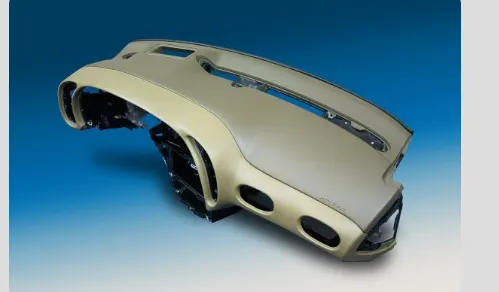
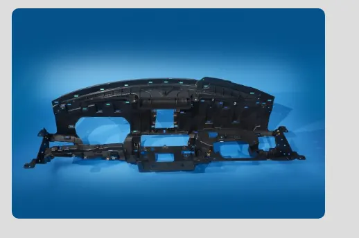
Thanks to modern plastics technology, instrument panels are often made of acrylonitrile-butadiene-styrene (ABS), ABS/polycarbonate alloys, polycarbonates, polypropylene, modified polyphenylene ether (PPE) and SMA (styrene-maleic anhydride) resins. These plastics allow for complex designs in items such as airbag housings, center stacks for instrument panels, and large, integrated instrument panel pieces.
Wholly integrated single-piece units can be manufactured from all-urethane and all-polypropylene resins. This results in a seamless instrument panel with greatly reduced NVH levels, molded-in color and with significant cost savings for the manufacturer. Cost effective post-consumer and in-plant recycling are also achievable.
This 2017 Lincoln Continental instrument panel is claimed to be the thinnest full-size, deep-draw injection molded IP in North America at 1.9 mm/0.07 in. This design was 14% lighter and saved money in materials investment.
Interior Lightning:
For safety and convenience, lighting in daylight and at night must be adjustable.
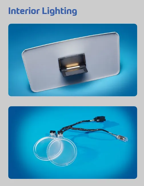
Plastic LEDs and acrylic fiber optic light tubes help make controls and instrument panels more readable.
Navigating is easier with overhead dome lighting and backlit buttons and knobs.
Plastics’ use in safety door lighting helps alert oncoming cars of stopped roadside vehicles.
The 2015 Lincoln MKC patented interior lighting application takes advantage of the optical transparency of a specialty polymer and geometrically mirrored surfaces to move the light in an innovative and efficient manner upward from the bottom of the cup holder.
Door Panels and Consoles:
Polymer materials are well suited for flexible, innovative and unique designs; resulting in stylish, comfortable, scratch-resistant durable interior components.
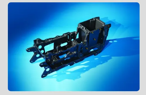
Plastic has revolutionized the design of car interiors, especially the doors and consoles. ABS, polypropylene and SMA plastics shape lightweight, durable and complicated shapes for consoles. Consoles include armrests, cup holders, and storage spaces. They would be difficult to reproduce as efficiently and with the same performance results using any other family of materials. Plastics help reduce noise, vibration, and harshness in the vehicle interior.
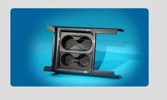
Cup holders are a focal point for customer critiques of vehicle interiors and they must accommodate a wide range of container sizes without tipping during normal driving conditions. According to industry awards, the 2017 Ford Super Duty Truck incorporates a living hinge making it adjustable to accommodate many containers while reducing 10 parts to 3. The vehicle also features a quad-barrel convertible cup holder, a design allowing the console to convert from two cup holders and a bin into a four cup holder console.
Plastics door modules can save time in production and assembly. The 2014 Chevrolet Corvette features innovative door trim technology reliant on plastics. Thanks to a thermoplastic polyolefin material specifically developed for this application, the result is a door-trim skin/foil that offers lower abrasion and less scratch & mar, resulting in reduced cost and weight.
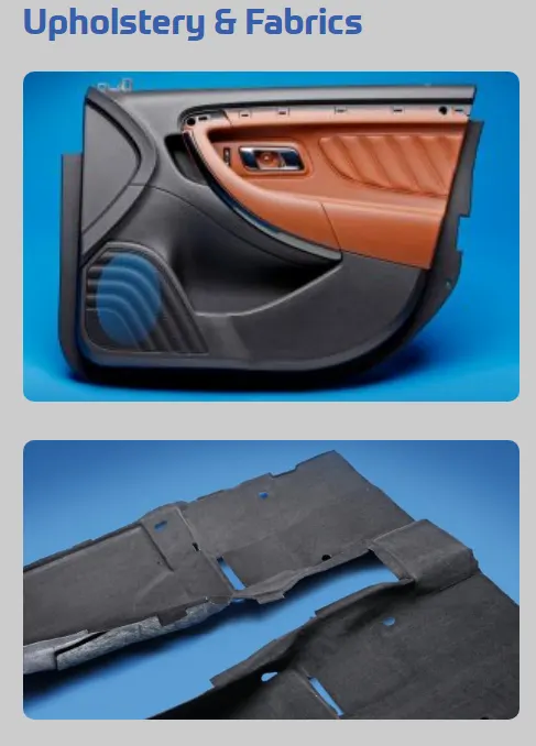
Upholstery and Fabricks for Door Fitting:
Design flexibility, corrosion resistance, and favorable mechanical properties make polymer composites a logical choice for upholstery and interior surfaces. Consumers demand surfaces with a high-quality look and feel.
Plastic car interior parts can provide similar aesthetics to natural materials with best-in-class scratch resistance for interior seats and surfaces. For example, many manufacturers are using artificial leather in automobiles owing to cost efficiency, aesthetic appeal, and other benefits.
The 2015 Ford F-150 features seat fabric made from a hybrid blend of 100% recycled materials, including post-industrial fiber and post-consumer water bottles. Use of the fabric provides significant environmental benefits, including diverting what’s reported as over 5-million water bottles from landfills each year.
Conventional seat construction can limit rear-seat legroom. The 2017 Chevrolet Bolt EV has an ultra-thin innovative design. The Bolt uses an all-plastic shell with a larger concave region for more occupant comfort. Chevrolet found that plastics technology reduced seatback thickness by 2 inches and mass by 6-8 pounds.
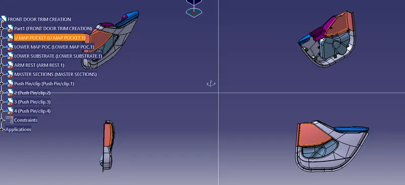
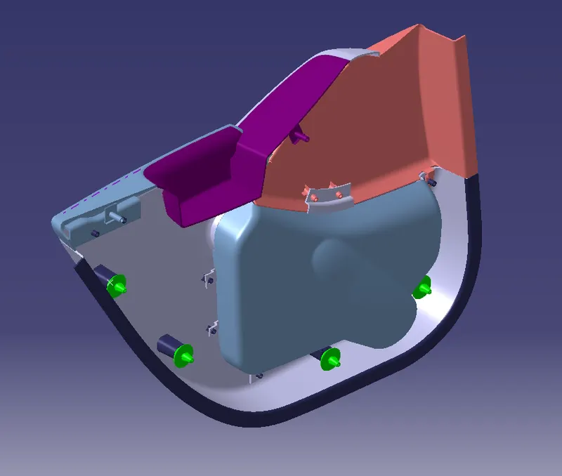
Door Trim Creation Final Isometric View:
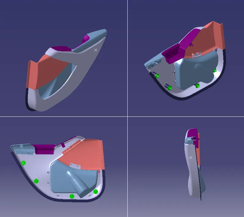
Multi Views Of Door Trim Creation:
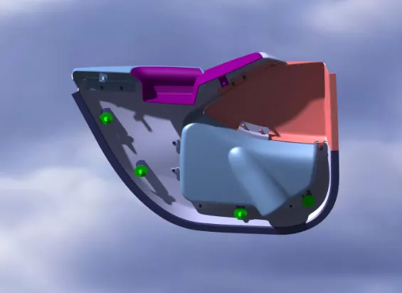
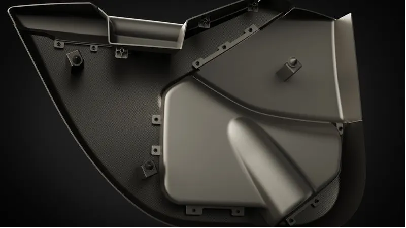
Rendering of Door Trim Panel:
METHODOLOGY FOR CREATION OF INTERIOR DOOR TRIM PANEL AS FOLLOWS:
- Tooling Axis Creation.
- Class B Surface creation.
- Class C Surface creation.
- Closed Body Creation.
- B side Features Creation.(like Heat stakes,Ribs, Locators, Dog house,pushpins, Mounting flanges etc)
- Draft Analysis of the component.
Given Data For Creating The Interior Door Trim Panel.
Class A Surface for All parts of Door Trim.
In view of the structural features of car door, a method based on CATIA V5 for rapid modeling and its quality evaluating is proposed. This method, at first adopting the compositive modeling function of CATIA V5, created the three-dimensional outside plate surface model of car front door, and then a variety of surface quality evaluating methods including isophotes mapping, multi-section curvature comb, Gauss curvature and reflection lines are discussed. The result verified that the model of the car door satisfied the standards of Class A surfaces, and it provided reliable theoretical evidence for the subsequent mould manufacturing of car door.
Class A Surface for Upper Map Pocket.
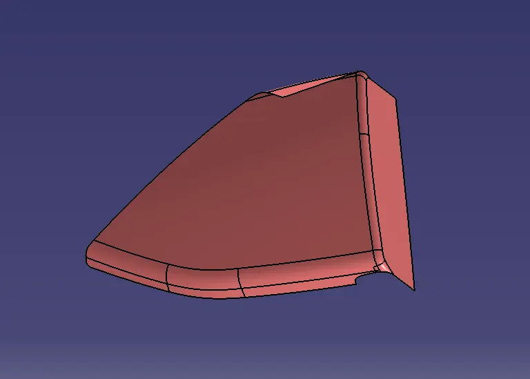
From the given class A surface create the class B Surface by off set the component for 2.5mm out side of the upper map pocket.
After creating the class A surface component we need to create the Tooling axis for the Upper Map Pocket with the proper method.
Tooling Axis Creation for Upper Map Pocket.
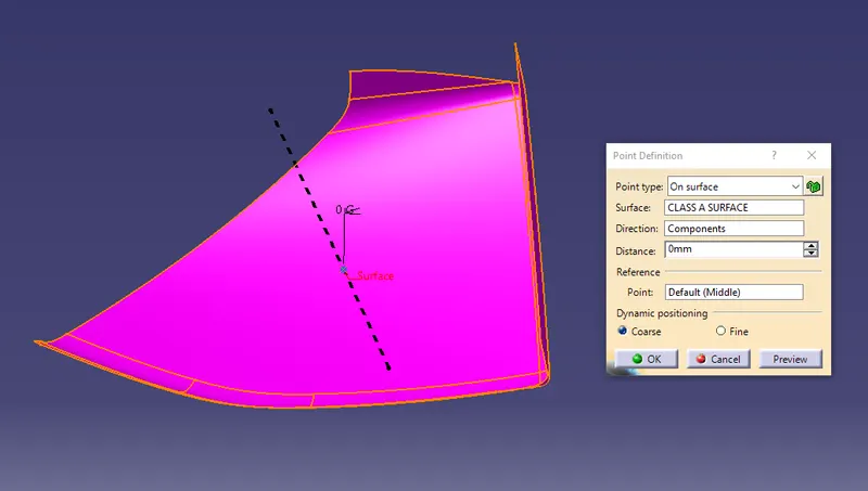
Tooling axis is nothing but direction in which core and cavity open and closes.The design engineers works on it for the class A Surfcace and find out the best possible way of tooling direction keep in mind that all draft direction will be in the tooling axis so that the component can be easily ejected from the mould.
The Main Tooling axis for upper map pocket is created with the following method.
Firstly Extracting Class A surface and consider a point on the surface and create a line on it.
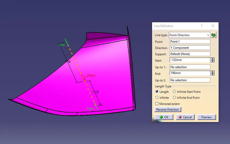
Creating the class B Surface:
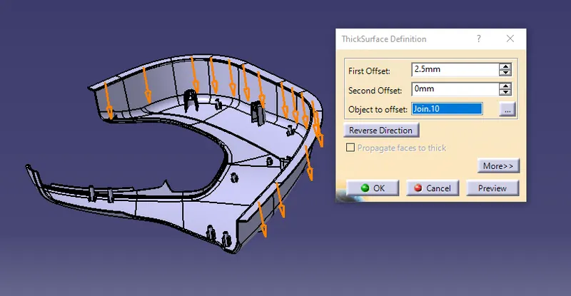
To create a class B surface from the class A Surface offset the class A surface for 2.5mm below of the component.
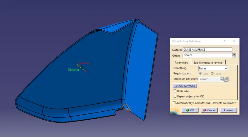
After offset the class surface there will be some patches will be occuring on class B surface we need to work on those patches to make a close surface out of it.
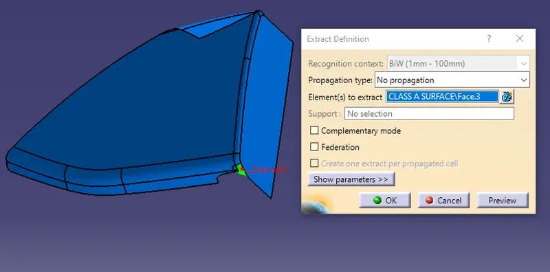
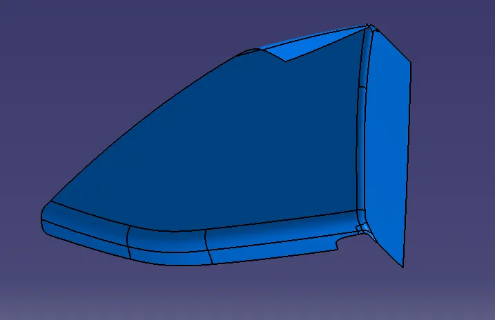
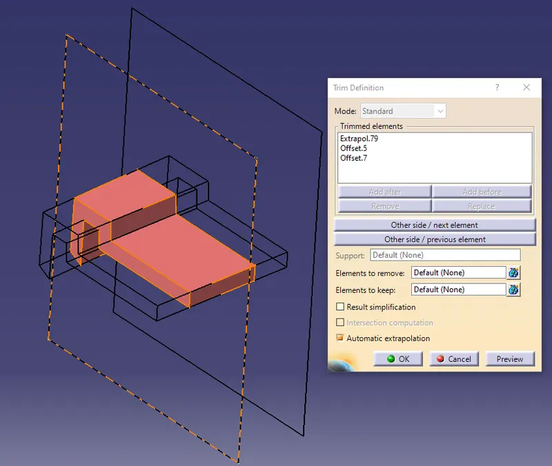
After creating the class B surface its time to create a Class C surface by extracting the class A surface and joined together to form a body of it and finallay trim it with a class B surface to make a solid body out of it.
Creation of Class C surface:
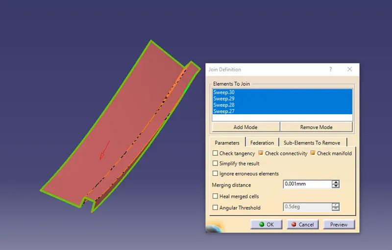
To create a class C surface we need to consider the class A surface and with that by extracting the class A boundaries and make a sweep operations out of it and a make close surface of the class C suraface.
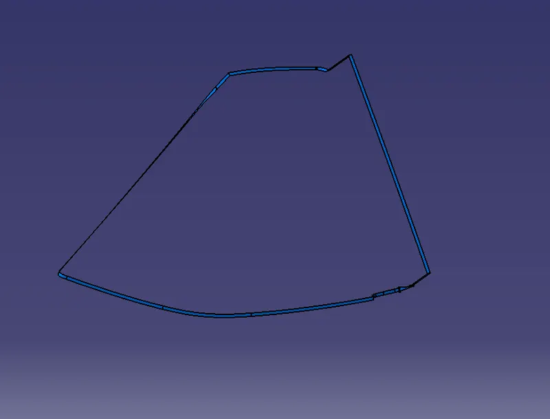
After creating the class C surface we need to add class A + class C together and finally trim it with a class B surface to make closed surface from it.
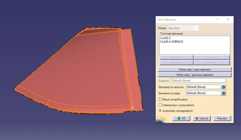
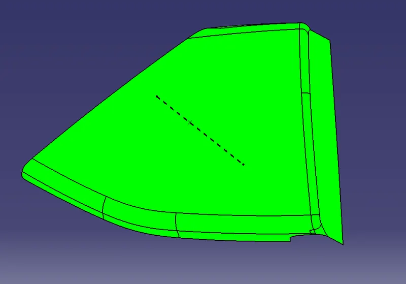
Closed body component of the Class C surface and draft analysis of the component:
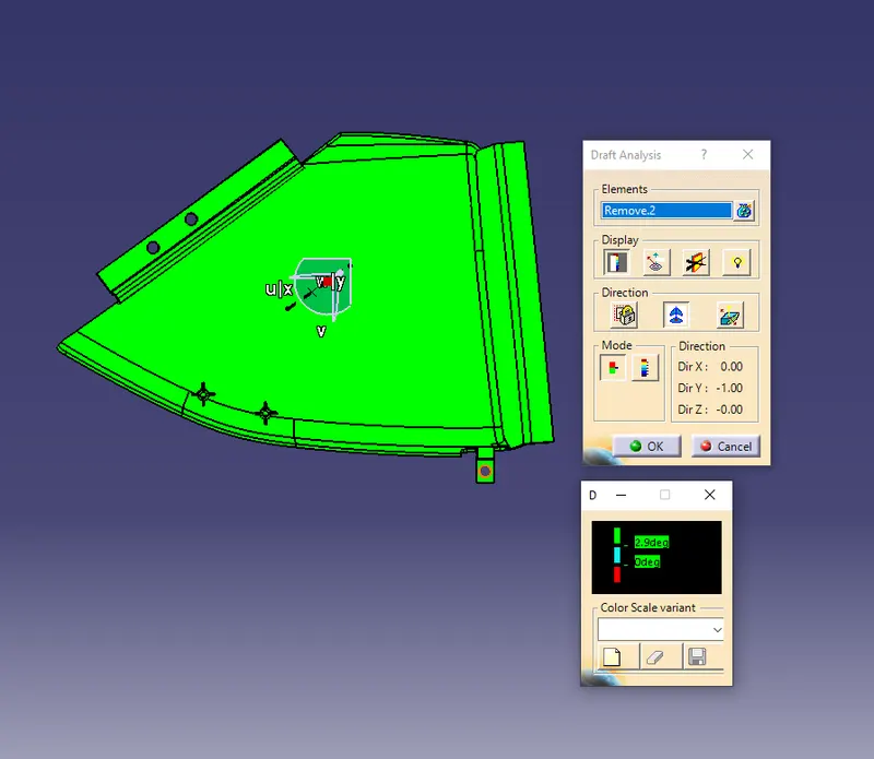
The draft angle for the class C Surface is to be maintained as 3 degree draft angle which is done by the main tooling axis of the component.
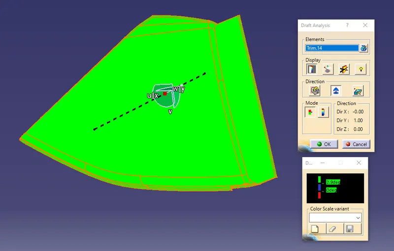
After creating the class C closed surface we need to create the B side features of the upper map pocket and give the draft angle angle as 0.5 degree and make fillet for it.
Creating a mounting flange on upper map pocket by extracting the surfaces and make a closed body out of it.
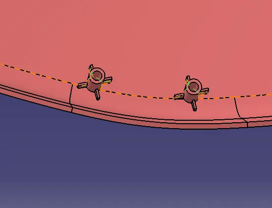
Creating the heat stakes and locators on the upper map pocket and make a closed body out of it and can be drafted for 0.5 degree angle which is easily helpful for ejecting from core and cavity component and is shown in the below figure.
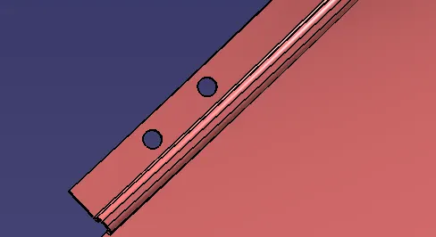
Clearence holes are created on the outer flange of the component so to give a strength to the body component and can be easily be manufactured with the machining operations.
Final closed body component of the upper map pocket is created with all the features containing in it and make a draft analysis for the features and draft can be followed by 3 degree outer body panel and 0.5 degree for the B side features component.
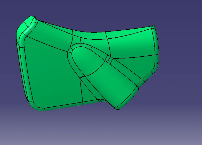
Creating the Class A surface for Lower Map Pocket:
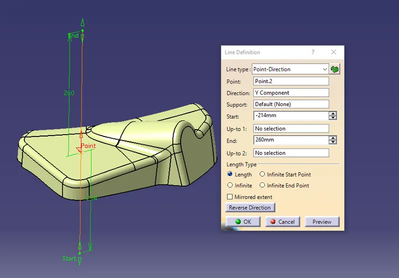
TOOLING AXIS CREATION FOR LOWER MAP POCKET:
The tooling axis for the lower map pocket is created with the follwing method and which should follow the draft direction and can be easily manufactured from tjhe machining operation.
After creating the class A surface component we need to create the class B component by off set the class A for 2.5mm below of it.
Class B surface creation for lower Map Pocket:
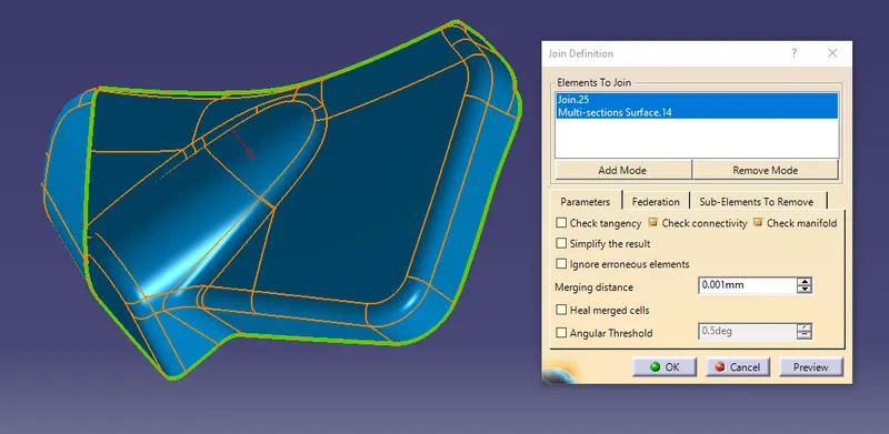
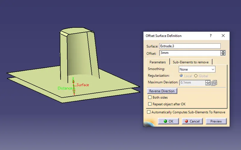
Class B can be created by off set the class A component for 2.5 mm for the outer side of the lower map pocket and there will be small gap araises between the component so that should be filled and make a class B component and it should be shown in the below figure.
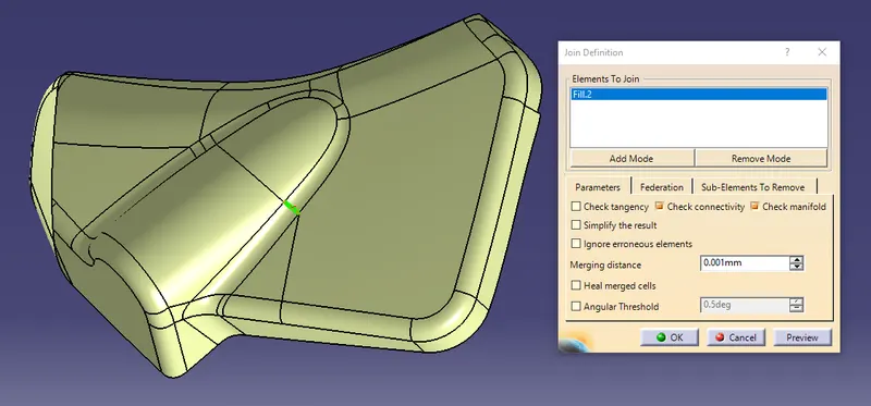
Finally the class B surface can be created according to the design method and will be created with the proper method of it by conidering the extracting, extrapolating the component and make a close surface out of it.
Creation of Class C surface for Lower Map Pocket:
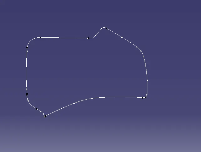
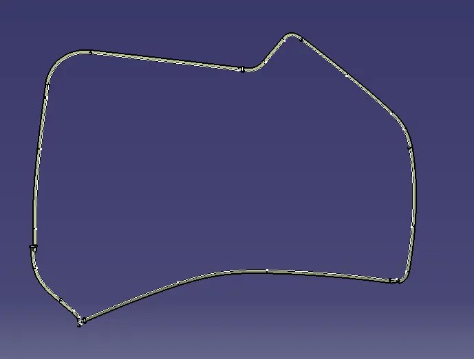
To create a class C surface we need to consider the class A surface and with that by extracting the class A boundaries and make a sweep operations out of it and a make close surface of the class C suraface.
The boundary conditions for the creation of class C surface can be shown in the below figure and after that should not intersect with any other component and can be created according to the sweep operations and all make a close surface out of it.
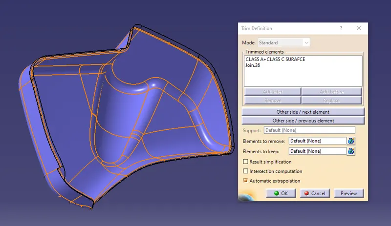
After creating the class c closed surface we need to add class A and class C and trim it with a class B surface so to get a closed from it.
To create a closed surface add both class A and class C surface from it and a closed body from it and is shown in the below figure.
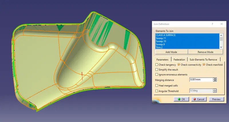
After joining the class A and class C component finally we need to trim both these surfaces with the class B surface to get a final closed body component for the lowr map pocket and it can be shown in the below figure and done with the proper design method.
Finally after creating the class closed component of the lower map pocket component we need to start creating the B side features for the lower map pocket and by providing the draft analysis for the lower map pocket should follow the draft angle for 3 degree for outer panels and 0.5 degree for the B side features and can be ejected and can be manufactured with the machining operations.
Creating the B side Features:
Mounting flange creation on lower map pocket:
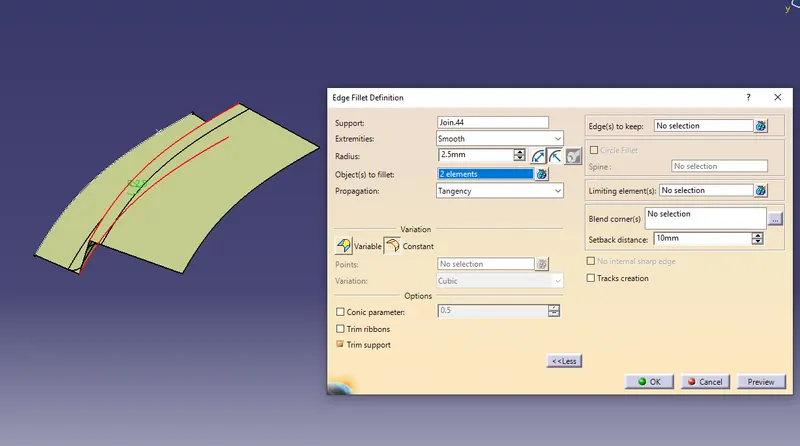
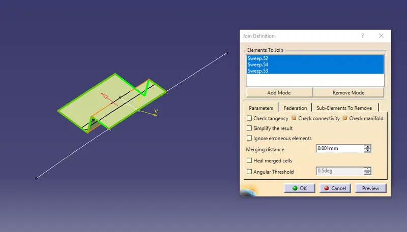
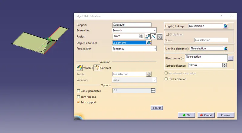
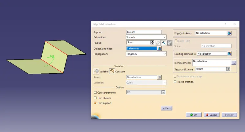
The mounting flange can be made with the extracting the component and can be drawn according to our convenience and make a solid body out of it.
The mounting flanges are created with the proper design method and will be mounted on a lower map pocket and finally attached together to the lower map pocket and draft analysis will perform on the body to manufactured the component.
Creation of Heat stakes on Lower Map Pocket:
Why use of heat stakes for plastic assembly component?
While multiple industrial processes for high quality plastic assembly exist, heat staking continues to earn a significant amount of market share for the sectors. While the industrial products of yesteryear were attached using hardware fasteners, this practice has become obsolete once heat staking technology became the industry standard.
Heat Staking eliminates the need for extra hardware, which can become defective, break, or otherwise suffer from quality control issues. Additionally, hardware fasteners tend to be more expensive and labor intensive than heat staking plastic fastening options.
How heat stakes can be created on plastic assembly component can be shown in the below figure for the referance.
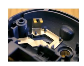
Plastic Assembly with heat staking how does it works can be shown in the below procedure?
Heat staking technology is quite simple in concept. Whenever two or more components need to be attached to one another, and at least one is made of a thermoplastic, a combination of heat and pressure can be used to reform the plastic to the many shapes or profiles to retain or join the parts together.
This creates a solid, hardware-free bond that uses the plastic’s inherent strength to keep the finished assembly together.
The main advantage to heat staking, when compared to fastener-based technologies, is that manufacturers can perform all heat staking in one machine cycle and motion versus individual motions required for each fastener. A secondary benefit is that the manufacturers do not need to change the base material – it can remain “AS-IS” while the plastic is heat staked to conform to its final dimensions.
Unlike ultrasonic plastic assembly, which uses high-frequency vibrations to generate the heat necessary to bond plastic components to one another, heat staking is safe to use with a broad range of electronics and produces a higher pull strength versus the ultrasonic technique. Ultrasonic vibrations have been known to effect or damage sensitive electronic components and cause cold solder joints or stress cracks in the printed circuit boards.
Heat staking technology, on the other hand, creates almost no mechanical stress because it operates through a precise control and application of the temperature and pressure to cause the reforming of the plastic that it makes contact with. Even glass-filled plastics can be reliably joined using this method of heat staking – which is not the case for cold staking or other techniques.
The fact that heating is completely localized within a small area means that electronics are safe from damage. Thermal Press’ plastic assembly machines can operate very precisely within the small process temperature windows, as demanded by the most delicate and the most difficult thermoplastics used in todays’ high-end medical, automotive, telecom and consumer products.
Draft analysis on the Lower Map Pocket component is shown in the below diagram:
Applications of Heat Stakes in Plastic Component:
- In the automotive industry, in electronics production, but also in medical technology, the highest quality and cleanliness requirements must be met.
- The products are exposed to high loads over their service life and must reliably fulfill their function. This requires the highest possible accuracy and reproducibility during production.
- In addition, the best possible process result is sought in the shortest possible time.
- Processes must therefore be developed which, on the one hand, fullfill the individual properties of the materials and, on the other hand, generate low costs. This is where heat staking is increasingly used.
- The range of products for which the heat staking process is used is extensive.
- Typical applications are the permanent fixing of printed circuit boards in and on housings or of covers with housings, the joining of busbars, insulators, cooling plates or microelectronic components.
- From control units in vehicles to sensors for driver assistance systems, locking systems, vehicle interior trim, in front lights and rear lights, in the engine compartment, in media guides, in oil, and in battery and electric motor production - heat staking processes are used in a wide variety of ways in the automotive industry.
- Whether brown or white goods, hot rivet technology from bdtronic is even used in sanitary engineering.
- The applications of this cost-efficient joining technology are diverse.
- Sometimes it is used to pre-fix a component, such as a bus bar or a stamped grid, in the production flow prior to potting, soldering, welding or wire bonding.
Draft Analysis concept on plastic component:
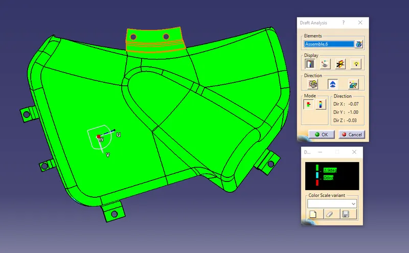
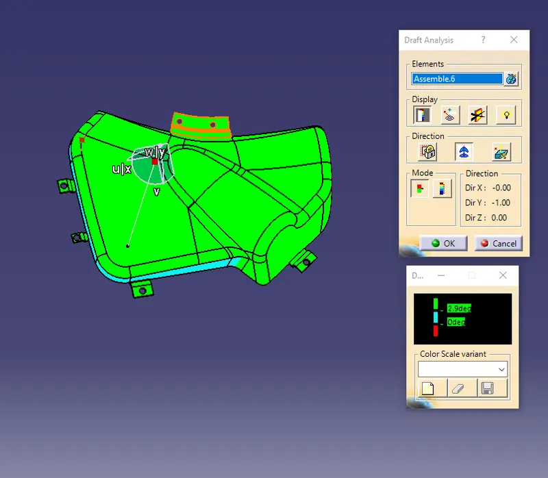
This type of analysis is performed based on the type of color ranges to identify the zones on analyzed where the deviation from the draft direction at any point, corresponding to the specified values.
The draft analysis button in CATIA V5 will help you quickly gather the draft angle component on the multiple surfaces without the need of tedicious manual measurments.
Final closed body component of thelower map pocket is created with all the features containing in it and make a draft anaylysis for the features and draft can be followed by 3 degree outer body panel and 0.5 degree for the B side features component.
Creation of class A Surface for Lower Substrate:
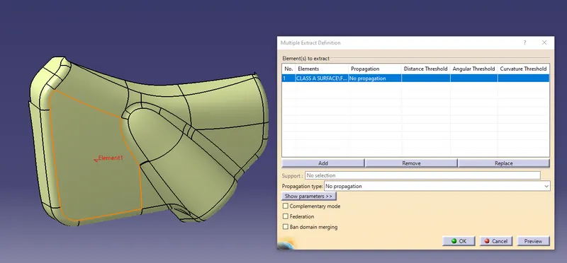
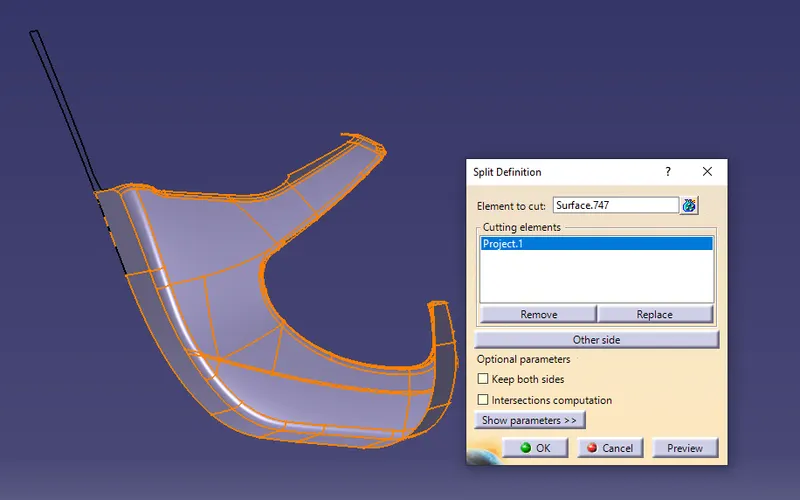
The class A surafce can be extracted from the given surface and make a proper closed surface of it and the extended surface can be removed by the multiple operations.
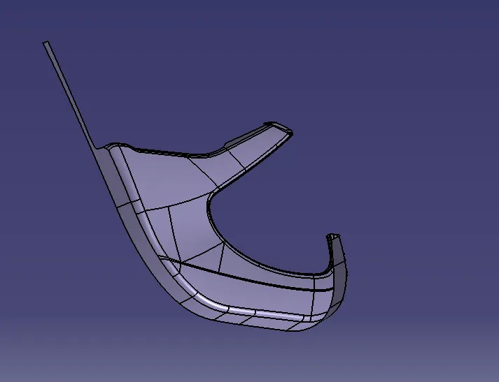
The extended pib on the lower substrate can be removed with the help of multiple operations and can be made a proper class A surface of it.
The line can be created on the lower pib on the substrate so to get a proper class A surface from it which can be shown in the below figure.
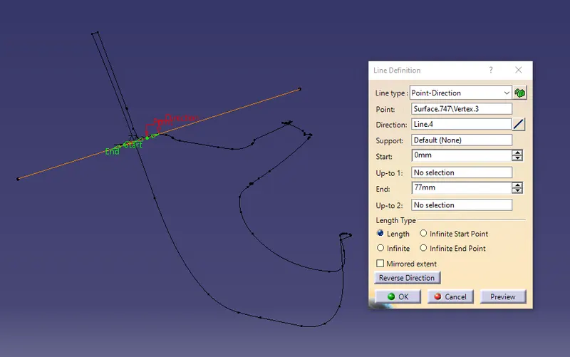
To get the proper shape on the lower substrate of class A component perform the operations on it and get proper shape of class A and which is shown in the below figure.
Creating the Tooling Axis for the Lower Substrate is explained below:
The main tooling axis for lower substrate can be created from creating the point and line on the lower substrate which should follows draft analysis of the component with 3 degree drfat angle which cleares the tooling direction along with it.
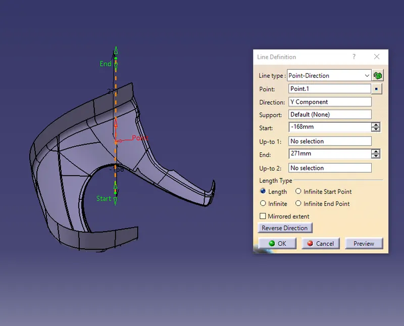
Creation of Side core tooling axis for Lower substrate:
The side core tooling axis for lower substrate can be created from creating the point and line on the lower substrate which should follows draft analysis of the component with 0.5 draft angle and can be applicable for the draft component to follow the B side Features.
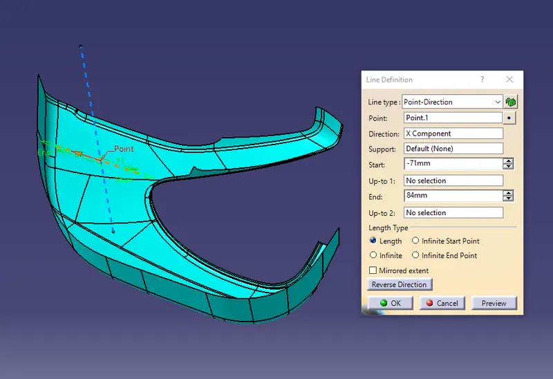
Creation of Class B surface for Lower Substrate is as follows:
Class B can be created by off set the class A component for 2.5 mm for the outer side of the lower substrate and there will be small gap arraises between the component so that should be filled and make a class B component and it should be shown in the below figure.
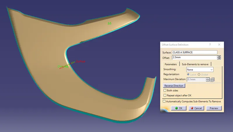
After creating the B surface component for the lower substrate just extract the boundary from it and make a class C component.
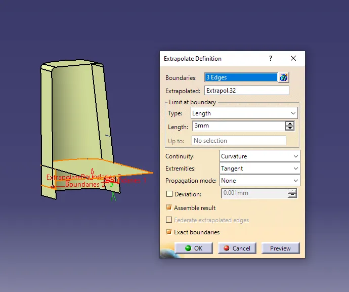
Just extrapolate the extracted component of the B surface for the required dimensions to cut it wih the class A and class C component to get a closed body out of it.
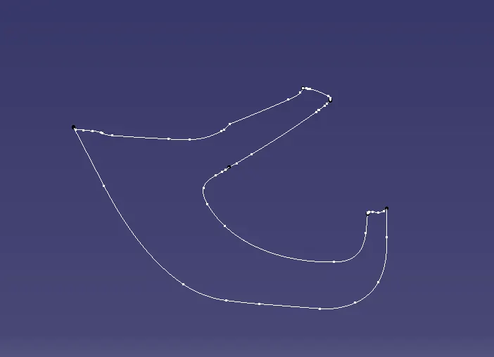
The final class B surface can be created with extrapolating the component by taking the boundary conditions from it for a limited value of the B surface component.
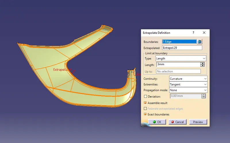
Creation of Class C surface for Lower substrate:
To create a class C surface we need to consider the class A surface and with that by extracting the class A boundaries and make a sweep operations out of it and a make close surface of the class C suraface.
The boundary conditions for the creation of class C surface can be shown in the below figure and after that should not intersect with any other component and can be created according to the sweep operations and all make a close surface out of it.
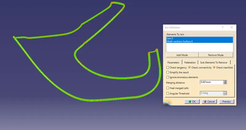
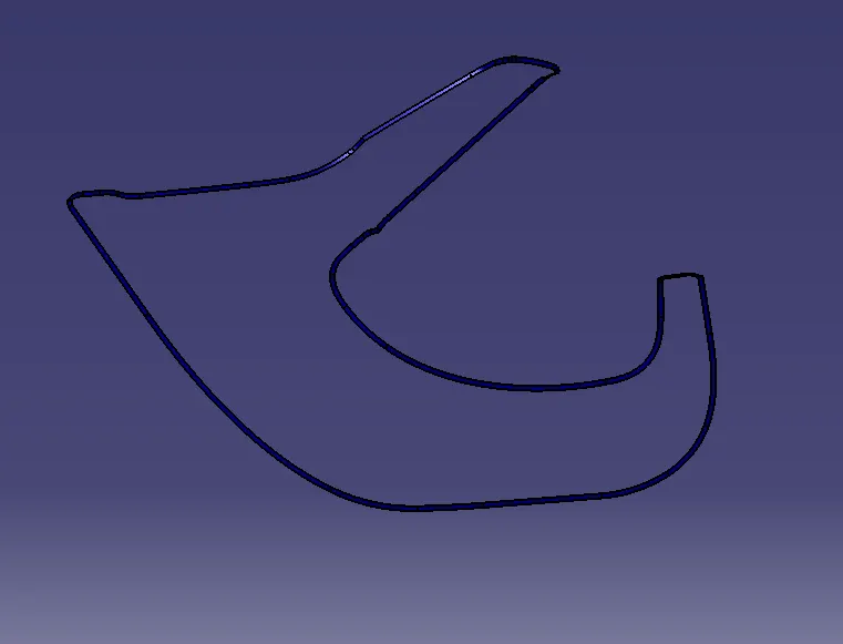
The joining of class A and class C component can be mentioned in the below figures so to get trimming it with the class B surface and finally we will be able to get the closed body component from it.
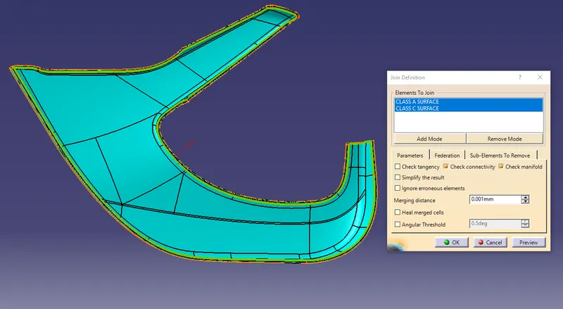
The final trim for the creation of lower substrate canbe made with the help of combining together of class A and class C with class C can be shown in the below figure.
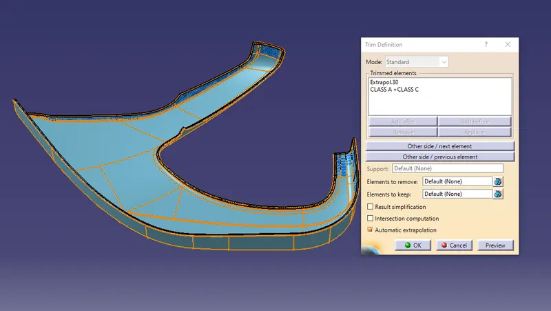
After creating the final trims for the lower substrate component we are gonna create the B side Features on this lower substrate like, FLANGES, LOCATORS, HEAT STAKES, DOG HOUSE Etc..
Creation of Flanges on lower substrate:
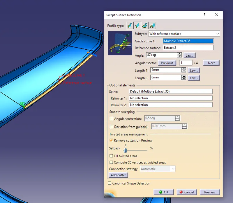
Creating the heat stakes on the lower substrate:
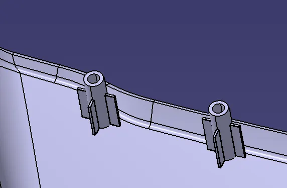
By extracting the components of final trimming opertaions ob lower substrate we were able to create the hest stakes on it and make a sketch of it and do the part design operations like padding or shaft to make a closed component from it.
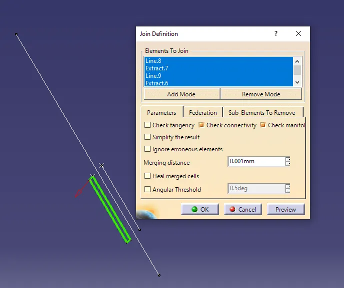
We need to make a closed body component for the creation of hest stakes on the lower substrate and which can be done by using the shaft tool from the part design workbench and shown in tge below figure.
Creating the Locators on the lower substrate:\

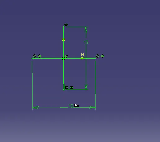
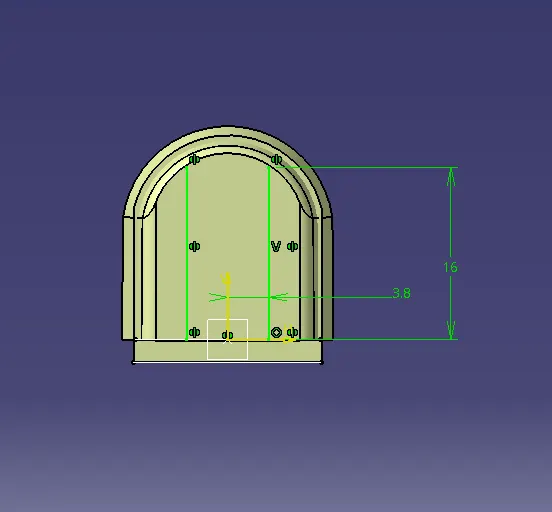
The locators can be created by the scrach with the proper dimensioning method and dimensions are made along with the proper method and its sketch is mentioned in the below figure.
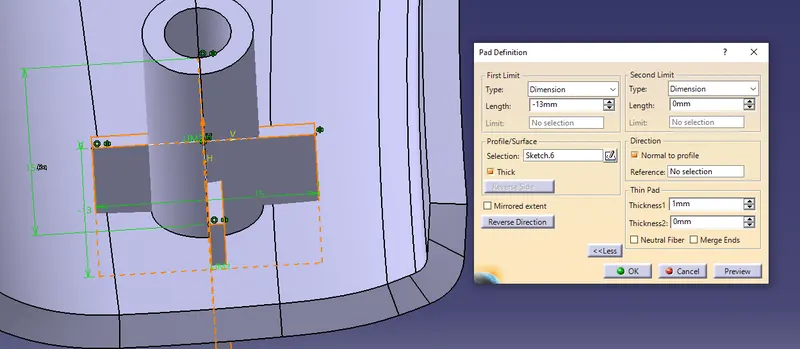
For the locators we will do the padding operations with the proper thickning method applying on it and make the neutral fibre component so that it should not come outside of the heat stakes.
The body thickning of the locators can be shown in the below figure:
Creation of Dog House on Lower Substrate is with the proper method:
Design considerations for creating the Dog House on a lower substrate is as follows:
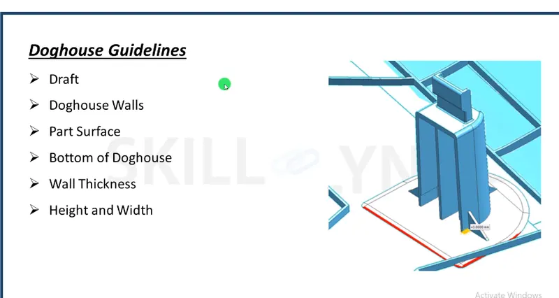
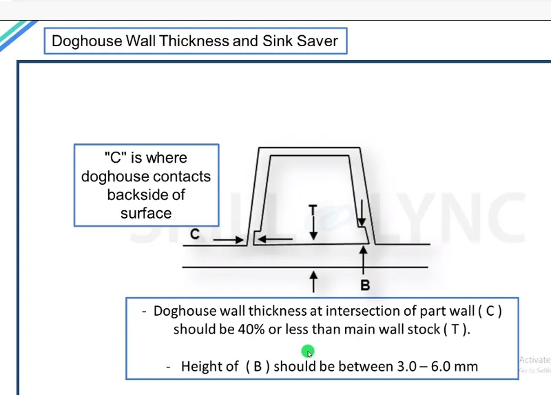
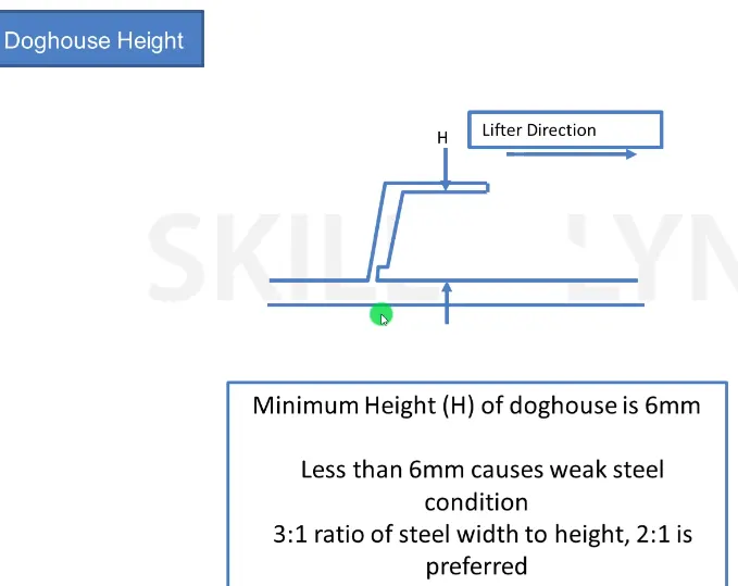
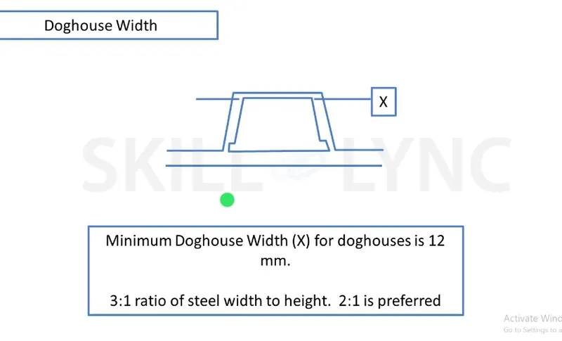
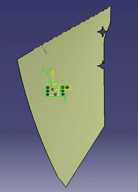
By off set the dog house according to the required dimensions we were able to create the proper dog house design on lower substrate.
The undercut for the dog house can be made with the proper dimensioning method and can be design according to the design considerations and it is shown in the below figures.
By creating the undercut inside the dog house component we should create the support for the dog house so that the push pins can be located on the upper part of the dog house design and can be made with the proper design method.
The slot creation on the dog house is made for mounting the push pin on the dog house and can be placed on the closed body component and is shown in below figures.
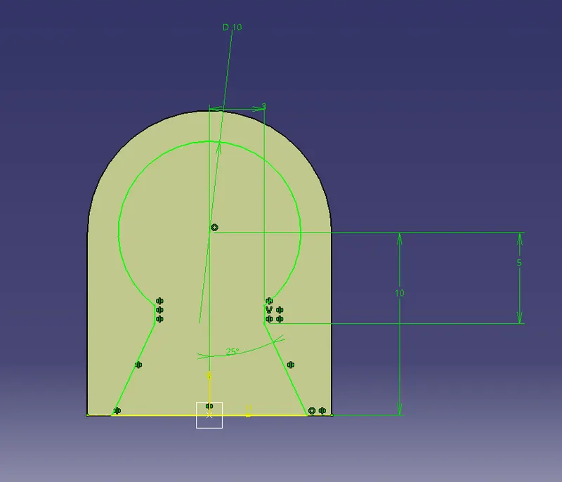
The closed body component of the dog house is created and can be shown in the below diagrams which is made with the proper dimensioning method.
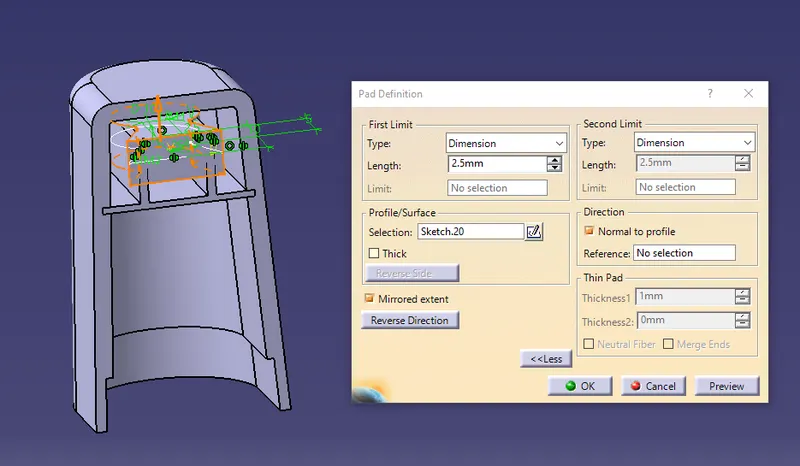
Creation of Outer Flange on Lower Substrate can be made and is shown in the below figures and fillet can applied to the inner and outer body surface and can be provide the edge fillet for inner diameter of 2.5mm and outer face diameter of 5mm to get the closed body component.
Application of Dog House in plastic Component:
- Dog house is an engineering feature used in plastic trim design. Dog houses are used as supporting feature.
- Dog houses are subjected to draft analysis to prevent breakage of the component during ejection from mould cavity.
- Dog house and other engineering components are built on B-surface.
- They provide enough room for the dog to fully stand up, move around and even have access to dog food and water.
- They are elevated above the ground to provide ventilation during hot weather and to avoid the floor from getting too cold during winter.
Finally after creating the closed body of lower substrate component we will be able to perform the draft analysis for the creating component in which outer body of the lower substrate should follow the draft angle of 3 degree draft angle and B side features can be drafted with the help of side core tooling axis which follows the 0.5 degree draft angle and can be easily manufacturable after the machining operations wgich is conducted by following the color code component. In which green color indicates the draft is perfectly happening for the part and blue color indicates the draft angel is under its method and red color indicates that the class A component is not proper and we should inform to the class A desinger tpo provide the proper class A surface.
Draft analysis for Lower Substrate on closed body component:
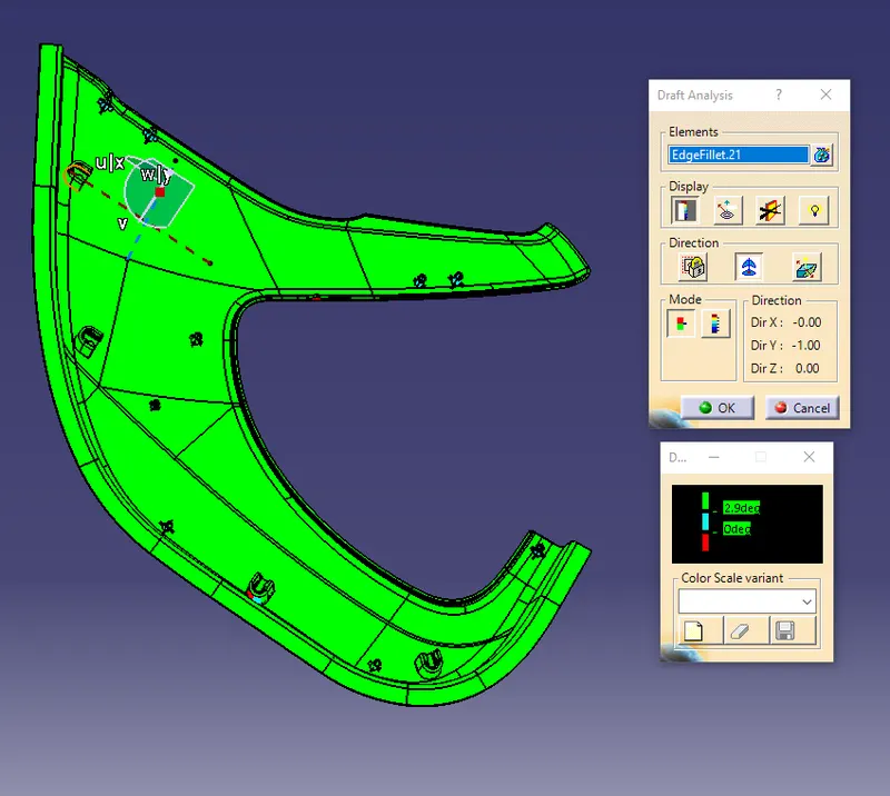
Draft analysis on lower substrate Dog house component:
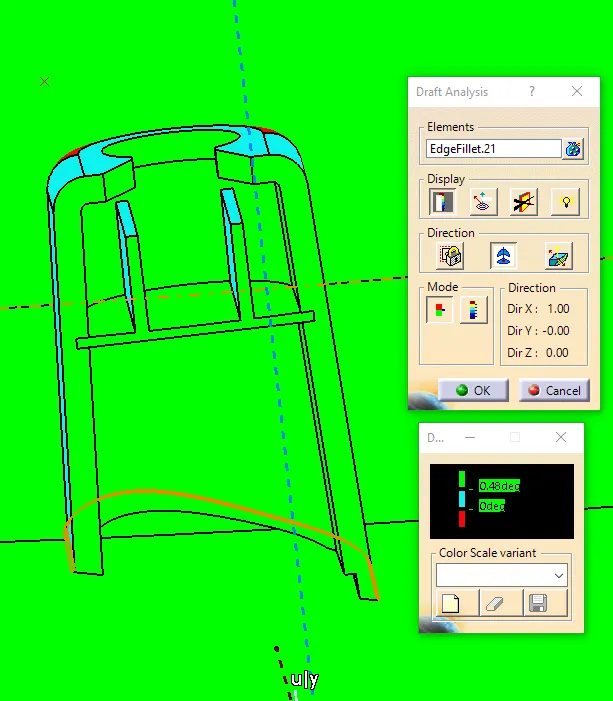
Draft analysis on lower substrate for heat stake component:
The draft ananlysis for the heat stake on lower substrate is cleared with the side core tooling axis and can be easily be manufactured with the machining opertaions and core and cavtiy can be easily ejected from moulding operations.
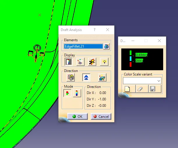
The push pins are loacted on the lower substrate of dog house component so that it can be easily fix on the other door panel component to provide the stregthning to the part.
PUSH PINS DESIGN:
Applications of Push Pins:
- ✎ These rivet fasteners are made of nylon material.
- ✎ Suitable for car use.
- ✎ Cars good accessory, commonly used for fitting side skirts, bumpers and other trim.
- ✎ Replaces factory push pin rivets on many brands of vehicles.
How Push Pins Are Placed On the Dog House of Lower Substrate:
The pushpins closed body component are gonna placed with the help of assembly work bench by constraining the axis to axis combination of the Dog house and Push pin.
Firstly we need to constrained the axis of pushpin and Dog house and manupulations are constrained and placed on a specific ares and after that we need to constrained the surface to surface contact of pushpin and dog house to be placed with each other.

Location of Push pins on a Lower substrate of Dog House:
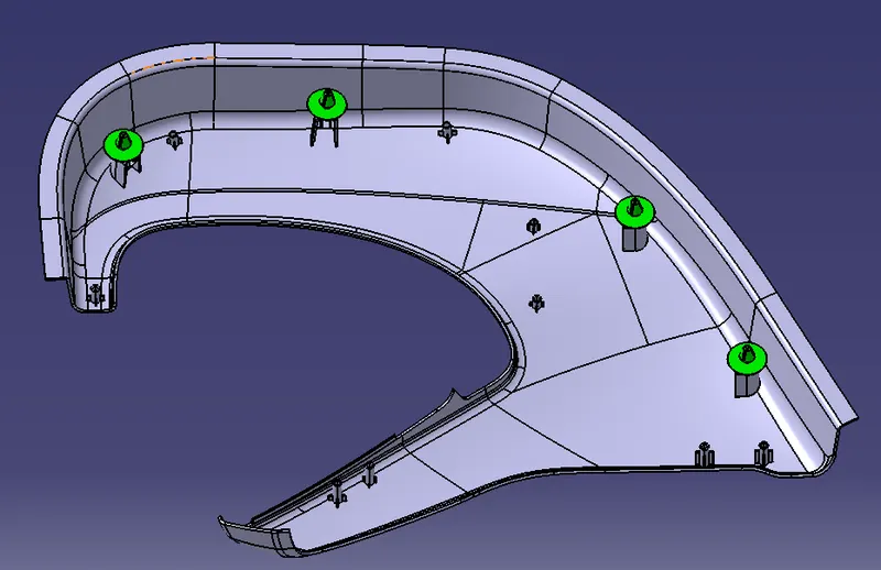
Creation of Class A surface for Door Arm Rest and Switch Bezal component:
Class A creation for Door Arm Rest:
The class A surafce can be extracted from the given surface and make a proper closed surface of it and the extended surface can be removed by the multiple operations.
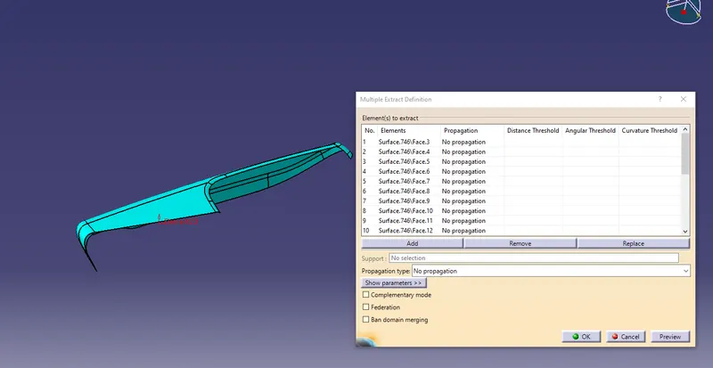
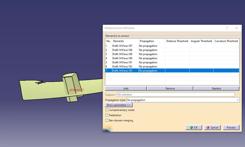
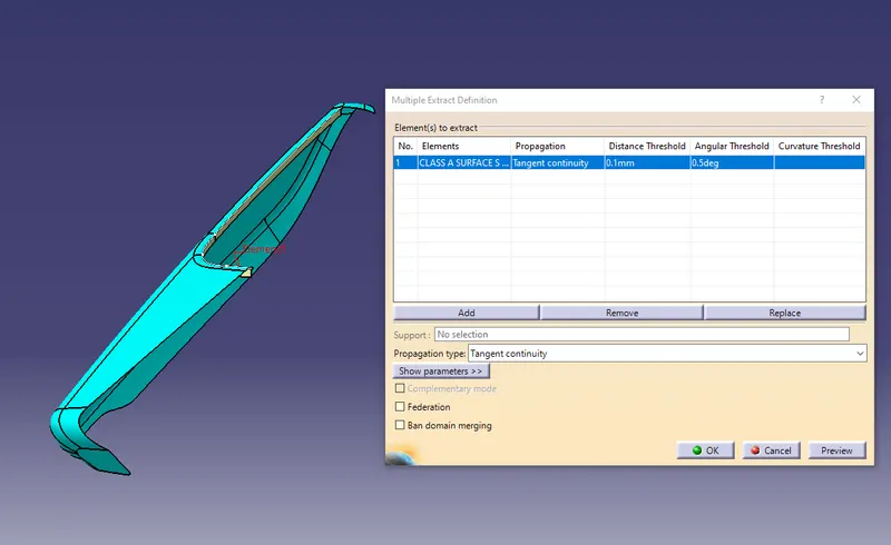
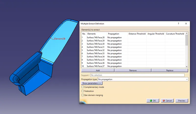
The extracted class A surface can be done by using the multiple extract operations so that it can be separated from the switch bezal component and sweep can be done to get the proper design of the component.
Creation of Tooling Axis for the Door Arm rest component:
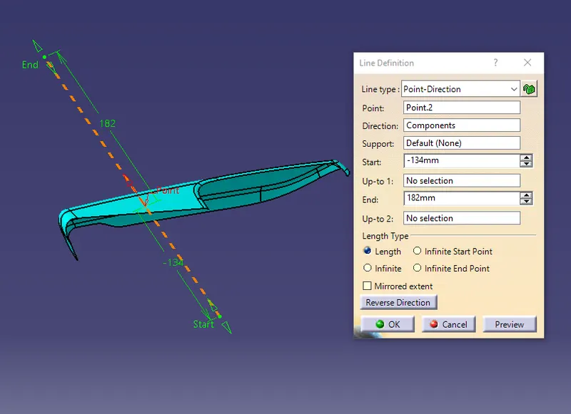
The main tooling axis for the door arm rest can be created with the compass method by locking the tooling direction of the component with the proper method followed by the design considerations from it.
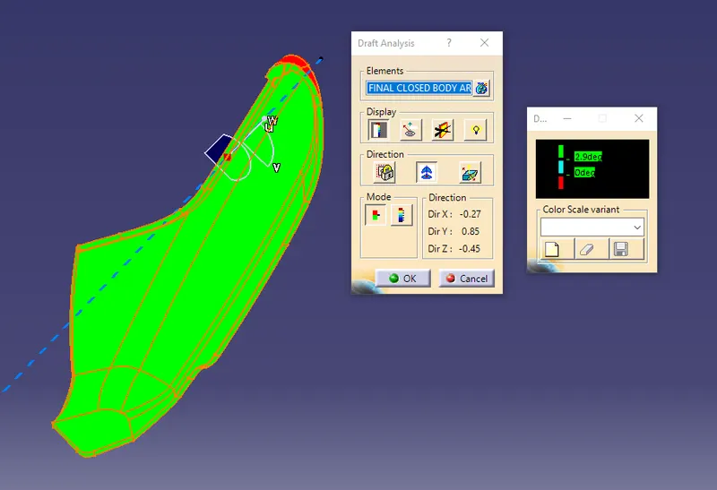
The main tooling axis for door arm rest is created by the following method and shown in the below figure which should followed by the draft angle component and clears the draft analysis of the door arm rest outer body component and can be easily Ejected from the Core and Cavity design consideraions.
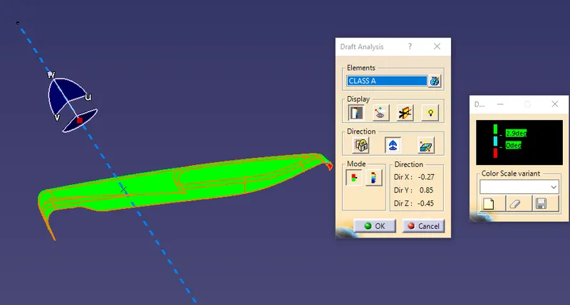
Draft analysis on class A component which clears the draft angle projection:
Improvement of class A component:

Creation of class B surface on Door arm Rest:
Class B can be created by off set the class A component for 2.5 mm for the outer side of the door arm rest and there will be small gap arraises between the component so that should be filled and make a class B component and it should be shown in the below figure.
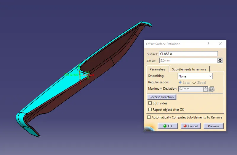
By extrapolating the class B Surface for the required dimensions so that it can be trim it with a class A and class C component to give a proper closed surface of the door arm rest.
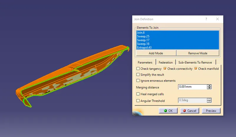
Creation of Class C surface for Door Arm Rest:
To create a class C surface we need to consider the class A surface and with that by extracting the class A boundaries and make a sweep operations out of it and a make close surface of the class C suraface.
The boundary conditions for the creation of class C surface can be shown in the below figure and after that should not intersect with any other component and can be created according to the sweep operations and all make a close surface out of it.
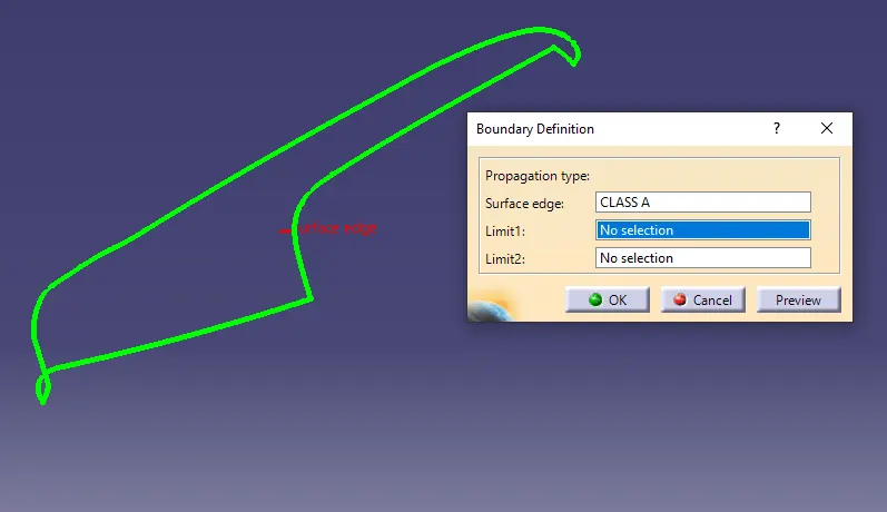
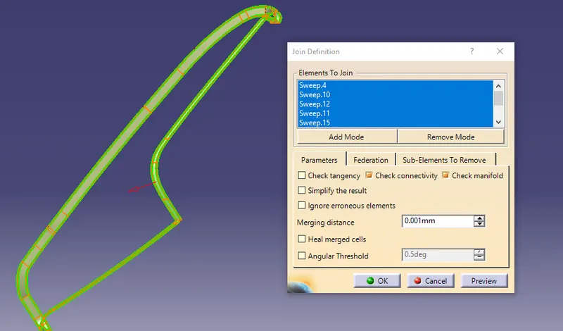
The combination of class A and class C can be made and it can be trimmed with a class B surface so that it gets trimmed off and provides a closed body component from it.
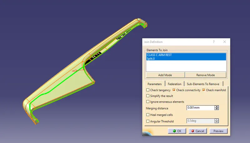
After joining the class A and class C component together we need to trim them both with the class B surface to get a closed body component from it by doing the proper method of trimming operations on it.
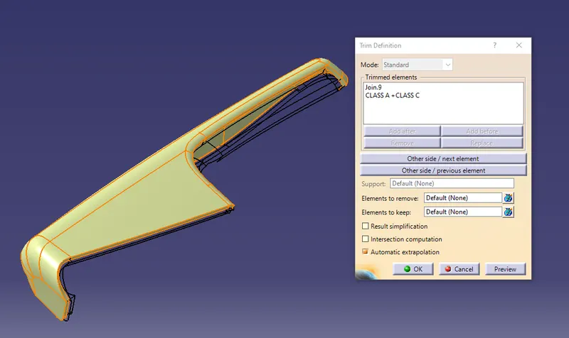
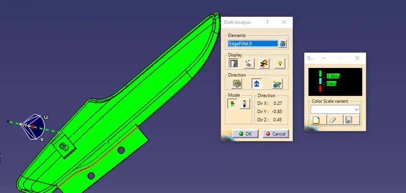
The draft analysis for the closed body component can be done with the main tooling axis for the door arm rest component and which follows the draft angle and clears the draft of tooling direction which is shown in the below figure.
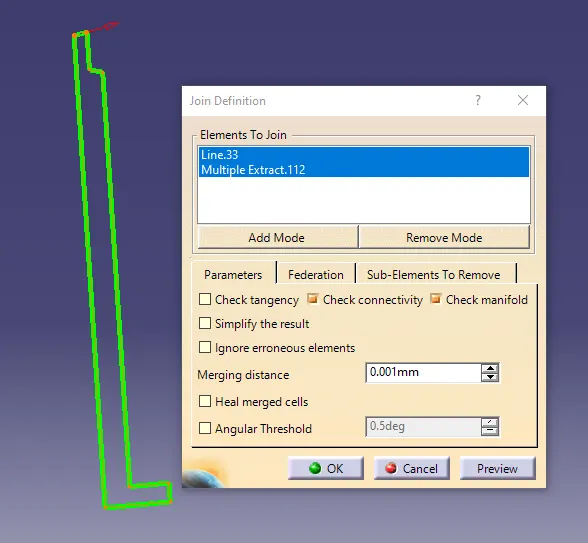
Just after creating the closed body component for the door arm rest component we are now able to create the B side Features on the Door Arm Rest like as Dog House, Heat stakes and Mounting Flanges on it and make solid body of them.
Creation of Dog house component which follows the Master sections and can be extracted from the given data and make a sketch out of it and make a solid body for the creation part.
The closed body for th Dog House of arm rest is created by the following method and made a closed body component from it.
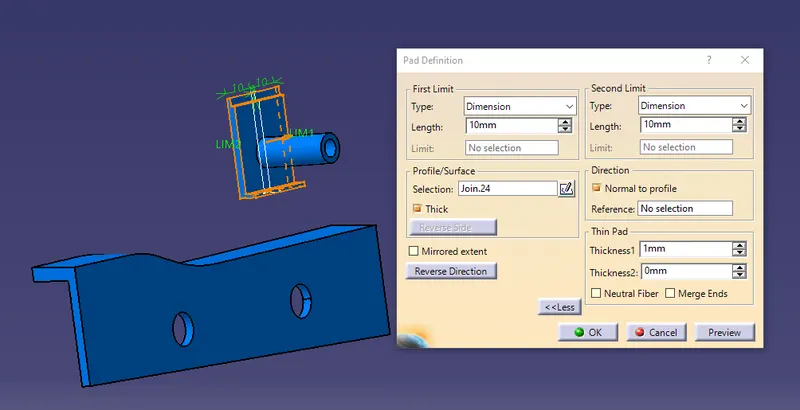
The Mounting Flange on the door arm rest component can be created and it is shown in the below figure.
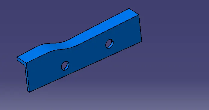
After joining all the parts together for the door arm rest component we can make solid body out it and we will perform the draft analysis for the created door arm rest component wgich follows the draft angle and cleares the draft angle and can be easily manufacturable by doing the machining operations.
Closed Body For Door Arm Rest component:
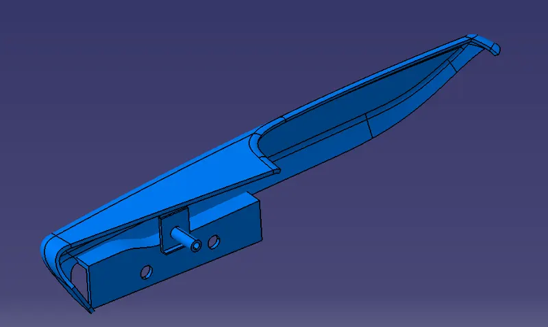
Draft analysis for the Door arm Rest:
Creation of class A surface for Switch bezal component:
The class A surafce can be extracted from the given surface and make a proper closed surface of it and the extended surface can be removed by the multiple operations.
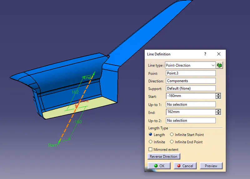
Creation of Tooling axis for Switch Bezal:
The main tooling axis for the door arm rest can be created with the compass method by locking the tooling direction of the component with the proper method followed by the design considerations from it.
The main tooling axis for switch bezal is created by the following method and shown in the below figure which should followed by the draft angle component and clears the draft analysis of the switch bezal outer body component and can be easily ejected from the core and cavity design consideraions.
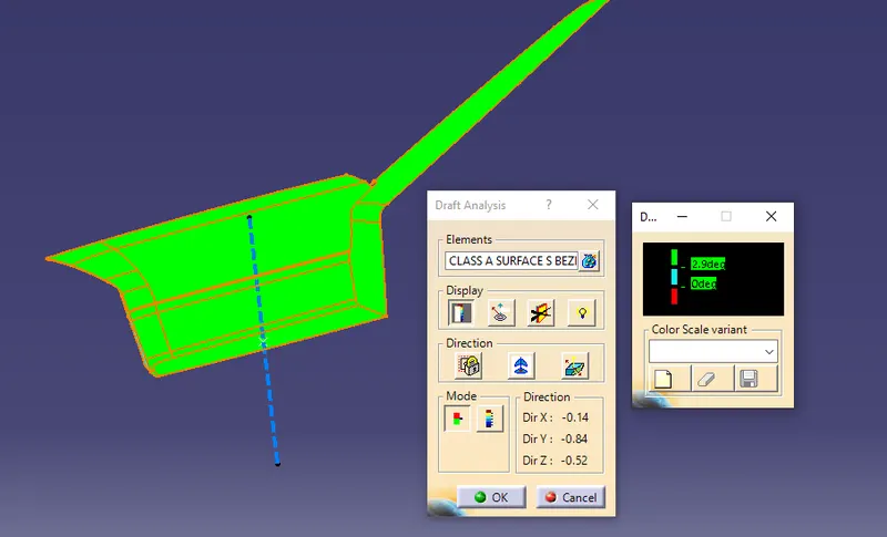
Draft analysis on class A for Switch Bezal:
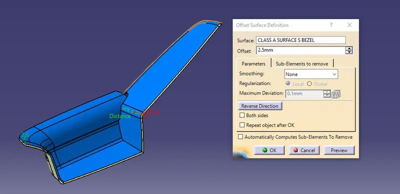
Creation of class B surface for switch bezal component:
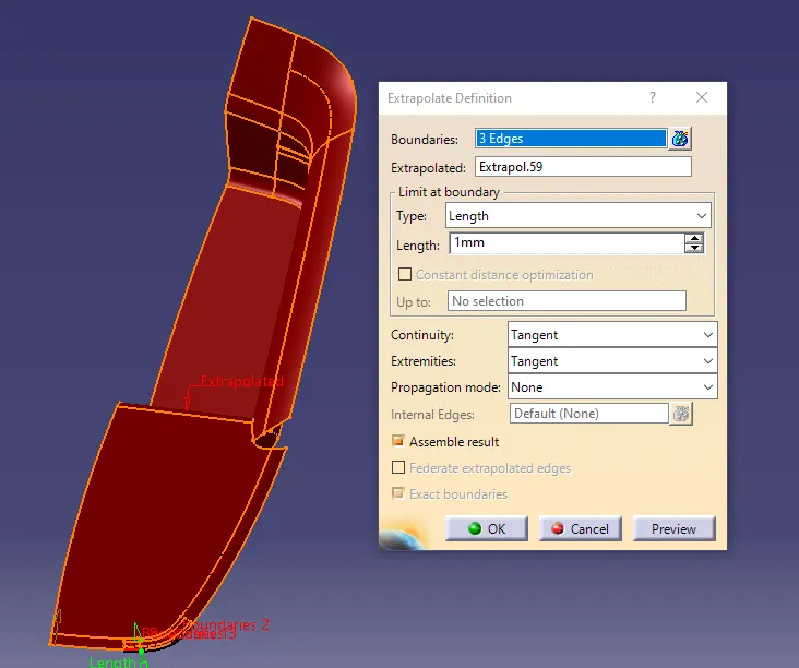
Class B can be created by off set the class A component for 2.5 mm for the outer side of the door arm rest and there will be small gap arraises between the component so that should be filled and make a class B component and it should be shown in the below figure.
The local patch will be araised on the class B surface after off set it for 2.5mm below of it and we can be filled with a multisection solid component.
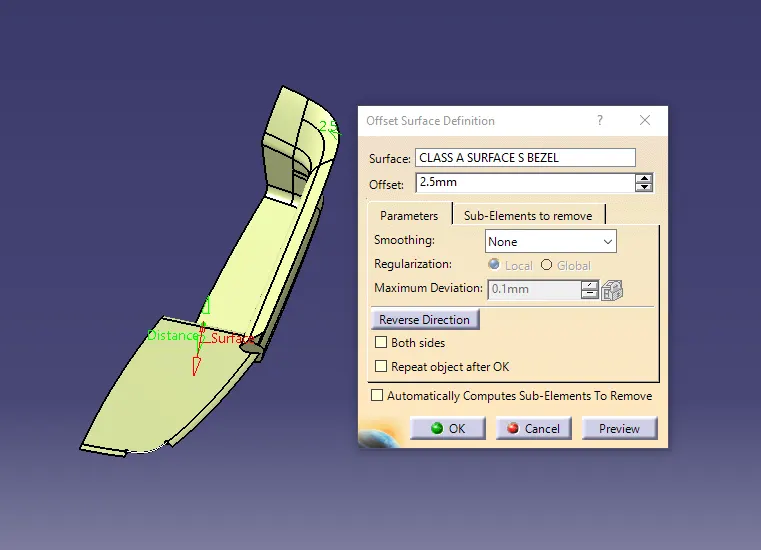
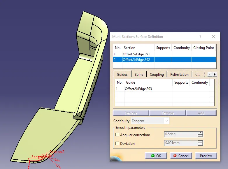
After closing the local patch which is araised on the class B surface we will get the final class B surface from the joining and all.
Creation of class C surface on Switch Bezal component:
To create a class C surface we need to consider the class A surface and with that by extracting the class A boundaries and make a sweep operations out of it and a make close surface of the class C suraface.
The boundary conditions for the creation of class C surface can be shown in the below figure and after that should not intersect with any other component and can be created according to the sweep operations and all make a close surface out of it.
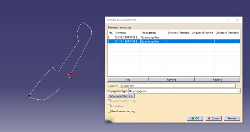
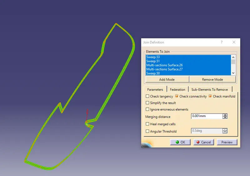
After getting the closed surface of class C component we need to add class A and class C to get trim with the class B surface from which we were able to get the closed body component of it and draft analysis can be done from it and which allows the tooling direction in which the part can be created or manufactured from the machining operation.
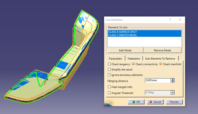
The final trim on switch bezal can be done by joining of class A and class C which is going to trim with the class B surface to get a closed body component from it and it is as shown in the below figure.
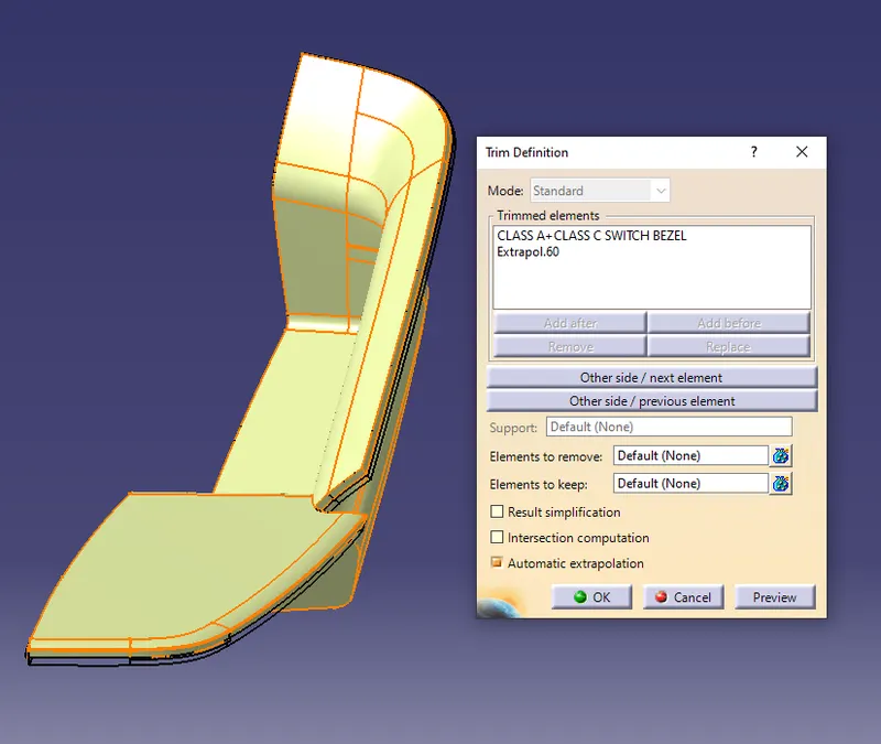
Now its time to create the B side features on the switch bezal component like as mounting flange, Ribs Etc....
Creation of Ribs on switch Bezal component:
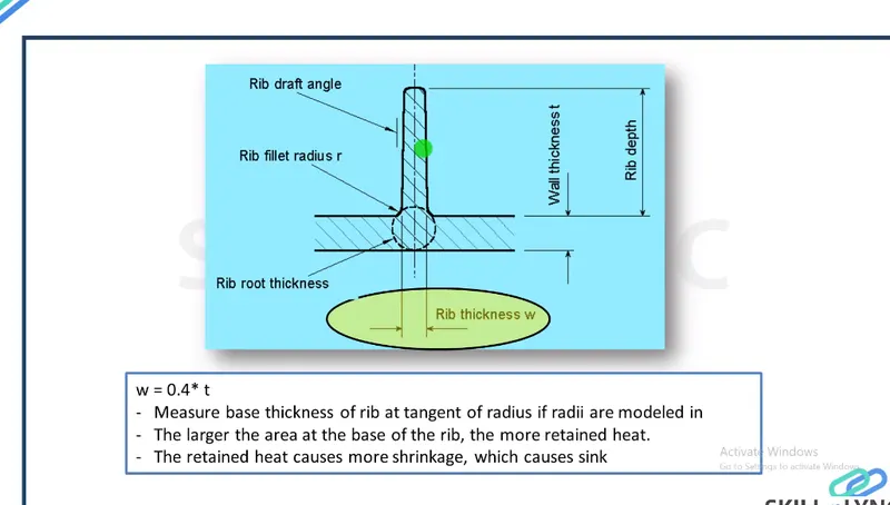
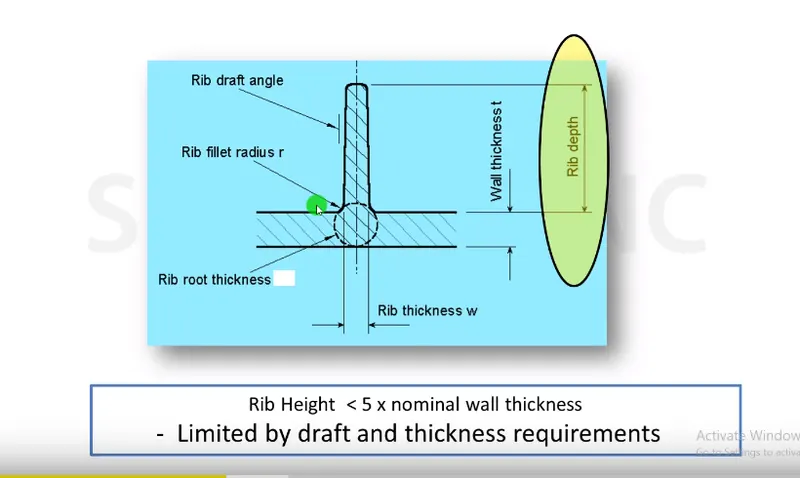
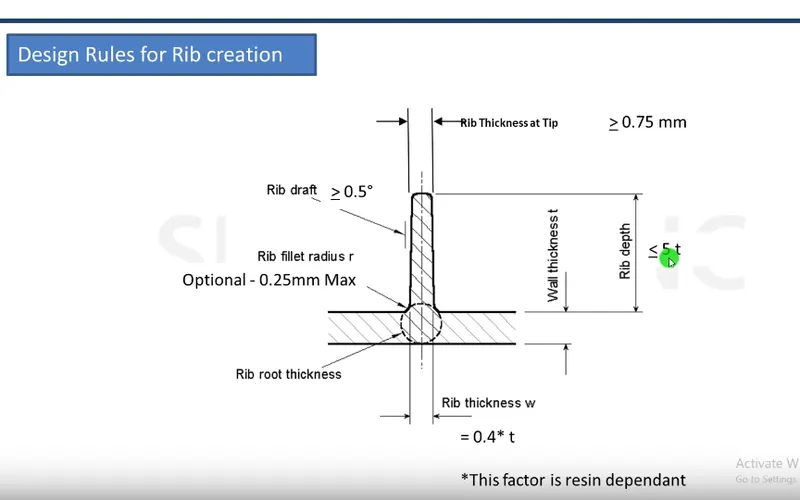
The ribs can be created on the lower part of the switch bezal component so that it provides the strength to the switch bezal and can be able to provide the rigidity for connecting with the lower part of the switch bezal component and its design methodology is shown in the below figure.
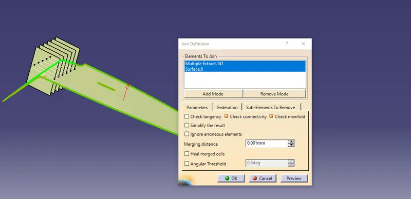
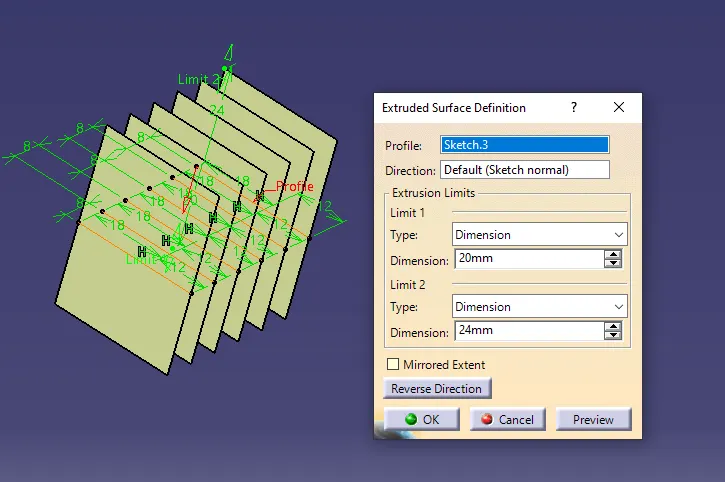
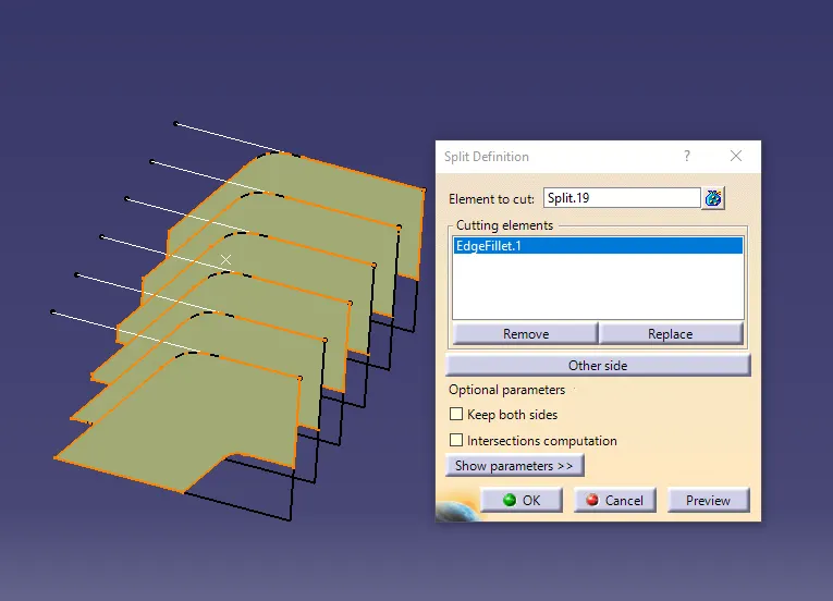
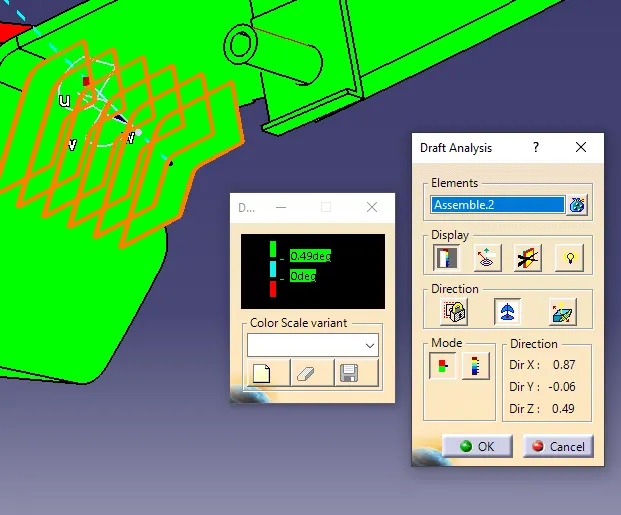
Finally the Draft analysis for the ribs creation on the switch bezal component can be done with a lifter axis of draft angle 0.49 draft and which follows the draft direction and is shown in the below figures.
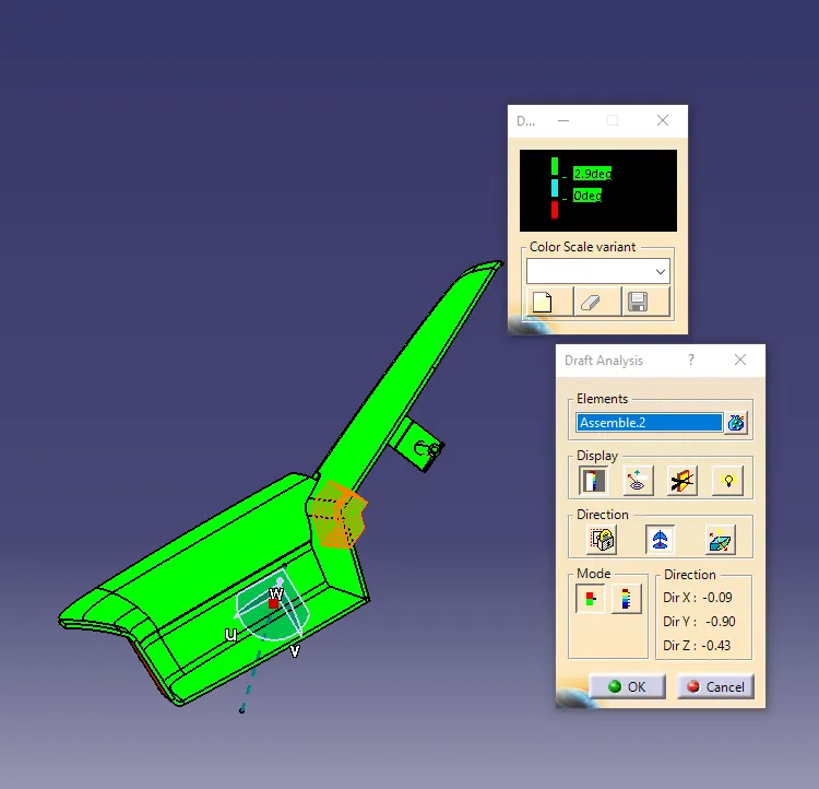
On the closed body component of switch bezal the draft analysis is conducted and it is clearing the draft angle of 3 degree and can be easily manufacturable with the machining operation and its draft is shown in the below figure.
The Final Multisection Views of Door Trim Creation is shown In The Below Figure: