Week 8 - Challenge 2 - Base Bracket Design
The draft analysis of a tooling axis can be done by using the base bracket component is by following the plane definition option.
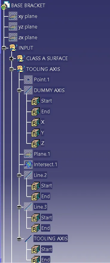
With the selection of the midpoint of the tooling axis of a base bracket component we can create a tooling axis of a solid part of the body.
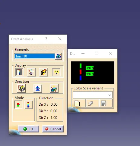
The minimum draft angle maintaining between the two class A surfaces should be around about 3 degree to obatined the exact location of the component.
By creating a class A surfaces by maintaining the distance between the two components which is more efficient.
We need to create a class A surfaces and class B surfaces in between the two components which are more effficient for the solid model components.
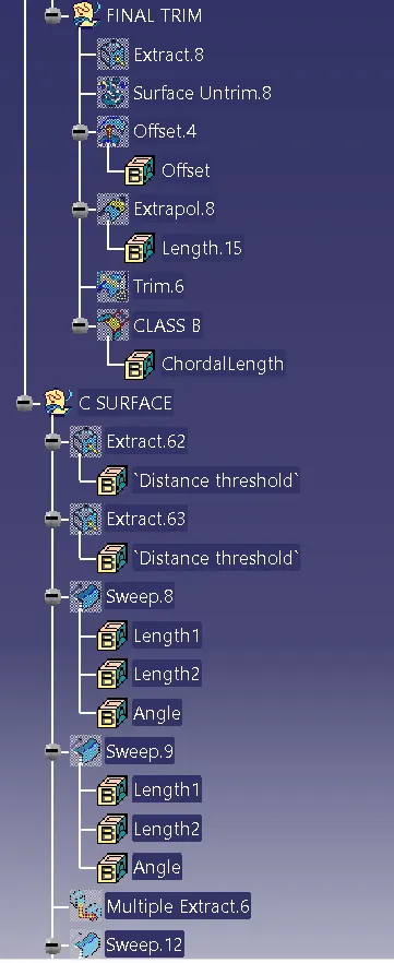
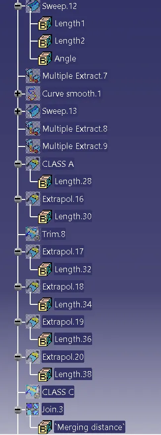
After creation of the class A and class B surfaces of the component we will create a class C surface which is a combination of both the two surfaces.
In injection molding technique the minimum draft angle is maintaining is about 3 degree which is more and easily available content of the draft analysis.
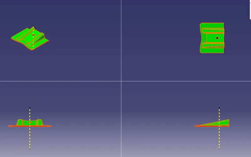
After creation of the axis system take a intersection definition by selecting the zx plane to get a separate two lines by intersecting with a base bracket component.
We have to create a dummy tooling axis in the middle of these two lines of the surfaces.after creating a two lines with the parallel lines just hide the dummy tooling axis and surfaces lines and so that later create a bisecting lines by selecting the two lines which are coincide with each other.
Create a tooling clearing x direction by selecting the plane command in zx direction by selecting the tooling axis and all, which are more precise to each other.Like in a same way we have to create tooling axis of y direction of a component.
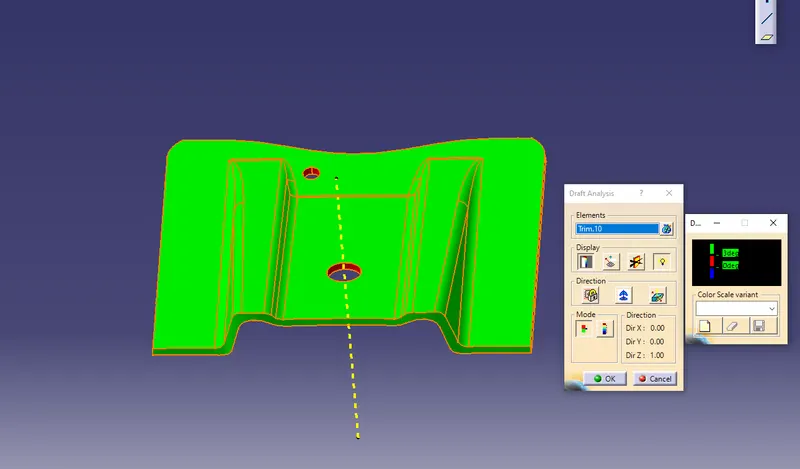
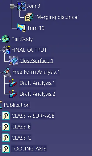
After publicatiion of axis system between the base bracket go to insert option and choose analysis and feature draft analysis option by unhiding the component.
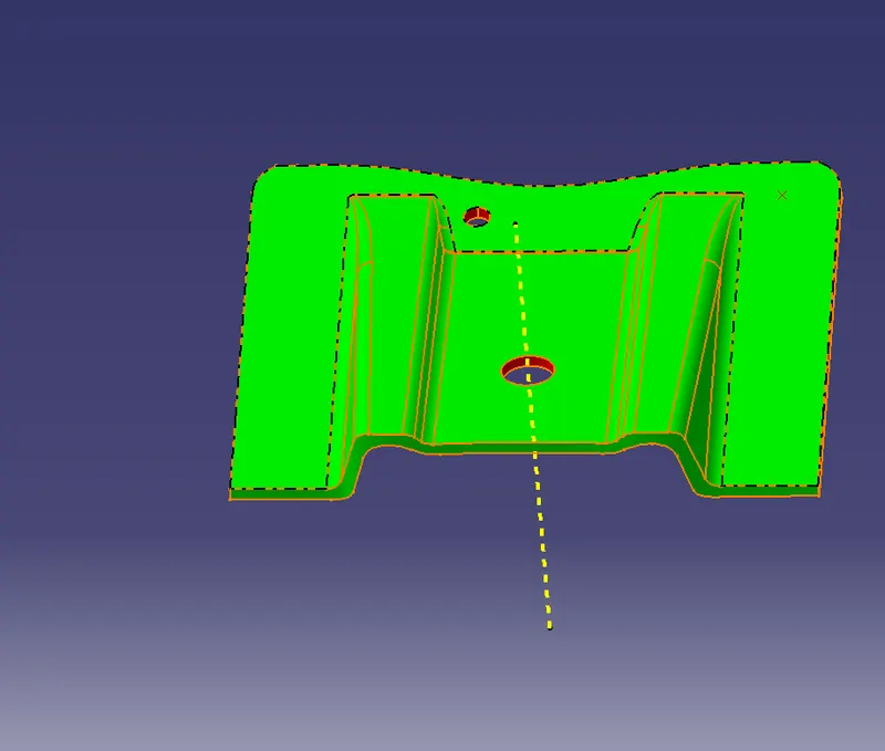
After locking the tooling axis of a system and by providing the draft angle of minimum pf 3 degree by selecting the display option which is present in the draft analysis option.
After placing the dummy tooling axis on a class A surfaces pick on a surface which is completely in green color.
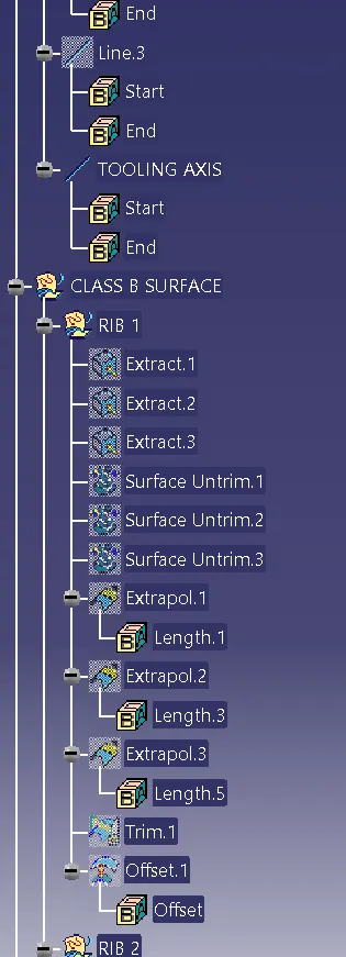
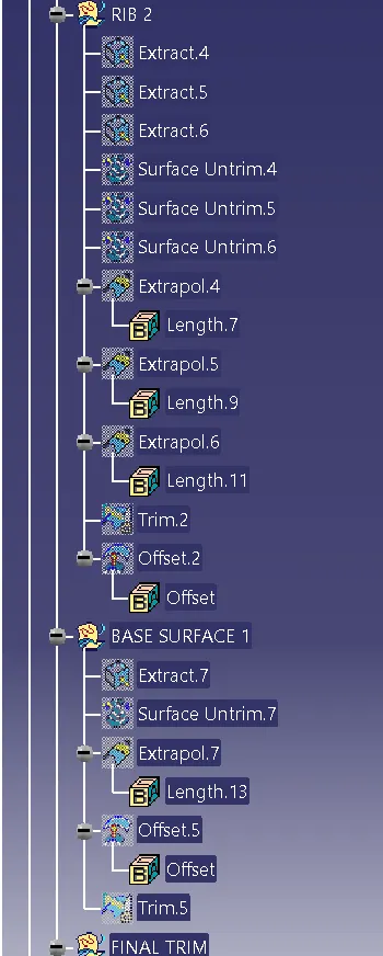
By selecting the rib1 and rib2 of a base bracket component then select the three faces of base bracket by conducting the untrimming options and extrapolate to a distance of specified lenght.
After doing this select the offset option at a distanxce of 2.5mm from the base component and unhide the class A surface and then lock the component.
There will be no gap between the two components which are more efficient to each other.by combining the class A and class C surfaces with bisecting with each other the gap is filled up with a minimum thickness of the component.