Week 8 - Challenge 1 - Draft Analysis on a Fan Cover
The report on draft analysis is done by creating a fan cover is by considering the draft analysis of the component.
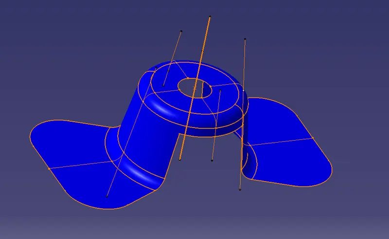
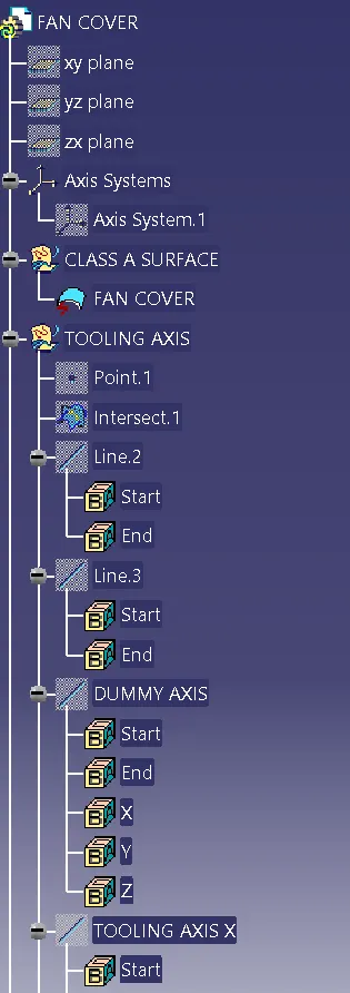
- To create a tooling axis take a bisection of the fan cover model with a plane definition.
- With a selection of midpoint of tooling axis of a fan cover, the axis system should be taking from insert option with a midpoint of a fan cover.
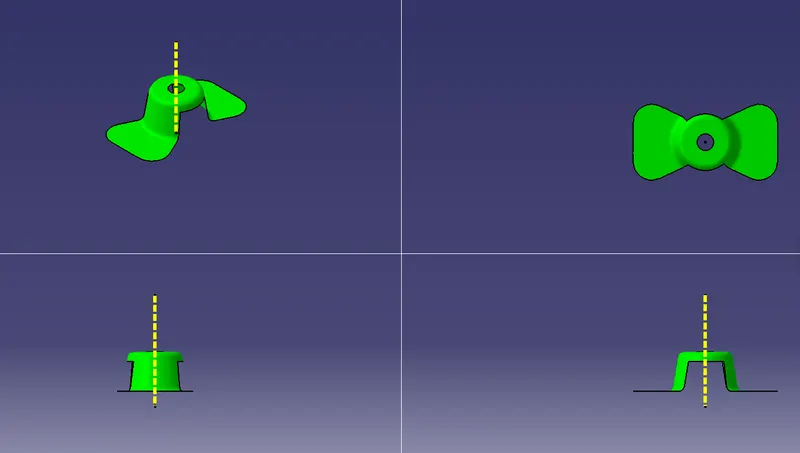
- After creation of the axis system take a interection definition by selecting the zx plane to get a separate two lines by intersecting with a fan component.
- The minimum draft angle of 3 degree sholud be maintained to overcome the uncertainity of the draft component.
- The red color of the draft angle should come in contact with the tooling axis which is more efficient to the draft angle.
- The way of creating a bisection method is done by creating a dummy tooling axis in the middle of the two lines of a surfaces.
- After creating two lines with the parallel lines, just hide the dummy tooling axis and surfaces lines and after that create a bisecting lines by selecting the parallel lines between them.
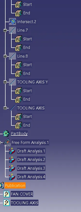
- Creating tooling clearing x direction by selecting the plane command in zx direction by selecting the tooling axis and all, like as same create a tooling clearing y direction by selecting the tooling axis system.
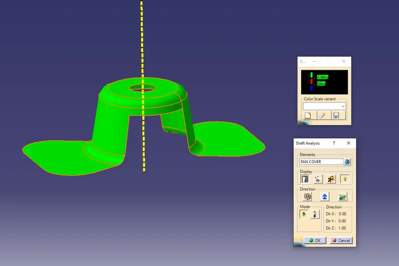
- After creating publication axis system between the fan cover go to insert option and analysis and feature draft analysis option by unhiding the components.
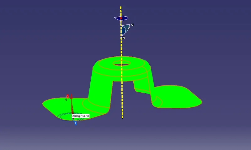
- After locking the tooling axis of a system and giving the draft angle of 3 degree by selecting the display option.
- after placing a dummy tooling axis on a class surface pick on surface which is completely in greeen color.
- The one which is below the surface is called a core and above the surface is called as a cavity.
- If draft direction doesn't meet the tooling axis of the component we should create a side core tooling axis to meet the draft analysis of the fan cover component.