Week 8 - Challenge 3 - Switch Bezel Design
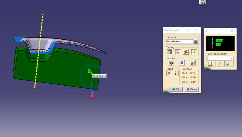
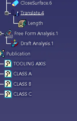
The draft analysis of the component can be done by considering the following steps.
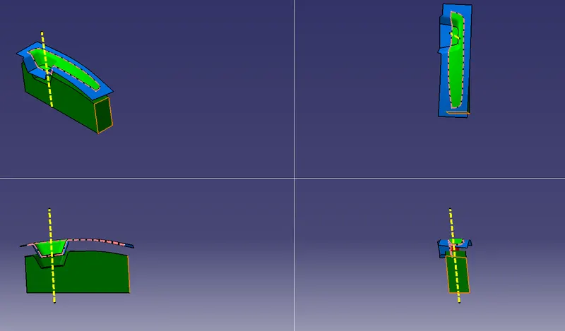
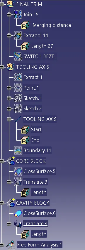
To create a tooling axis take a bisection of the switch bezel which is most used method of the injection molding operation.
With the selection of the midpoint of the tooling aaxis of switch bezel we neeed to considered the axis point creation of the component.
By considering the midpoint of the tooling axis which comes in contact with axis line creation, by some point of time which is nearer to the component.
By intersecting the point which are created on the axis point comes in contact with other.
After creating the axis system consider the intersection definition option by selecting the zx plane command to get a separate two lines which are intersecting with each other.
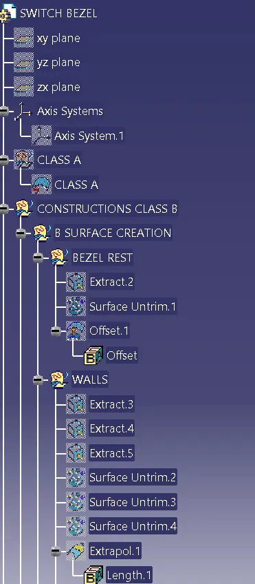
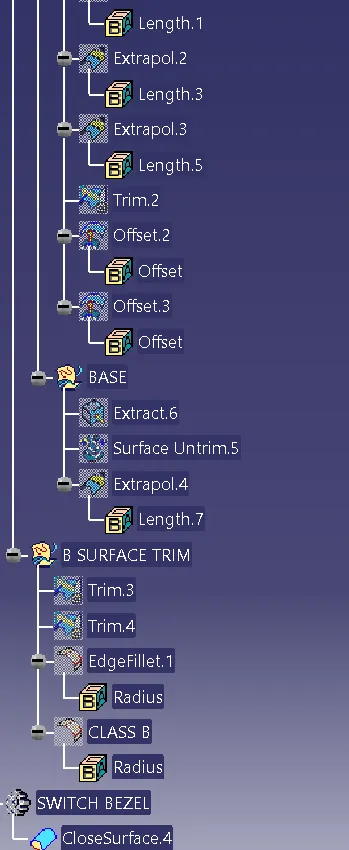
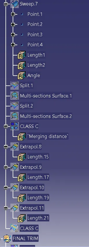
After creating a class A surface with a base component if any gap between is araising just go to extrapolate the command and trim it after the component.
Then by creating the class A and class B surface combine with other and trim it after some extent and remove the unwanted material.
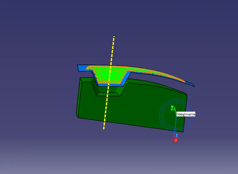
The gap between the two component is filled with a minimum of 3 degree angle which is quite common in molding operation.
The green color indicates that drafting angle of the component is above the 3 degree of the switch bezel.
The blue color indicates the drafting angle is in between the 0 degree to 3 degree minimum of the component.
The red color indicates the drafting angle is below 0 dergee or it is negative of the component.
The draft analysis of the component is done by considering the minimum draft angle which is considerably quite good for the molding operation.
There will be no patches araising between the component which are more complicated to the design component.
The edge fillets of the component can be done after the creation of all three surfaces of the component.
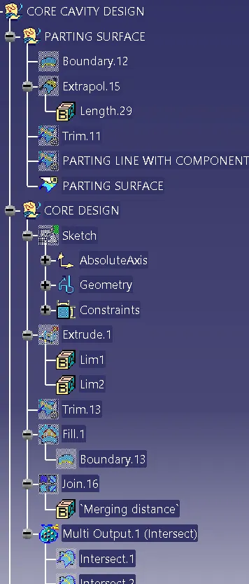
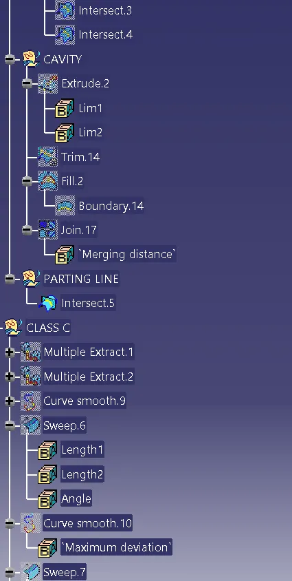
The core and cavity of the component can be made in between the two axis tooling objects.
The one above the surface component is called as cavity and one which is below the component is called as core.
The thickness of the component can be maintained all over the switch bezel tooling axis is around about 2.5mm throught the surface.