Week 11 - Final project
Final Project
Abstract
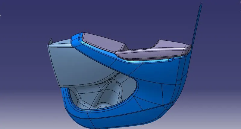
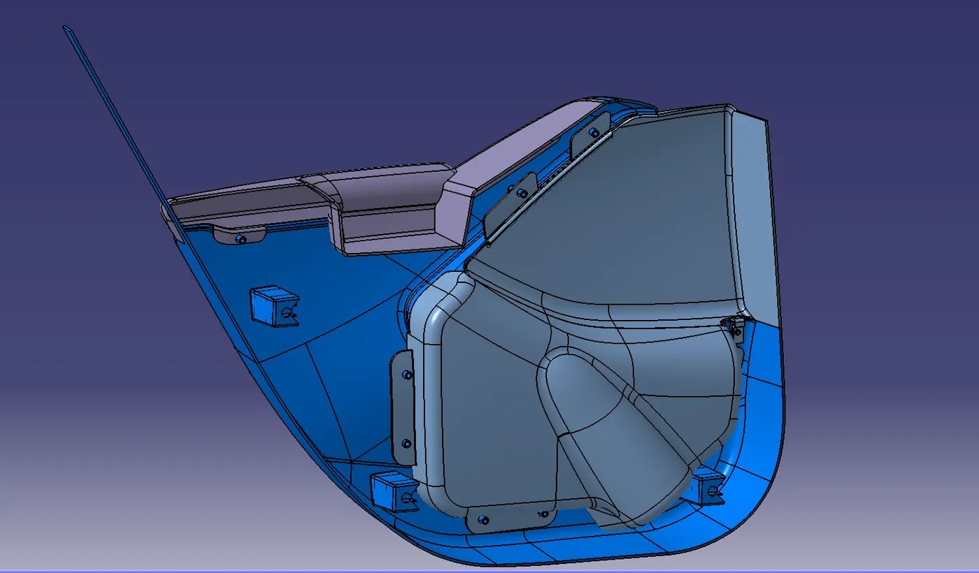
The door panel is the interface between the interior of the car and the inner workings of the door, Generally, the door panel is divided into parts for the ease of designing like the ones created here are Arm Rest, Map Pocket, and the Lower Substrate. These especially require one of the toughest requirements among the interior parts of the car, they should be designed to withstand the load while being less than 2 mm in thickness and also to protect the occupants during collisions.
Nowadays, the door has an inner full-width panel consisting of electronic windows, a central locking system, and speakers. These panels typically consist of foamed core covered with either textiles or plastics.
Product Development Process (Design Cycle in Automotive Industry)
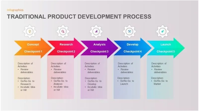
- Concept/ Ideation
This is the concept and ideation stage during which a product’s functional and performance requirements can be defined along with buyer’s ideation, as well as customer requirements and innovative design ideas are explored freely to find the solutions to the present market need.
- Feasibility study and design planning
The feasibility phase allows the management to evaluate a project’s potential, reviewing the project from various business angles, during this phase, the project team reviews product design concepts. Then they select the design which suits the best according to the user requirements.
- Design and Development
In this phase, formal engineering specifications are created. Verification and validation plans are developed for future instances. These are the final quality checks that will systematically determine that all the agreed specifications are present and working in the end product. Then the product is developed according to the designs, with regular checks made throughout the process to access and lower the of its failure for the end-user and the project itself.
- Testing and Verification
Comprehensive testing of the final product takes place to evaluate the robustness of the design and its ability to meet the customer requirements. Verification takes place against the design requirements identified in Stage 2.
- Manufacture/ Launch
Plans specifications and other relevant documents are transferred to the manufacturer for production or software products and updates are released to the customers. After this stage marketing and launch plans are finalized and activated in that process.
- Improvement
The new product becomes part of the company’s portfolio on-going product management ensures the product is subjected to continuous upgrades and improvements.
The stages of the Design Life Cycle is
Concept Sketches:
Concept sketches are rough ideas of free-hand sketches obtained through styling teams and will be used to prepare the model. It is usually done through pen and paper and the painting software. This will be used to generate the concept for preparing the model by incorporating various styles and information obtained through stakeholders.
Class A creation:
After finalizing the concept, the sketches are usually worked in software such as Autodesk Alias to create the CLASS A surface.
Clay Modelling:
The CLASS A Surface is concurrently worked by the clay modelers to brainstorm and benchmarks the styling of the product and later the concept is validated by bringing up a rough clay model and then it is passed on to the design team for the preparation of New Product Design (NPD) CAD.
NPD CAD:
This is where the development of surfaces to parts in CAD kick-off and design engineers’ involvement is vital in this stage.
The designers will work on the input CLASS A surface which is validated by the feasibility team
The procedure followed in the creation of the plastic NEW PRODUCT DESIGN are:
- Tooling axis
- B Surface Creation
- C Surface Creation
- Closed Body Creation
- Draft Analysis
What is Generative Shape Design?
The Generative Shape Design provides an extensive set of tools for creating and modifying mechanical surfaces used in the design of complex shapes or hybrid parts, Its feature-based approach offers a productive and intuitive design environment to capture and reuse design methodologies and specifications. It helps to design advanced shapes that are based on a combination of wireframe and extensive multiple surfaces which includes high-level features with full specification capture and reuse.
What is Draft Analysis?
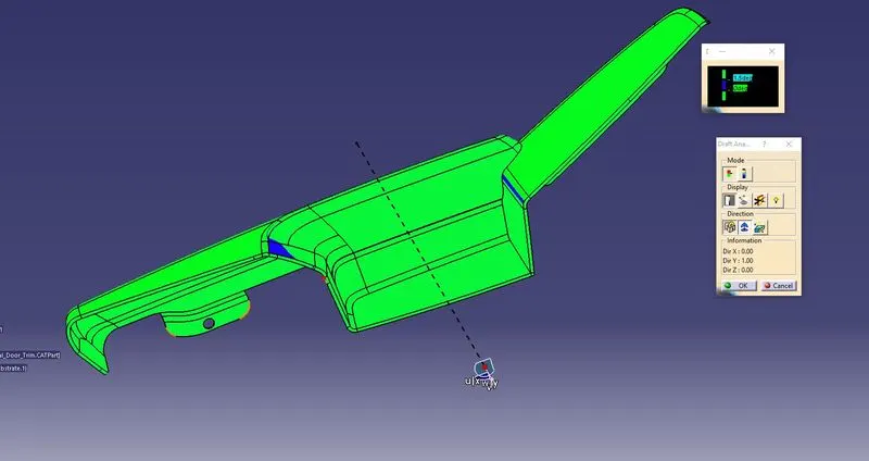
The Draft Analysis command enables you to detect if the part you drafted will be easily removed, this type of analysis is performed based on color images identifying zones on the analyzed element where the deviation from the draft direction at any point corresponds to specified values.
No parts can be ejected from the tool if it is having a straight 90-degree profile from its base surface, a small draft angle is provided to every area of the component to get easy removal of the component from the tool. The draft analysis technique is used to analyze whether our part model created in cad is manufacturable based on the draft condition applied.
In the molding process, the molded parts have to eject from the die so there are some issues while removing the molded parts it may get sticky with the die, or while removing the chances to get damaged, so we need to set up is the draft angle this draft angle helps the molded part to eject from the die easily.
PROCEDURE OF PART CREATION:
- Input Given:
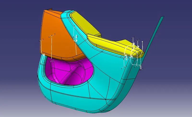
Interior Door Trim consists of four Components:
1. Lower Substrate
2. Map Pocket 1
3. Map Pocket 2
4. Arm Rest
- Class A Surface:
In Automotive design, a Class A Surface in any of a set of freeform
surfaces of high efficiency and quality. Although strictly, it's nothing more than saying the surfaces have curvature and tangency alignment- to ideal aesthetical reflection quality, many people interpret Class A surfaces to have G2 or even G3 curvature continuity to one another. Class A Surfacing is done using computer-aided industrial design applications. Class A surface modelers are also called "digital sculptors" in the industry. Industrial Designers Develop their design styling through A-Surface, the physical surface the end-user can feel, see, touch, etc.
Door Arm Rest
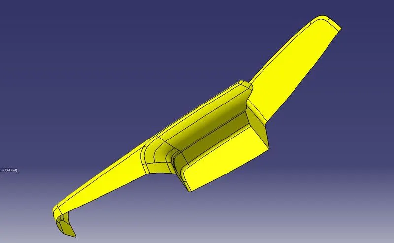
Map Pocket
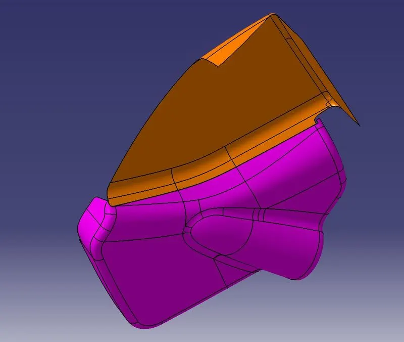
Lower Substrate
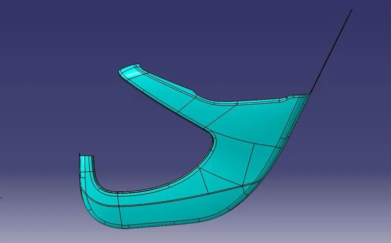
- Tooling Axis:
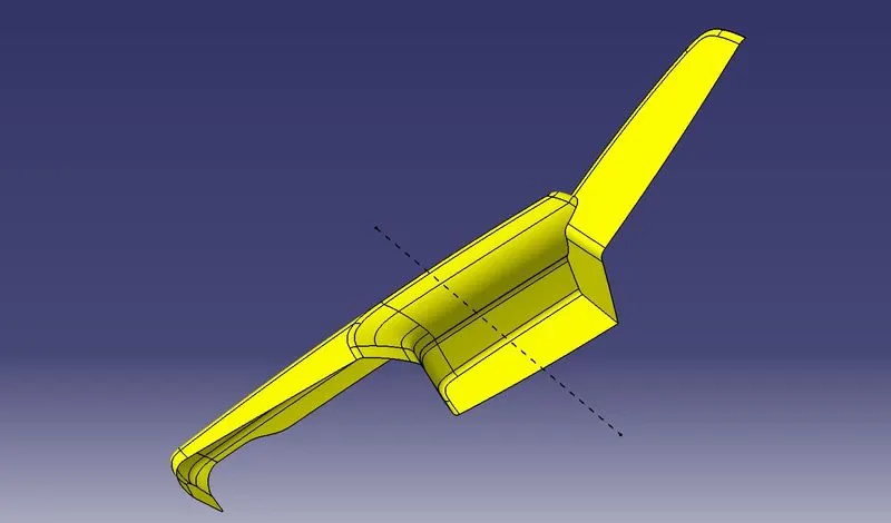
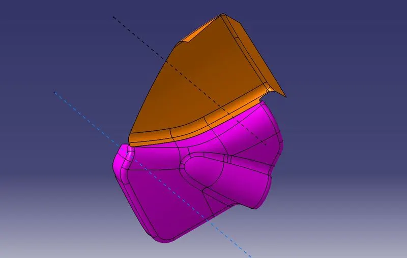
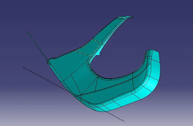
The tooling axis is nothing but the direction in which the core and cavity opens and closes. The design engineer works on it to analyze the Class-A surface and finds out the best possible tooling direction keeping in mind all the draft angles is concerning the tooling axis so that the component can be easily ejected from the molds.
Door Arm Rest
Map Pocket
Lower Substrate
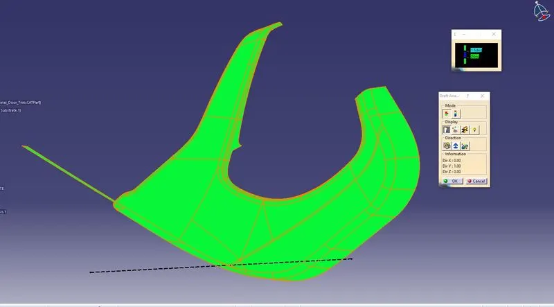
- Draft Analysis:
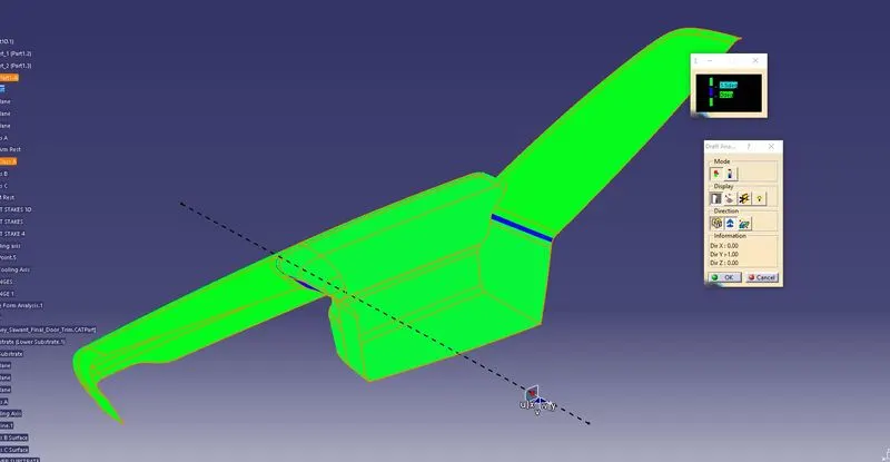
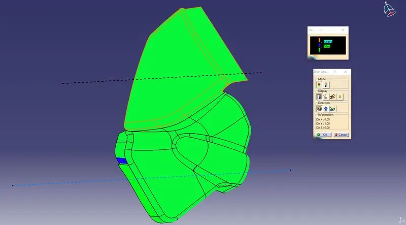
The Draft analysis command enables you to detect if the part you drafted will be easily removed. This type of analysis is based on color ranges identifying zones on the analyzed element where the deviation from the draft diction at any point, corresponds to specified values. Draft angles are very important in thermoforming product designs. If the product is formed onto a female or negative mold, it shrinks away from the mold sidewalls. As a result, true
female or negative products can be thermoformed with vertical walls having zero draft angles. Parts cannot be ejected from the tool if it is at 90-degree surface. For that reason, a small draft angle is to be provided for every surface of the component to easy removal of the component from the molds without any defects. Most of the parts require a minimum of 0.5 degrees to 1 degree, however, 3 degrees are widely accepted in plastic component design. Draft analysis is the technique used to analyze whether our designed products are manufacturable with required conditions are not.
Door Arm Rest
Map Pocket
Lower Substrate
- Class B Surface Creation:
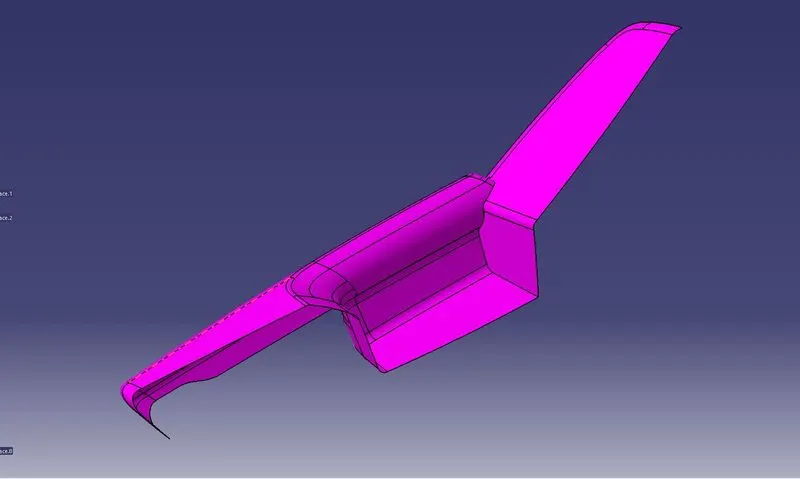
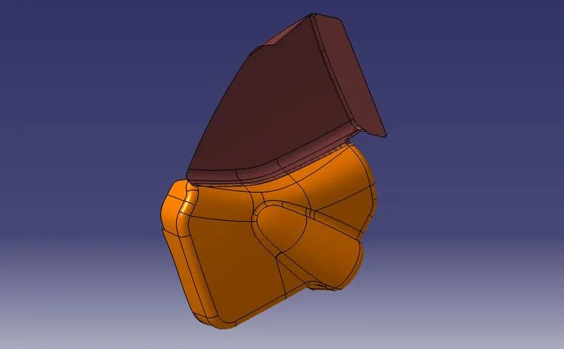
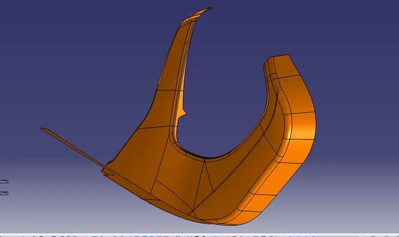
Class B surface includes derived surfaces created by offset operations from Class A surfaces to define the thickness Of the material. In this file, it is important to link Class B Surfaces geometrically to enable an adaptation to Class A surfaces Automatically in case of styling change
After creating the tooling axis, a B surface is to be created which is nothing but the surface parallel to the A surface. B surface contains all the fillets and the edges which the A surface contains.
Door Arm Rest
Map Pocket
Lower Substrate
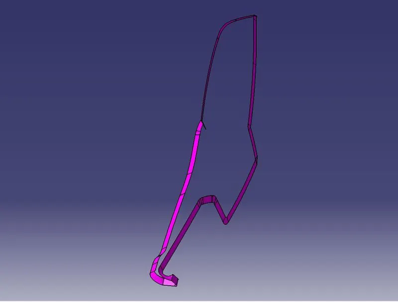
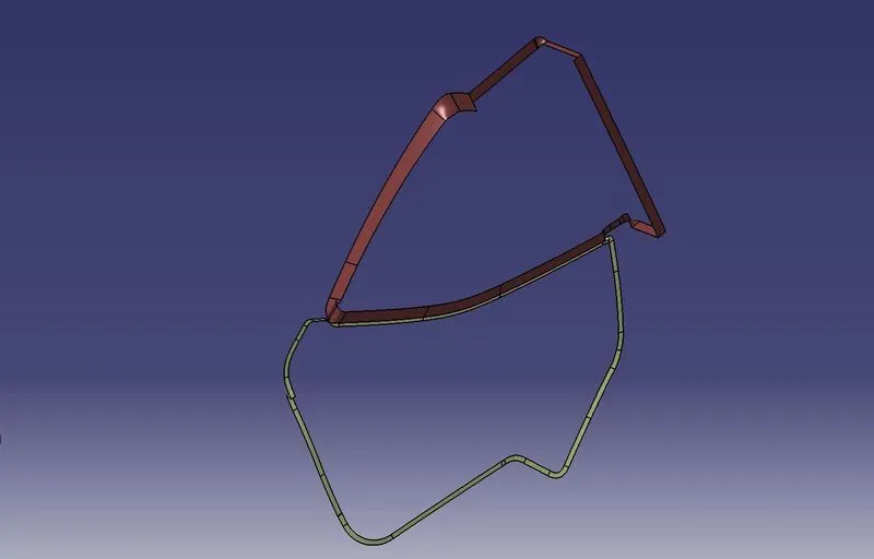
- Class C Surface Creation:
Class C Surface is swept along the boundary of Class A at an angle perpendicular to the Class A Surface.
* concerning the tooling axis direction with a draft angle of 3 degrees.*
Door Arm Rest
Map Pocket
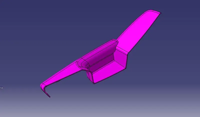
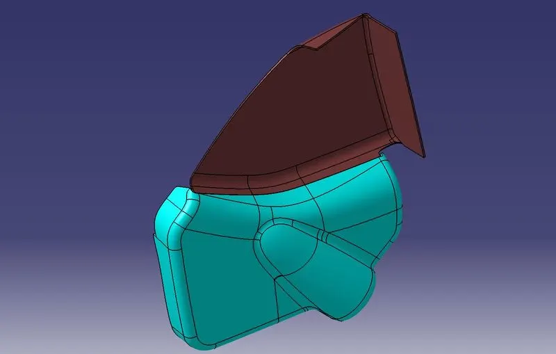
- Joining Class, A, B, and C Surface to get a Closed Surface:
After finishing all the 3 surfaces, join the Class A and Class C surface together using the Join command, Now the joined surfaces are then trimmed concerning the Class B surface to form a Closed Surface
Door Arm Rest
Map Pocket
Lower Substrate
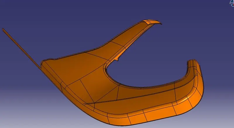
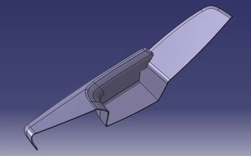
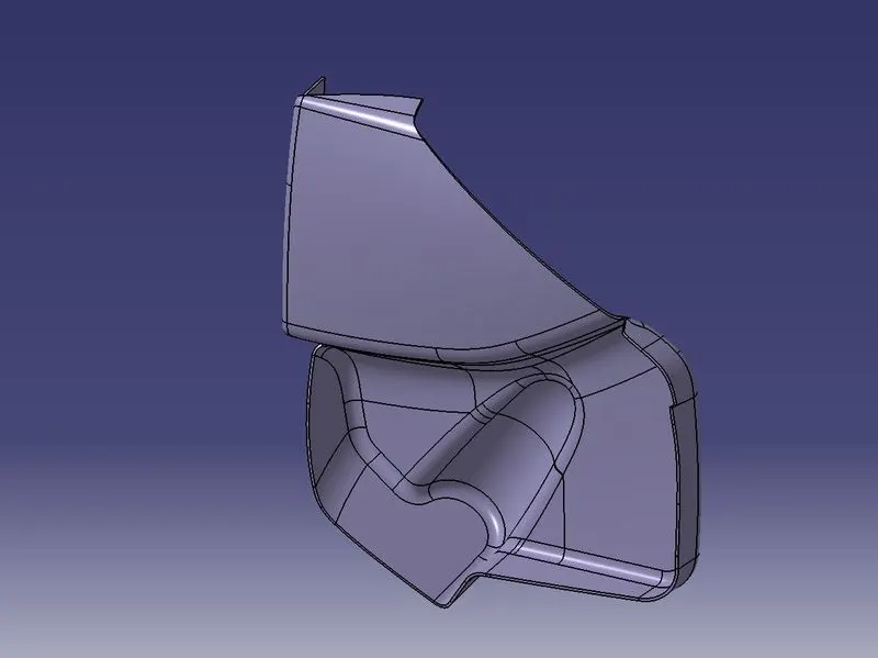
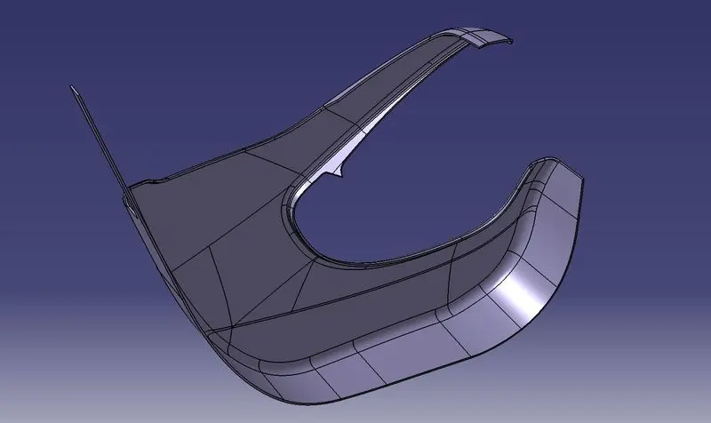
Now, We create the Closed Surface into Solid Bodies as shown below.
Door Arm Rest
Map Pocket
Lower Substrate
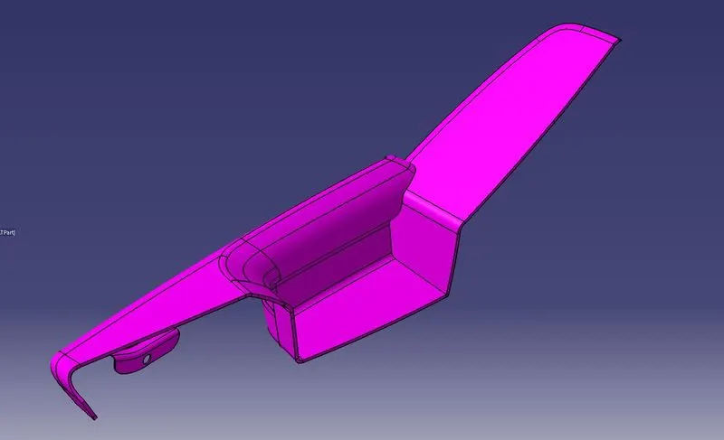
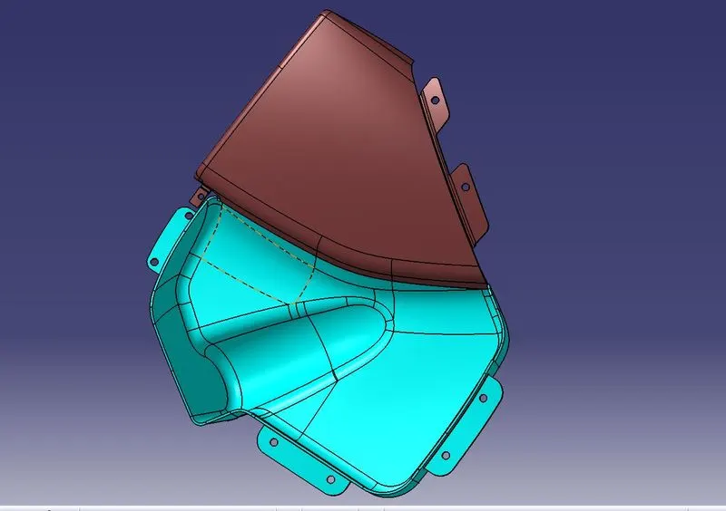
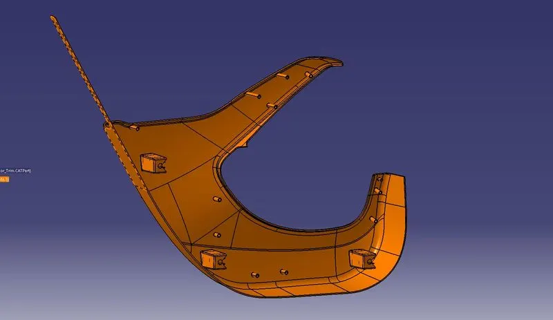
- Creation of Flanges, Rib, Dog House, and Heat Stakes:
Dog House:
Create the Dog House as per the design rules and give the required draft angle.
Dog House wall thickness at the intersection of the part Wall(C) should be 40% or
less than the main wall stock(T)
• Height of (B) should be between 3-6 mm.
Ribs:
Create the ribs as the design rules and give the required draft angle, Ribs are created to
increase the stiffness and strength of the surface
Heat Stakes:
Heat Staking is a pulsed-heat process to join two or more parts out of which one
at least is made of plastic.
The process is to deform the plastic material using heat and force at a set process time.
The bond is made by partially deforming the plastic part to fix the other.
Door Arm Rest
Map Pocket
Lower Substrate
- Draft Analysis for the Final Component:
Door Arm Rest
Map Pocket
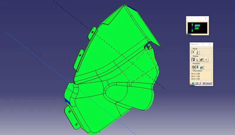
Lower Substrate
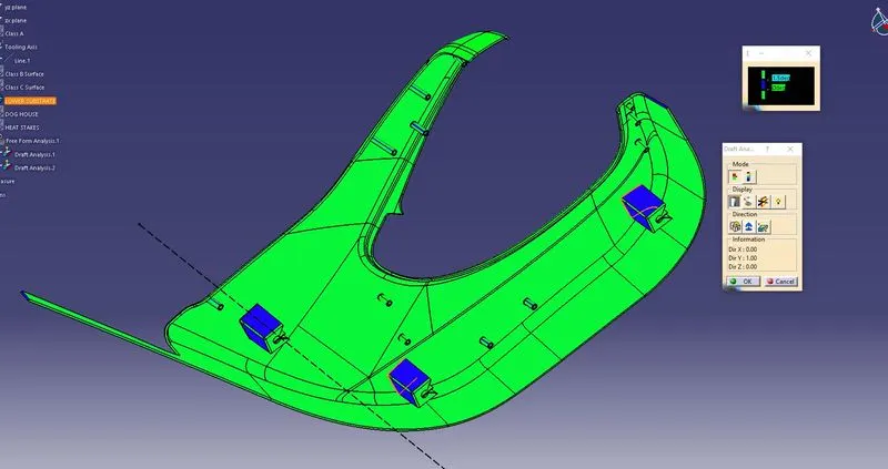
Surfaces that are not clearing the Draft Analysis need improvement in the Class A surface.
- Final Model Images: