Week 11 - Final project
CAD modeling and development of door trim panel – Automotive interior plastic components
OBJECTIVE
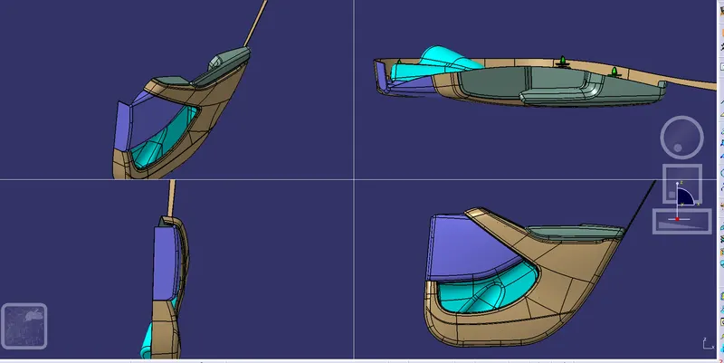
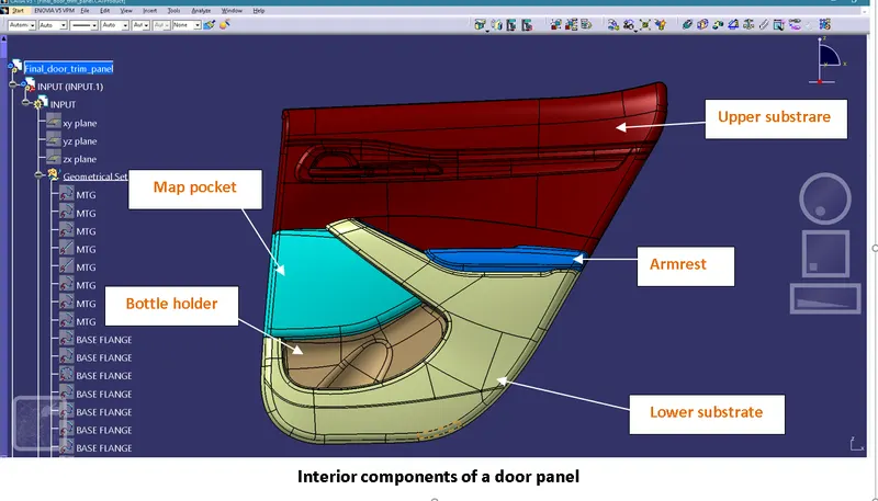
This project intends to develop the door trim components from the surface and master section. CAD modeling of the armrest, map pocket, bottle holder, and Lower substrate is developed in this project. The design tool used in this project is Catia V5.
- Create a tooling axis for the given Class-A surface and make an initial draft analysis
- Create Class B and C surface from the given class A surface
- Develop door trim components from given A surfaces, and Master sections and use modeled B and C surfaces
- Perform a draft analysis for the solid component using the tooling direction
- Develop fixation and features from door trim like a dog house, push pins, flanges, heat stakes, locators, and ribs considering the design rules
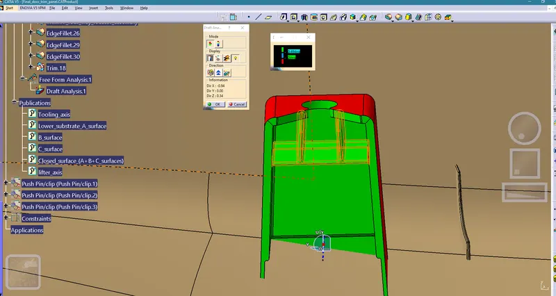
- Draft analysis using lifter axis for the dog house
All these plastic components have to design and develop as per the DFMA (design for manufacturing and assembly) rules used in the automotive industry. The rules include factors such as maintaining constant part thickness, having a universal draft direction, parting line, parting surface, component clearance using draft analysis, and creating the engineering features on the B surface following the design rules.
INTRODUCTION
Automotive door panels consist of several components, where most of the interior parts are manufactured through plastic materials due to several reasons such as being lightweight, and more fuel efficiency, which reduces greenhouse gas emissions. Plastic automotive components also reduce manufacturing and assembly times and repairs, contributing to reducing overall resources and energy used by the industry. Moreover, plastics specifically support a high-quality look and feel of the vehicle interior.
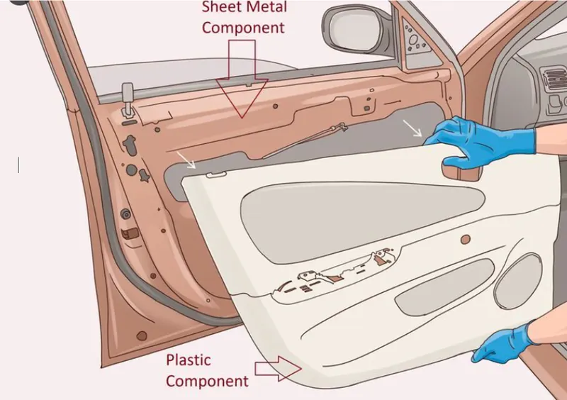
Furthermore, door panels are considered as one of the important components in the vehicle as they provide reliable side protection, ergonomic comfort, and convenience coupled with attractive and soft-touch surfaces. They are usually made up of plastic, steel, aluminum, or mixed material.
MASTER SECTION:
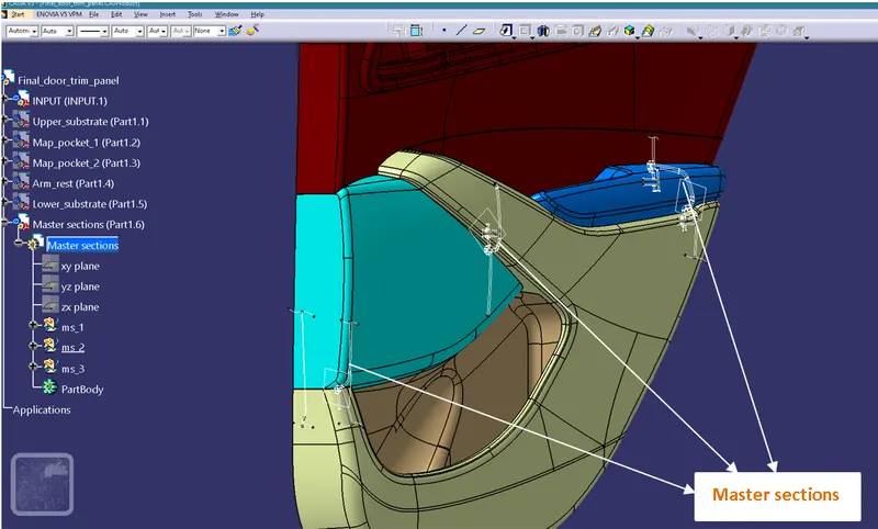
Master sections are the guides for product design requirements that decide the component packaging after technical Styling, Concept, or Class-A surfaces. The master section helps us to decide the feasibility, clearance, and fixation strategy of a component before working it in a 3D.
TOOLING AXIS:
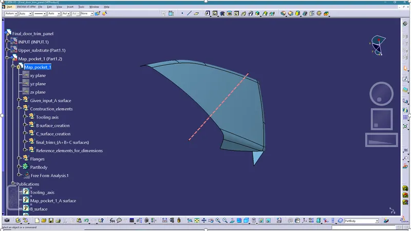
The tooling axis is the direction in which the mold or core and cavity get opened and the component is ejected. Clearance of the component is checked using this tooling axis. This means all the faces of the component when ejected along the tooling axis, must come out of the mold easily, without failing.
SLIDER AXIS AXIS:
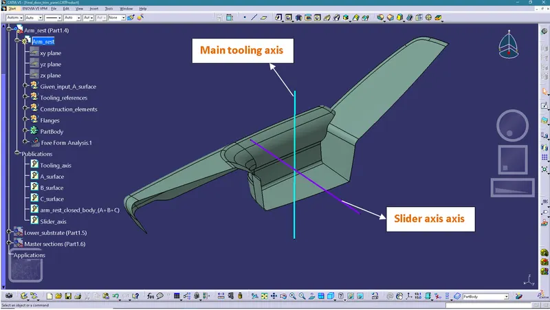
- Generally for all the plastic components tooling axis will be given. But for some components along the tooling axis, a slider axis is also given
- This is because when the components have undercuts, holes, and a few other areas that are not able to clear within the main tooling axis, then a slider axis is introduced
- For example for the below component shown in the figure has an undercut, and it is not possible to clear within the main tooling direction so a slider axis is given.
DRAFT:
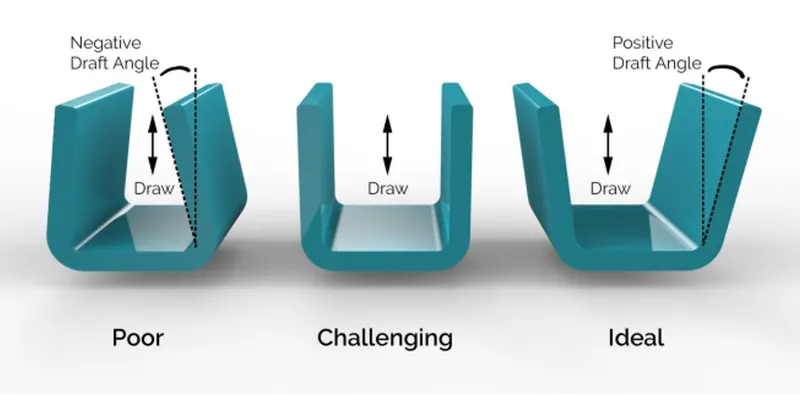
- The draft is an angular tapering given to the plastic component in the design stage. The draft is given in the direction of the mold movement
- To allow the part to eject from the mold easily a draft angle must be added to all vertical walls. This reduces wear on the tool and reduces the possibility of drag marks on the surface of the part.
- Most applications required a minimum draft angle of 0.5° to 1°, however, up to 3° draft angle is given for the cost-saving purpose.
- Furthermore, a 7° draft angels are given to textured surfaces like instrument panels
DRAFT ANALYSIS:
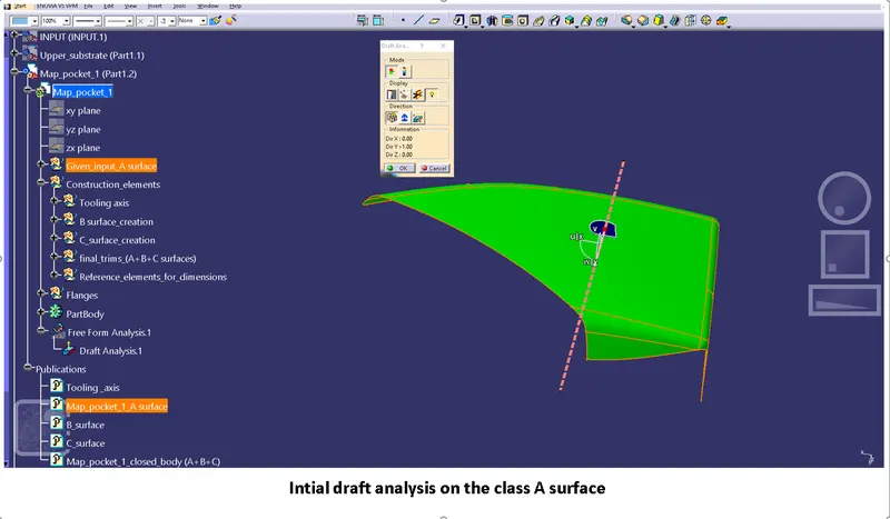
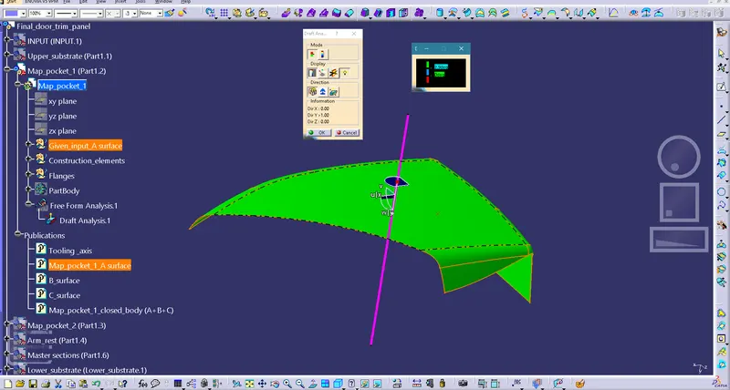
- The Draft Analysis command enables us to understand whether the component that we drafted will be easily ejected.
- This type of analysis is performed based on color ranges identifying zones on the analyzed element where the deviation from the draft direction at any point, corresponds to specified values.
- Generally, draft analysis is performed two times, initially within the given class A and then on the final solid component.
Surfaces of plastic component
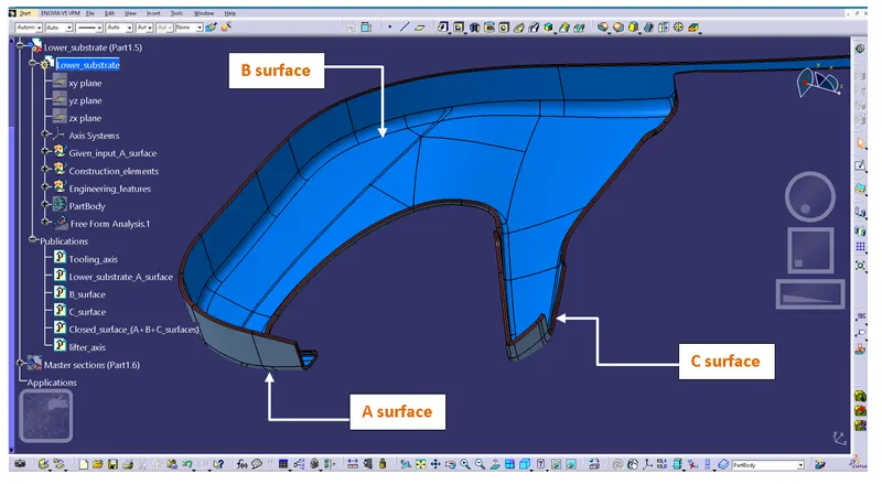
Automotive trim parts have three surfaces those are class A, B, and C.
Class A surface
- Class A surface is a visible surface that has some aesthetic properties, designed with high efficiency and quality
- These surfaces are designed by the designer using the software Alias and give the surface to the product designer to model the complete product.
Class B surface
- B surface is the inner surface of the component, which also has engineering features. This surface is developed by the product designer and gives to manufacturing.
- This surface is designed as per the class A surface maintaining the continuity, thickness of the component, functionality, and so on.
- The engineering features that are included on the B surface are dog house, screw boss, ribs, locators, stiffeners, and flanges
- This surface is inside and not visible to the passenger
Class C surface
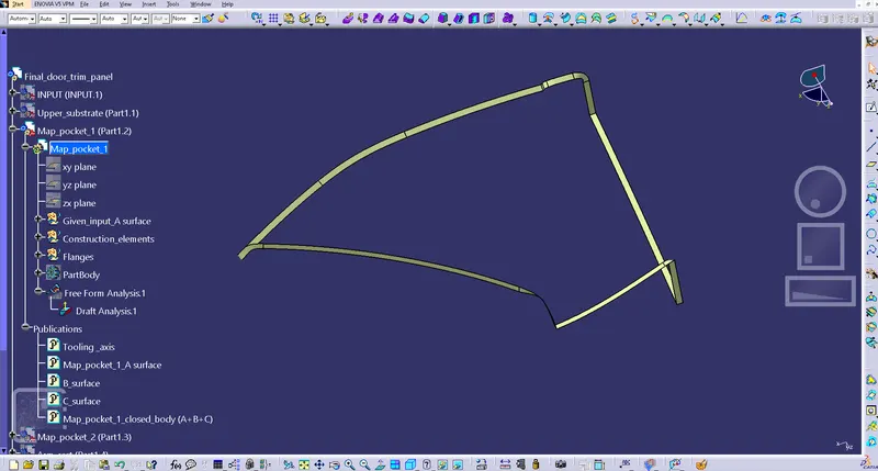
- C surface is designed to join the class A and B surfaces.
- This surface is created along the tooling axis with a specified draft on it.
- It is the thickness region in between A and B surfaces
FEW POLYMER MATERIALS USED IN THE DOOR PANEL ARE:
- ABS
- PC-ABS blends
- Polypropylene
- Reinforced elastomer
Factors in plastic product design for manufacturability
Designing a plastic part for manufacturability involves many important factors that touch on all areas of part design, tooling, material selection, and production. Here are 8 important factors to consider to meet your plastic part design goals for a successful production process.
- Material consideration
A material consideration is a complex task and it is chosen based on many considerations such as temperature, chemical resistance, finish, assembly, cost, and availability. Manufacturers often select a familiar grade of plastic from a similar application or rely on recommendations from suppliers.
- Radius
The radius should always be a consideration regarding the part’s thickness – eliminating the likelihood of areas of high stress and possible breakage of the part. A general rule of thumb is that the thickness at a corner should be in the range of 0.9 times the nominal thickness to 1.2 the nominal thickness of the part.
- Wall thickness
Maintaining the consistent wall thickness helps avoid many part defects that can occur during the manufacturing process. The nominal wall thickness of a plastic component is 3mm. A deviation of 30% from the wall thickness is allowed with a gradual increase or decrease to avoid any plastic defects.
For example, a component with a wall thickness of 3mm has a deviation allowance of a minimum of 2.1mm and a maximum of 3.9mm
- Gate location
Gates are critical to making sure the resin flows properly into the mold. These small components of your design are what direct the flow of resin from the runners to then be distributed through the part. the kind of gate and placement has a crucial impact on the part’s overall quality and viability.
- Draft
The draft is that the amount of taper on the vertical walls of the plastic part. Without the draft, the part might not eject from the mold or may sustain damage during ejection. Typically, draft angles between 1° and 2° are required but a draft angle of 3° is given and can vary looking on part restrictions and specifications.
- Ribs
A plastic part that has been designed with a minimal wall thickness won't be as strong as a thicker part – which is why the inclusion of ribs is also needed to assist reinforce the part’s strength. Depending upon the material used, rib thickness should be between 50 – 70 percent of the relative part thickness to avoid sink marks.
- Mold shrinkage
The shrinkage that happens during the plastic part molding process is the maximum amount as 20 percent by volume. Crystalline and semi-crystalline materials are most vulnerable to thermal shrinkage. Amorphous materials are known to shrink less.
- Special features
plastic parts should be designed so that mold tools open and eject the part easily. When a component is released, the 2 sides of an injection mold separate within the wrong way. When special features like holes, undercuts, or shoulders prevent the discharge from happening, it's going to be required that side actions be incorporated into the design.
Side actions pull coring in a direction other than the direction of the mold separation. This adds flexibility to the part design and at times, may increase the cost of the mold.
ENGINEERING FEATURES (B side features)
There are different types of engineering features used in plastic component design. Each type of engineering feature has an individual purpose such as strengthening the component, assembly, fixation, and so on. And each of them is designed following some individual design rules. Few features used in this project for the design of the components are a dog house, ribs, heat stakes, and a 4-way locator.
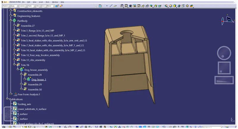
DOG HOUSE
- The dog house is an engineering feature used in the plastic trim design.
- The primary purpose of the dog house is to avoid sink marks
- Its secondary use is to mount thick screw boss or locator pins over it.
- Dog house and other engineering components are built on B-surface
Guidelines followed in designing a dog house
To avoid plastic defects few design guidelines are followed and the features are designed. Things that need to be considered in a dog house design are
- Wall thickness of the dog house = 0.7*T
- Fillet on the inner side = 0.25*T
- Fillet on the outer side = 1.25*T
- Coring thickness = 0.4*T
- Draft angle = 2 to 3 deg
- Coring height is maintained at 4 to 6mm
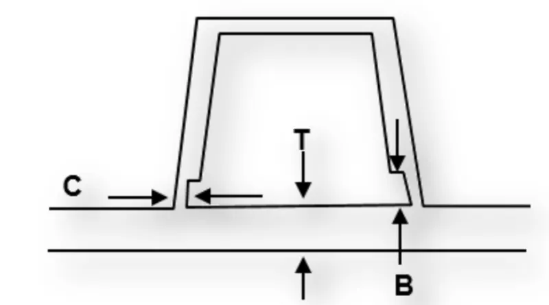
In the above figure, C is the coring thickness
T is the thickness of the component
B is the coring height
RIBS
- The rib is an engineering feature designed on the B side which provides economical stiffness and strength to the plastic component
- Ribs also reduce the necessity of increasing the overall wall thickness of the component
- It facilitates locating and arresting components of an assembly
- It also provides alignment in mating parts and acts as a stop and guide for the mechanism
Guidelines followed in designing the ribs
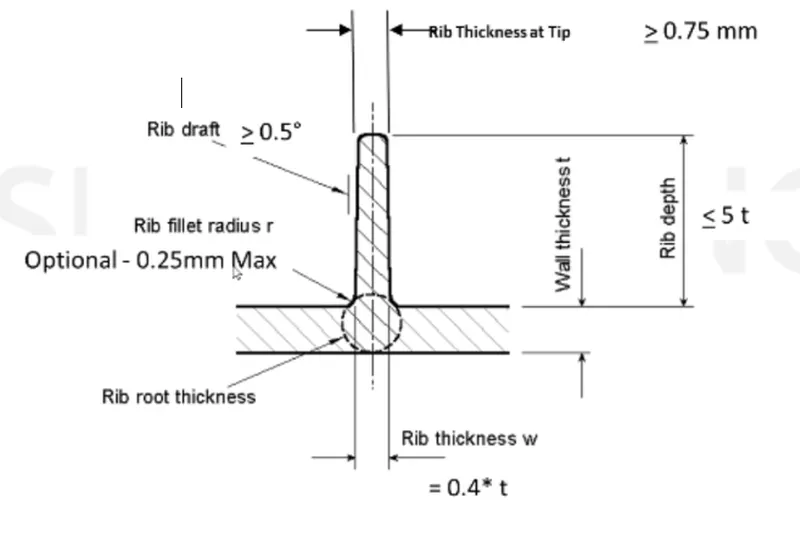
- Draft - We know the draft angle of 3° is ideal for any surfaces in the plastic component. But for the ribs, 0.5° per side is the minimum.
- Wall thickness of the ribs - The wall thickness of the ribs can be 0.4 * wall thickness of the component. If t is the wall thickness of the component, then the wall thickness of the rib is 0.4*t
- Minimum wall thickness at Rib tip - The tip of the rib should maintain a minimum wall thickness of 0.75mm. Less than that is not advisable. Because after changing the flow direction of the molten material, it is not easier to reach the very thin area. For ribs, it takes a 90° deviation from the main flow direction.
- Rib fillet radius (r) - Optimal rib fillet radius is 0.25mm. But if the component is thicker, we can go until 0.5mm. Above that is not advisable.
- Rib Depth/Height - Rib height must be 5*the component wall thickness
- Spacing b/w ribs - Ribs should be spaced at the H/W ratio when more than one is there. where H is the height of the rib and W is the width b/w ribs. And the accepted ratio is 3:1
- Rib root thickness - The root thickness should not exceed 30% of the component wall thickness
Locator pins (4 way and 2-way locators)
- The purpose of locator pins is to arrest the degrees of freedom of a component.
- They are classified into two types i.e. four-way locator, 2-way locator, and are rib-like structures
- Here following a 3-2-1 design principle the locator pins are created
- The 3-2-1 principle of location is used to constrain the movement of the workpiece along the three axes XX, YY, and ZZ. This is achieved by providing six locating points, 3 pins in the base plate, 2 pins in the vertical plane, and 1 pin in a plane that is perpendicular to the first two planes
Heat stakes
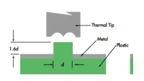
- Heat stakes are used to weld two or more plastic components or dissimilar materials. In other words, it is also known as thermoplastic staking.
- Heat stakes are the vertical cylindrical structures added to the class B surface
- To form an assembly, a plastic stud or boss is given to the child component and a hole for the parent component.
- The boss on the child component is melted then the molten material forms on the parent component. Later the material gets cooled and forms an assembly.
Guidelines followed in designing a heat stakes
- Draft angel generally 0.5 deg is given inner and outer wall. Differ from component to component
- Height of the cylinder
- Diameter
- Wall thickness
- Height above the flange
There are no specific rules for the heat stakes to follow, it depends upon the machining gun and manufacturing process.
In the below-displayed picture in the place of the metal component, it can also be a parent plastic component.
ADVANTAGES
- No need of going for secondary operations like screwing the components
- Simplification of machinery
- Reduce the cost of machinery
- Multiple fastening points
DISADVANTAGES
Once the assembly is done the components cannot be separated without damaging them
Screw boss
- Screw boss is an engineering feature that helps to screw two components. Screw bosses are used to joining and assembling many components.
- Commonly consist of cylindrical projection with a center hole, where it can be threaded by a hardware tool.
- While joining two components using screws and when we don't want those to be visible on the A surface, in that area these bosses are used.
Guidelines followed in designing screw bosses
- To reduce the stress concentration and potential breakage the bosses must have blended radii rather than sharp edges at the base
- Large radius reduces stress concentration but also increase the chance for sink or voids
- Proper boss design is necessary to avoid plastic defects which involve the following critical sections and design rules that need to be considered
- Draft angle
- Thickness at base
- Height/Diameter ratio (H/D)
- Optimal radii for fillets (r)
- Boss gussets for ribs for support
- Root diameter
- Planning for a type of ejection
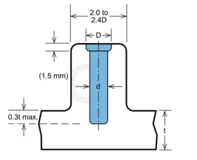
Draft - A maximum draft angle of 0.5 degrees is used inside and outside of the screw boss
Thickness - If 't' is the thickness of the component. One wall of the screw boss should have a thickness of 0.6*t. This is the ideal case but can be increased w.r.t requirement.
Height - The height of the boss has a height to diameter ratio which is 3:1
Fillet radius - A maximum of 0.25mm is given.
The procedure followed for CAD modeling and development of the door trim panel
As mentioned earlier the door panel consists of many components manufactured through the plastic as we as other materials. In this final project mainly the CAD modeling is done on 4 different plastic components. They are an armrest, map pocket, bottle holder, and the Lower substrate.
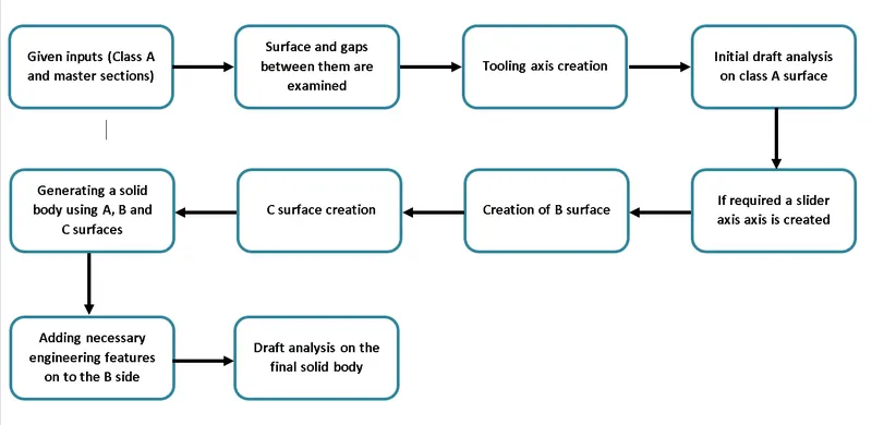
Inputs
Class A surfaces of all components
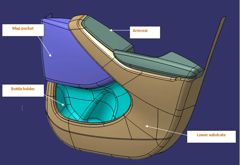
Armrest
Surface check
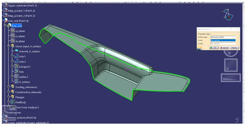
To find out whether, if any gaps exist between the given A surface the boundary command has been used.
Tooling axis
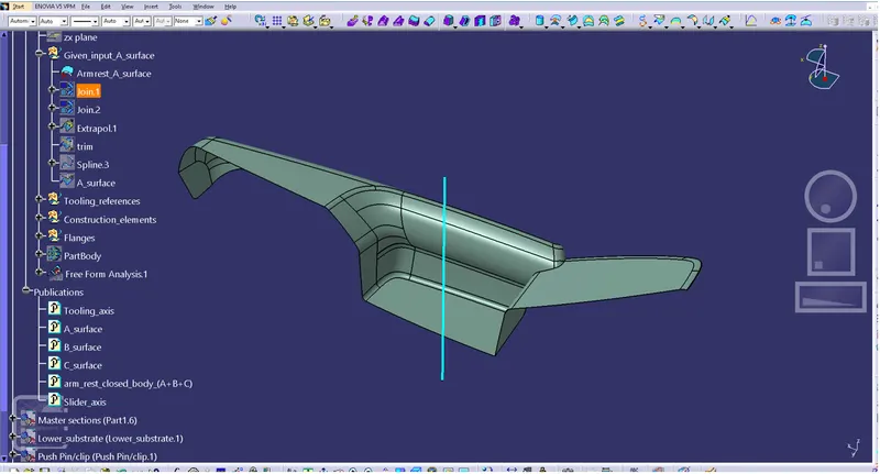
Here for the given component, the universal direction Z is taken as the tooling axis
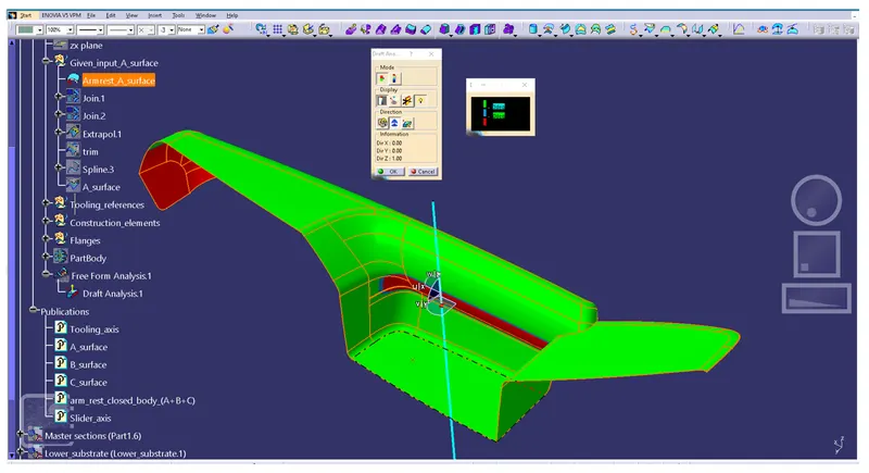
Draft analysis on the given class A along tooling axis
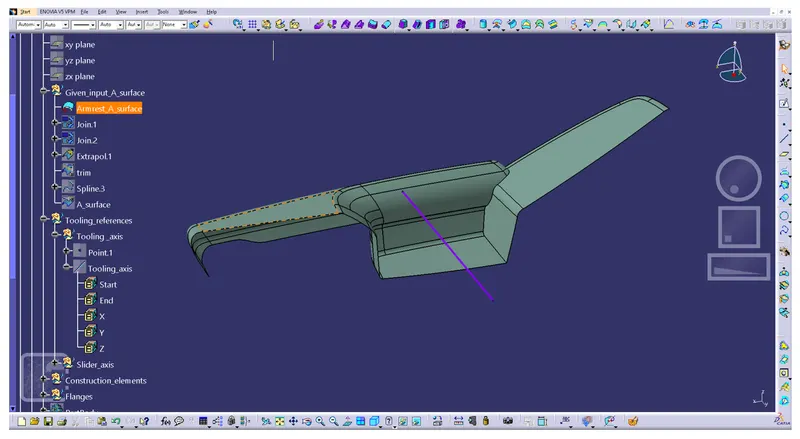
since all the areas are not clearing within the main tooling axis, a slider axis is introduced for this component.
Slider axis
Class B surface
The thickness of the component is 2.5mm. Considering this the B surface is created maintaining an offset of 2.5mm from the A surface.
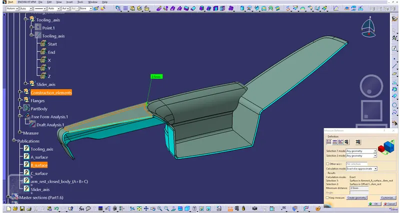
Class C surface
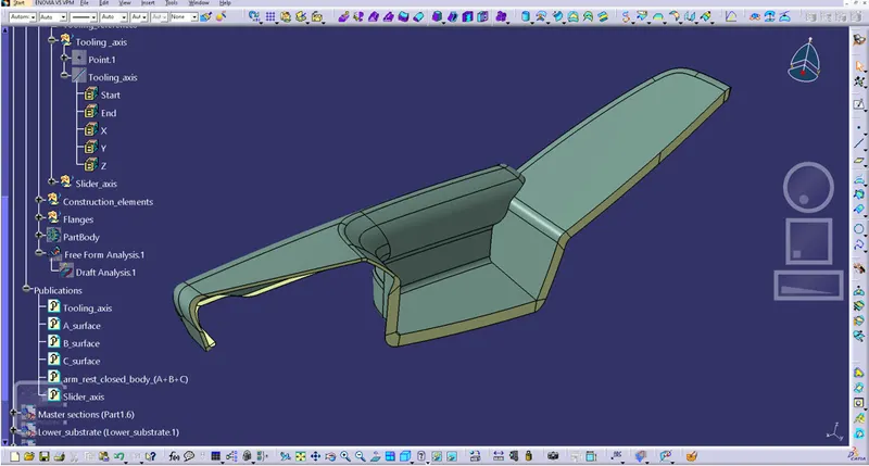
Creation of solid body using above all surfaces
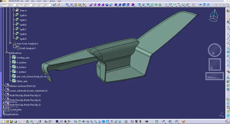
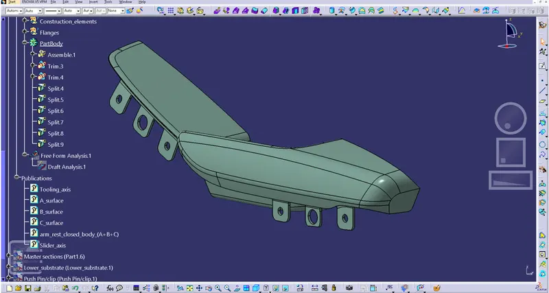
Adding engineering features
Final draft analysis on the armrest
Using main tooling axis
In the final draft analysis, a few areas are not clearing with the given tooling direction. This is because of the problem within the given A surface. Since there is no class A designer the product design is continued without modification to the class A surface
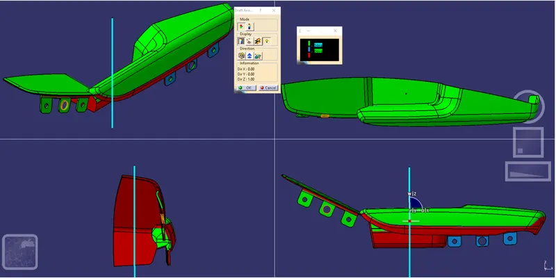
Using slider axis
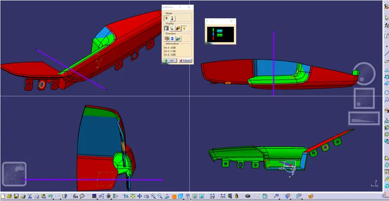
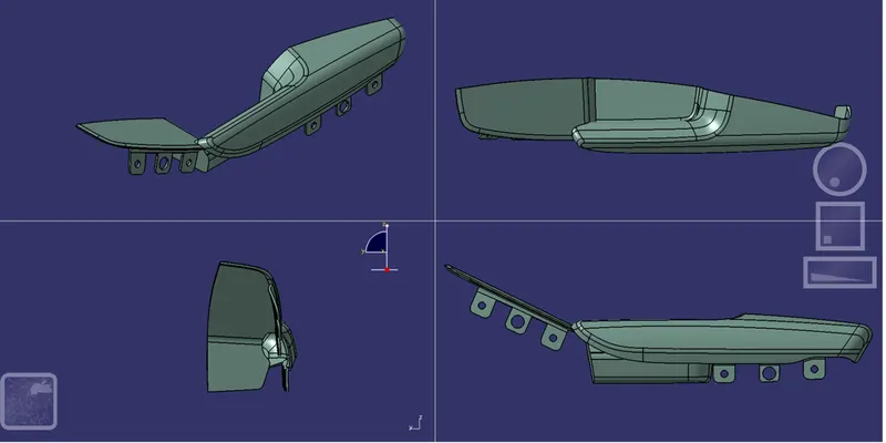
Armrest final component
MAP POCKET
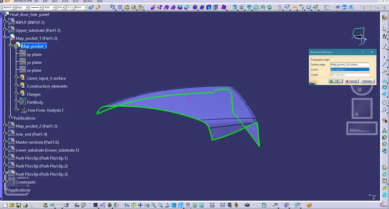
Surface check
To find out whether, if any gaps exist between the given A surface the boundary command has been used.
Tooling axis
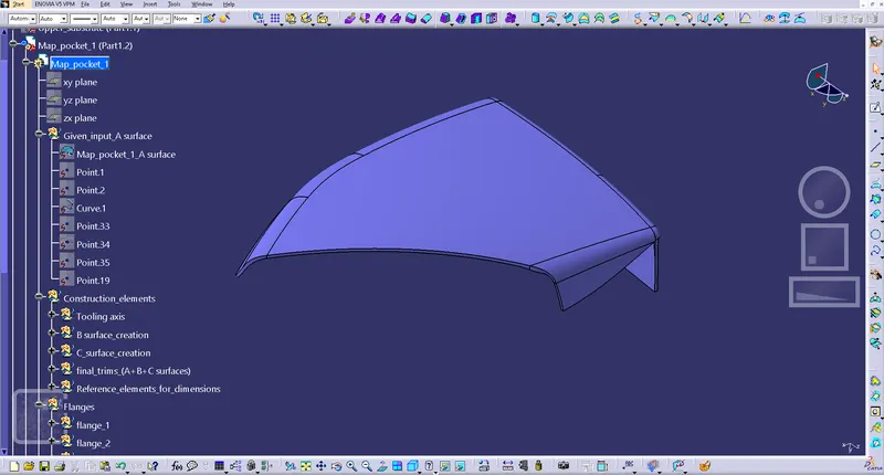
Here for the given component, the universal direction Y is taken as the tooling axis
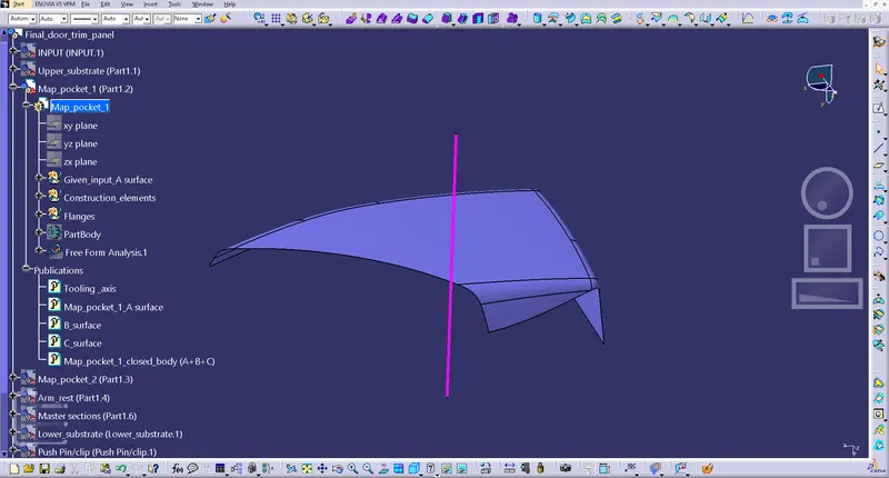
Draft analysis on the given class A along tooling axis
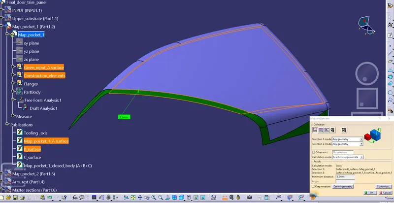
Class B surface
The thickness of the component is 2.5mm. Considering this the B surface is created maintaining an offset of 2.5mm from the A surface.
Class C surface
Creation of solid body using above all surfaces
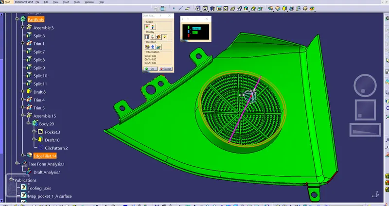
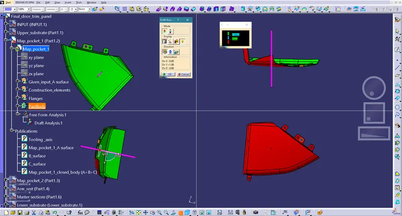
Final draft analysis on map pocket
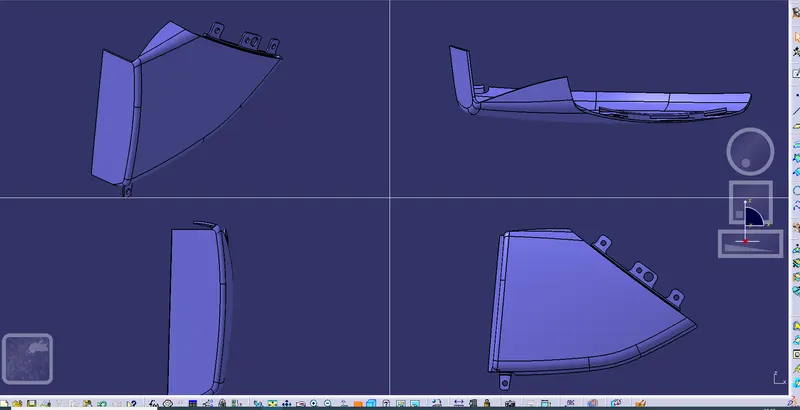
Map pocket final component
Bottle holder
Surface check
To find out whether, if any gaps exist between the given A surface the boundary command has been used.
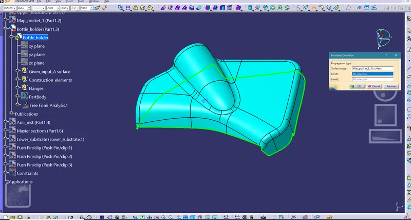
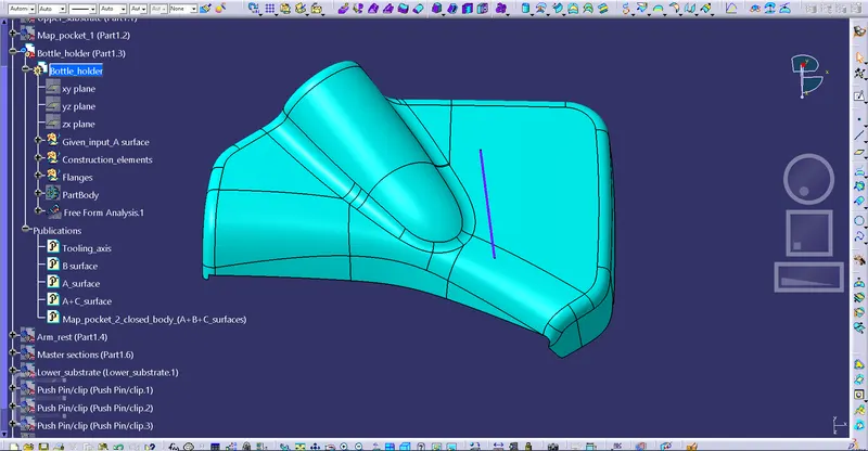
Tooling axis
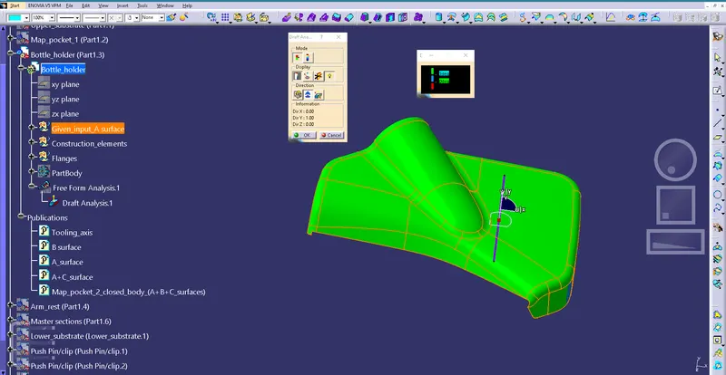
Here for the given component, the universal direction Y is taken as the tooling axis
Draft analysis on the given class A along tooling axis
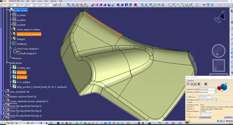
Class B surface
The thickness of the component is 2.5mm. Considering this the B surface is created maintaining an offset of 2.5mm from the A surface.
Class C surface
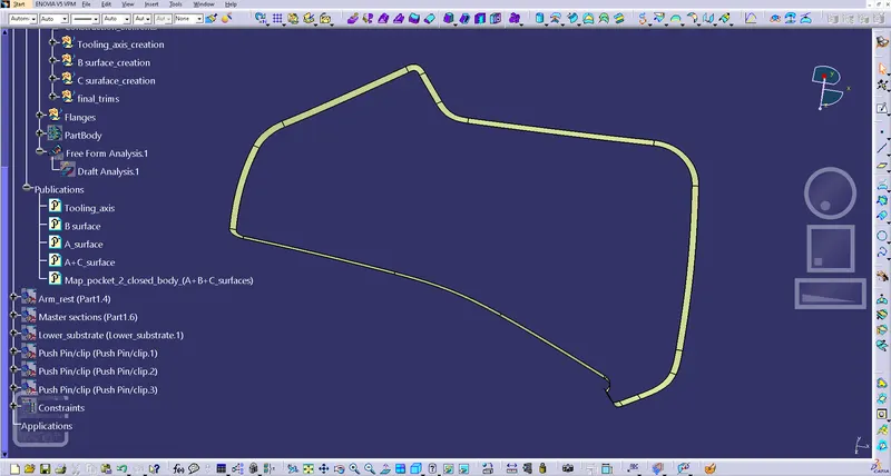
Creation of solid body using above all surfaces
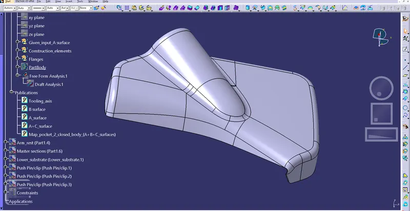
Adding engineering features
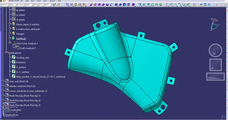
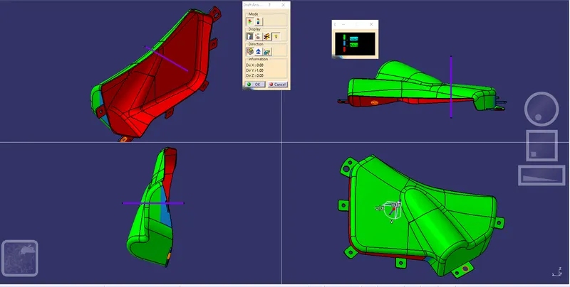
Final draft analysis on the bottle holder
In the final draft analysis, a few areas are not clearing with the given tooling direction. This is because of the problem within the given A surface. Since there is no class A designer the product design is continued without modification to the class A surface
Bottle holder final component
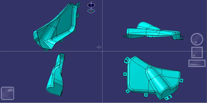
Lower substrate
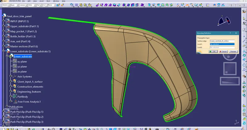
Surface check
To find out whether, if any gaps exist between the given A surface the boundary command has been used
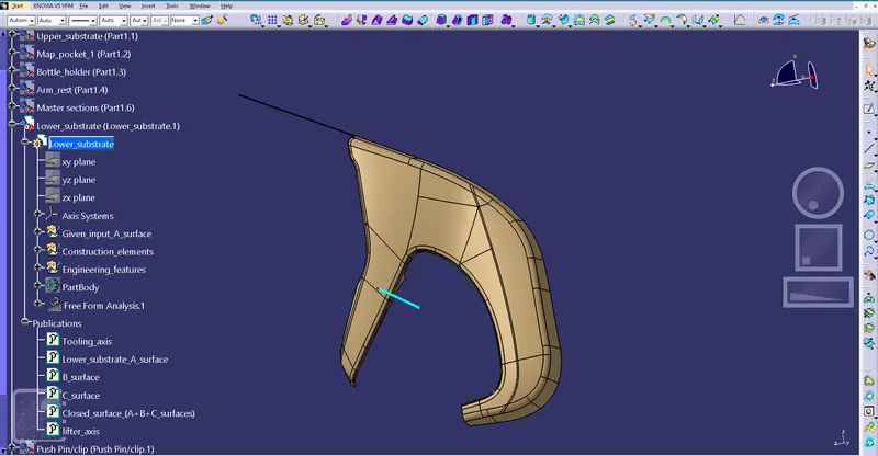
Tooling axis
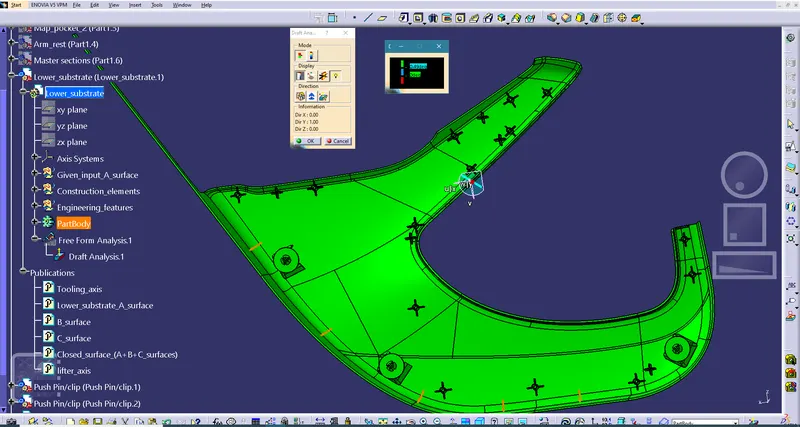
Here for the given component, the universal direction Y is taken as the tooling axis
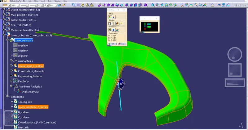
Draft analysis on the given class A along tooling axis
Class B surface
The thickness of the component is 2.5mm. Considering this the B surface is created maintaining an offset of 2.5mm from the A surface.
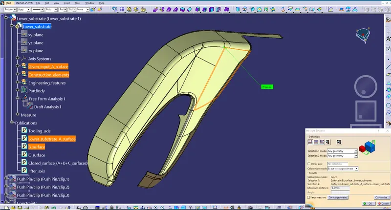
Class C surface
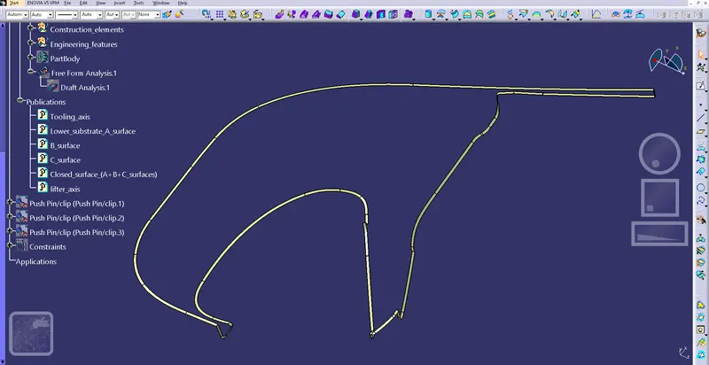
Creation of solid body using above all surfaces
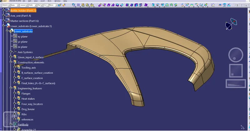
Adding engineering features
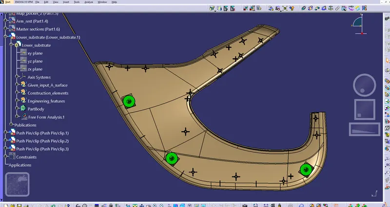
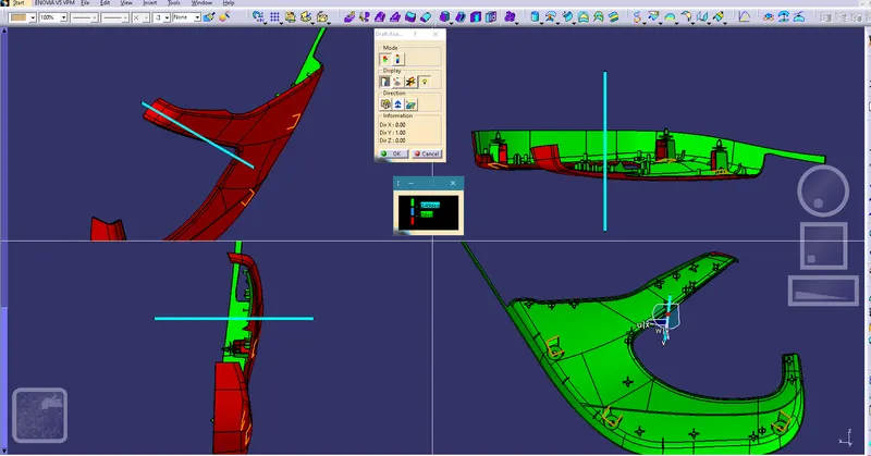
Final draft analysis on the Lower substrate
for this component, the draft analysis is performed at 0.49 deg. Although for the component a 3 deg draft is given. This is because few engineering features ribs have given a minimum draft of 0.5 deg.
Draft analysis on dog house using lifter axis
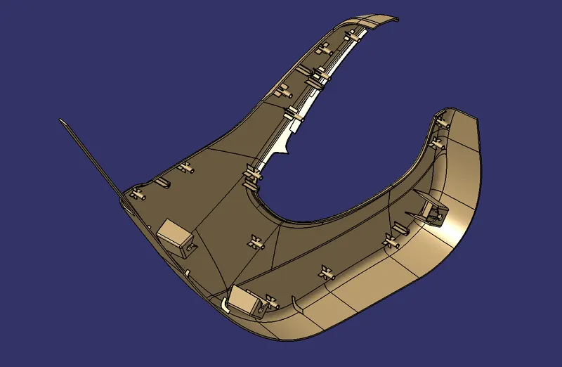
Lower substrate final component
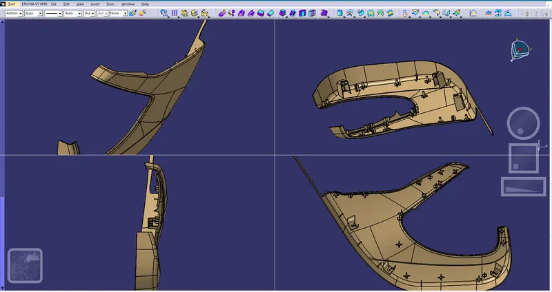
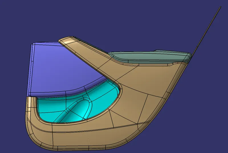
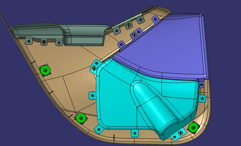
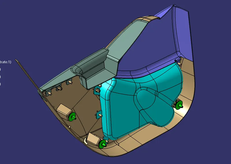
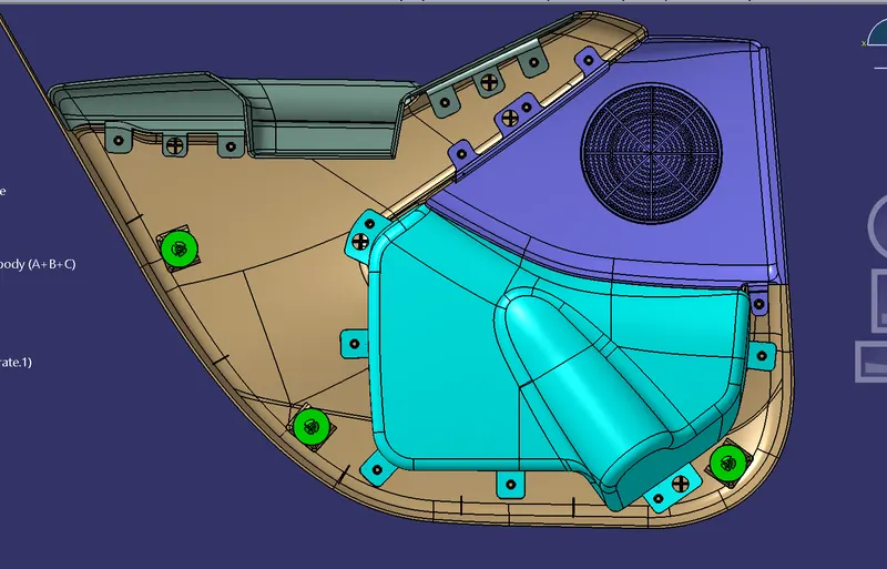
Final assembly of all components