Week 11 - Final project
Aim:- The Aim of the project is to develop car door trim using Catia V5 with given class A surface and also create B side features using the design rules.
Objective:-
- To create a tooling axis on the class A surface so that we can perform the draft analysis on class A surface and the solid part.
- To create the class B and class C surface using the class A surface.
- To get the final solid closed body from all the surfaces.
- To create the B side feature attachment for the solid body using the design rules.
Given Input:-
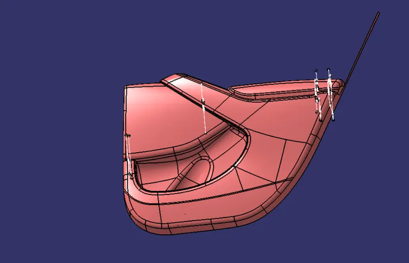
Introduction:-
Door Trim. An interior component attached to the inner side of the door. This product does more than merely improve the appearance of the vehicle interior. Rather, it is a vital module component that creates a more comfortable interior by providing a variety of accouterments and functions.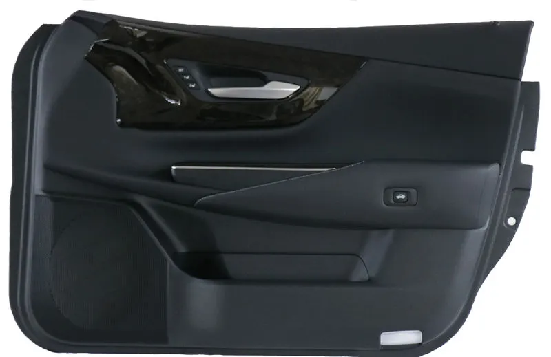
The materials like Acrylonitrile butadiene styrene,Polyvinyl chloride,Polypropylene and polycarbonate this are the some of the materials that are used in the manufacturing of car door trims.
Steps for developing the car Door Trim:-
- First we divide the given input into four different parts Lower substrate, Map pocket , Bottle holder and Door arm rest.
- Next we create the Tooling axis for the each individual parts.
- Perform Draft analysis on each part.
- Creation of class B and Class c surface.
- Join all the surfaces together.
- We get closed surface body convert that body into solid.
- Next we create the flanges for the solid bodies.
- Create B side features for the body.
- perform draft analysis on solid body and B side attachments.
Procedure:-
Creation of Tooling axis
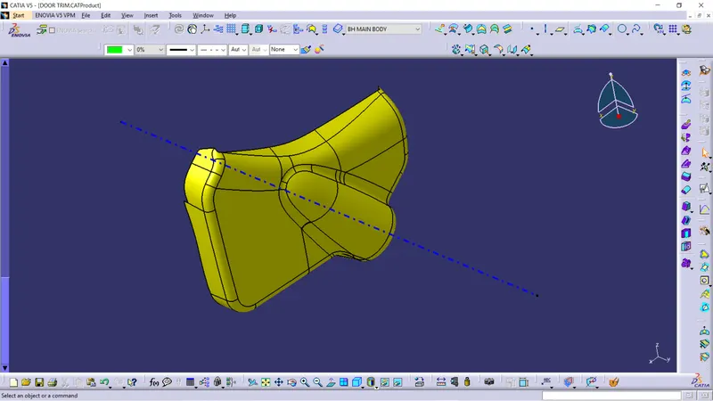
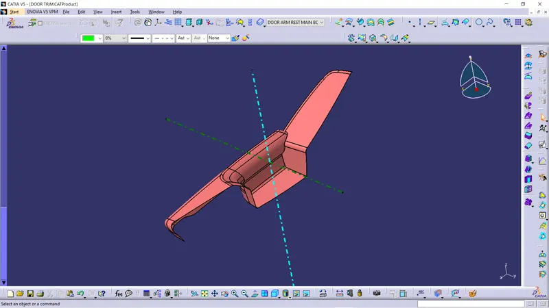
The Tooling axis is the direction in which the core and cavity will get open and close. Their are different types of methods to find tooling axis here we are using same method for all the different parts the method is we put a point on the surface and drawn the line through the point to y direction.
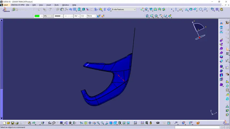
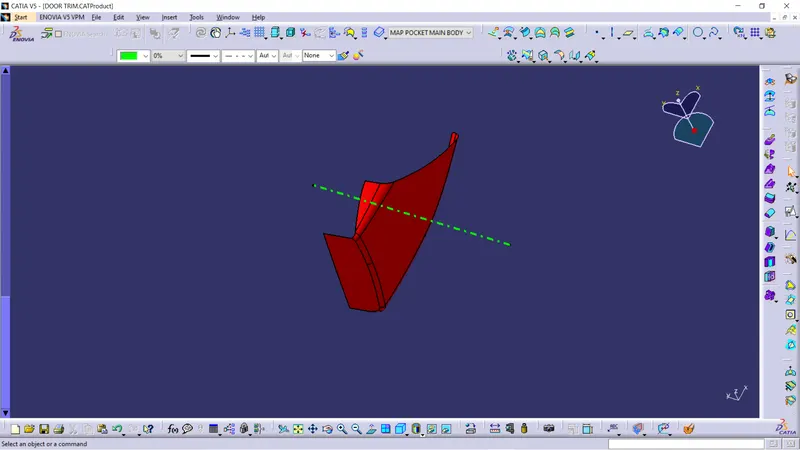
Creation of B surface
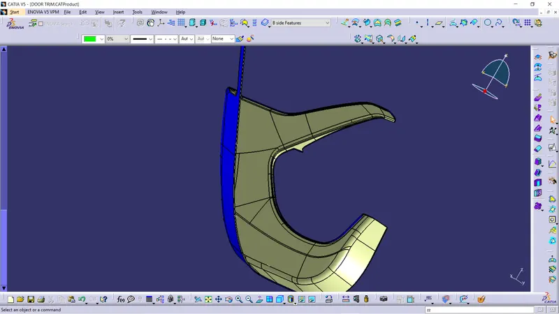
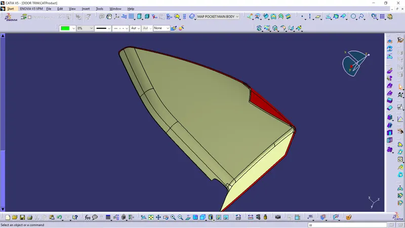
In creation of B surface we just offsetted the class A surface to 2.5mm (From master section) and when the Class A surface is offset some of the areas of the surface will get miss and we should work on that missing surface and recreate that surface and this is process we done for all the different surfaces.
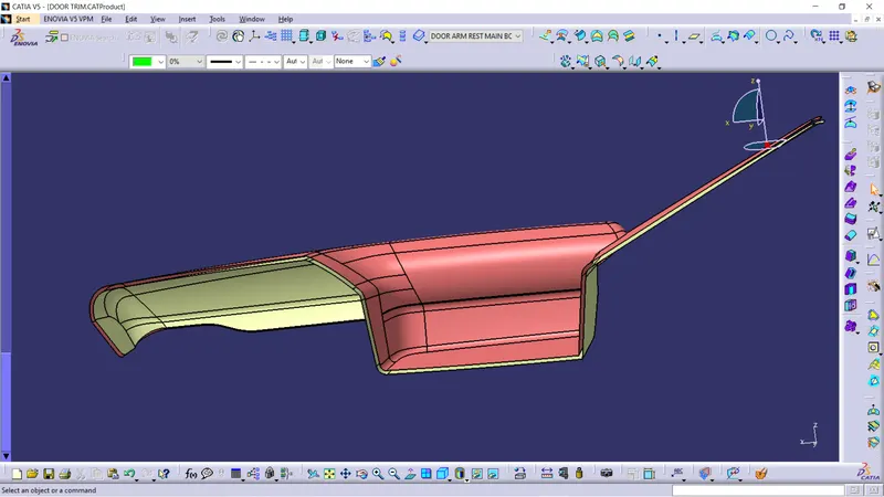
Creation of C surface
In creation of C surface we extracted the boundary of Class A surface and make it into smooth curve and we sweep the curve at angle of 90 degree to the reference surface and at an angle of 3 degree with tooling direction we done the sweep according to our requirements. we have done same type of approach for the different parts.
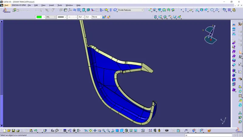
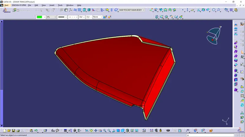
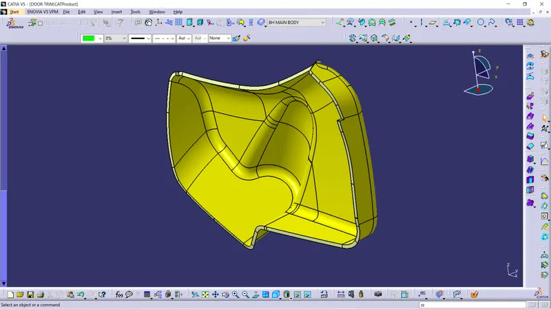
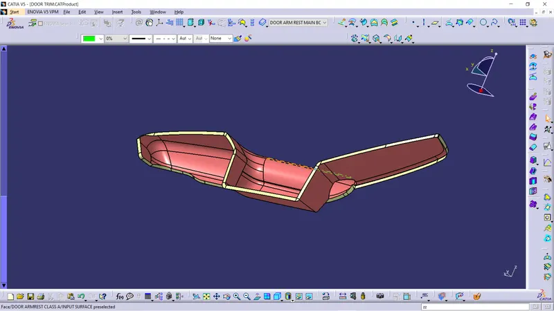
Creation of final closed body
In creation of final closed body we trim and join the class A , class B and Class c surfaces together
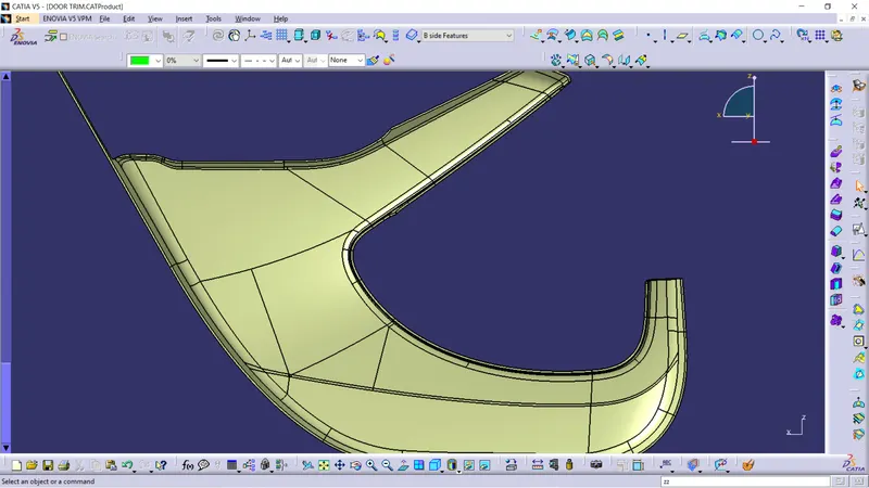
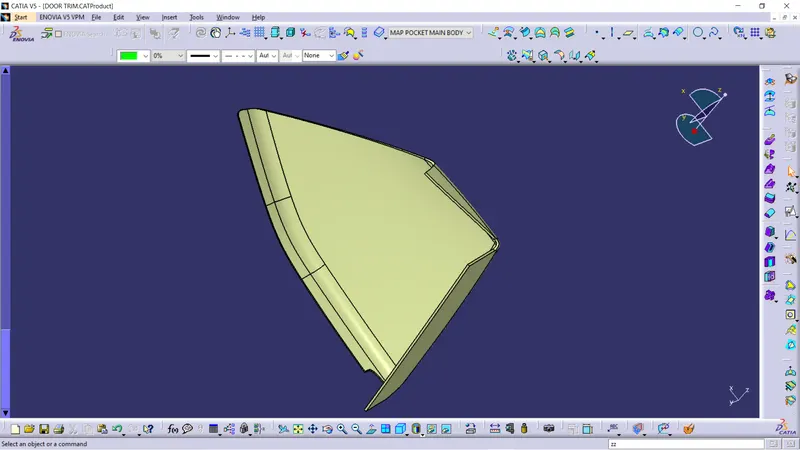
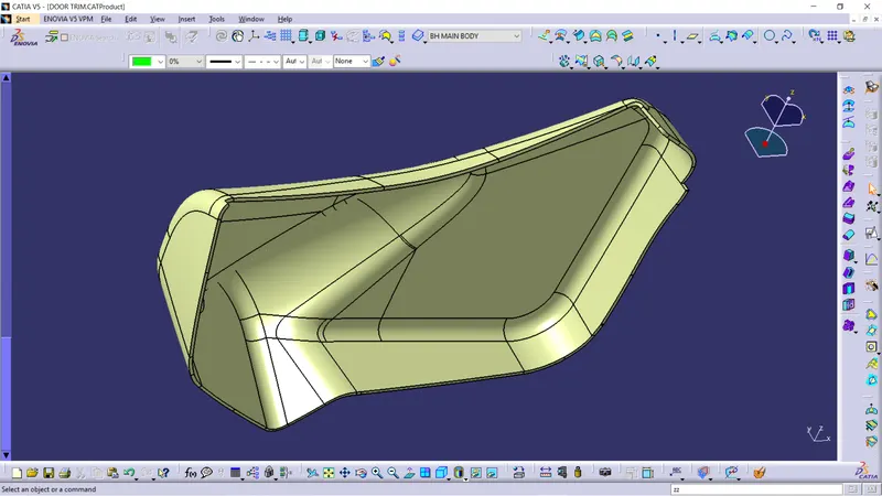
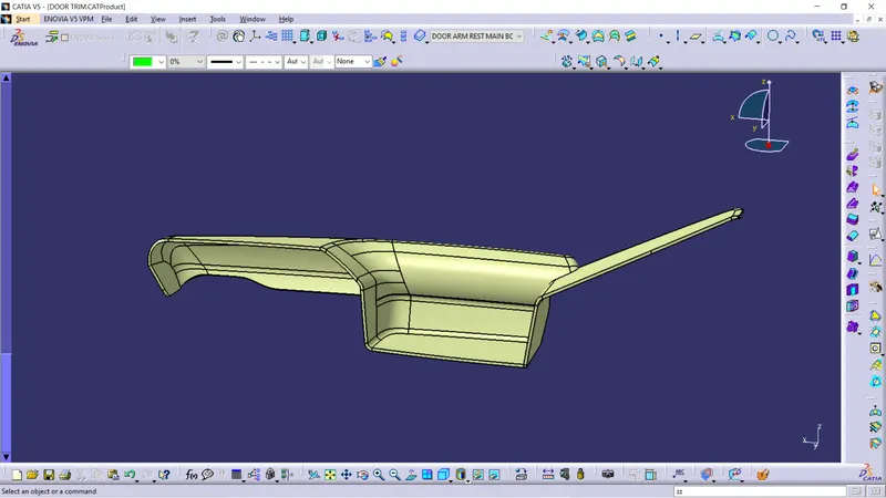
After creation of closed body we covert them in solid body and we add flanges and B side features for the parts.
creation of flanges
Flanges are the extentions of the solid body that are used to join one another parts . The flanges are created by following the master section.
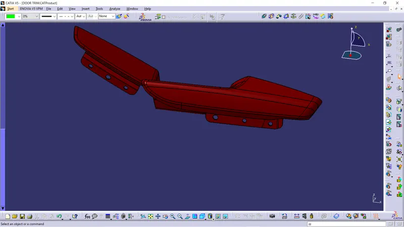
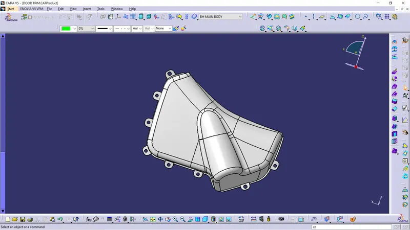
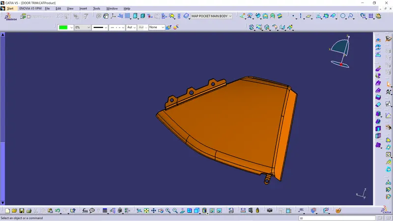
B side features:-
Ribs
Ribs are created on the B side of the body and the main purpose of the ribs is used to provide the additional strength and support for a part.
Design rules for ribs are
- Thickness(t) = 2.5mm
- Rib draft = 0.5degree
- Rib fillet radius = 0.25mm
- Rib thickness =0.4*2.5=1mm
- Rib Height =0.5*2.5=12.5mm
Dog House
Dog house are created on the B side of the body and the main purpose of the Dog house are to prevent the sinkmarks on the surface and other engineering features and placed on the surface of dog house.
Design rules for Dog House are
- Doghouse wall thickness at the intersection of the part wall ( C ) should be 40% or less than the main wall stock ( T ).
- Height of ( B ) should be between 3.0 – 6.0 mm
- Minimum draft should be 1.5 degree.
- Minimum width should be 12mm.
Heat Stakes
Heat Stakes are created on the B side of the body and the main purpose of the Heat Stakes are used as attachment feature for the adjacent component by the process of heat staking.
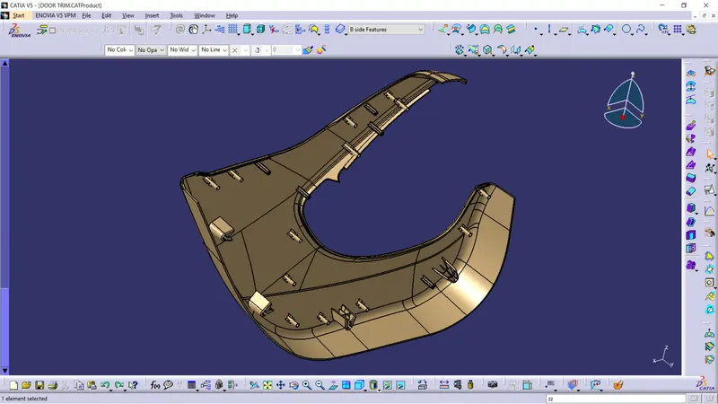
Draft analysis on Final solid Body:-
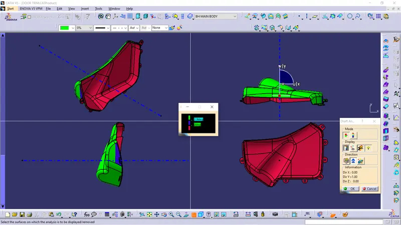
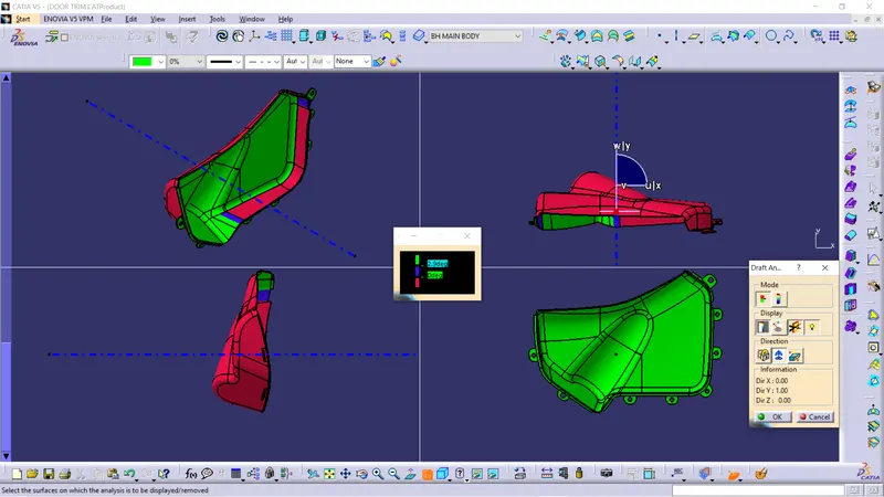
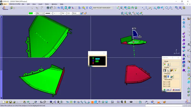
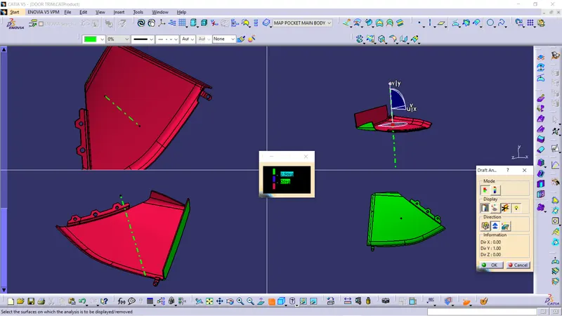
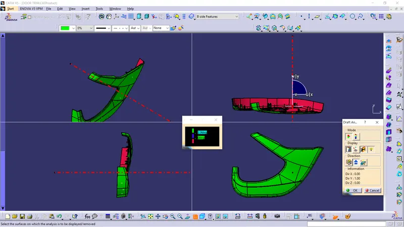
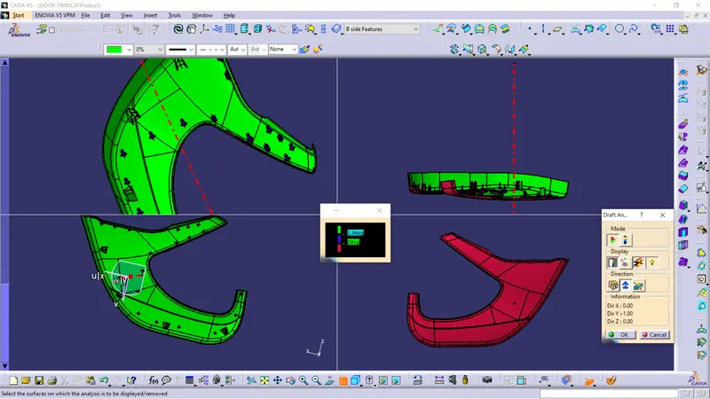
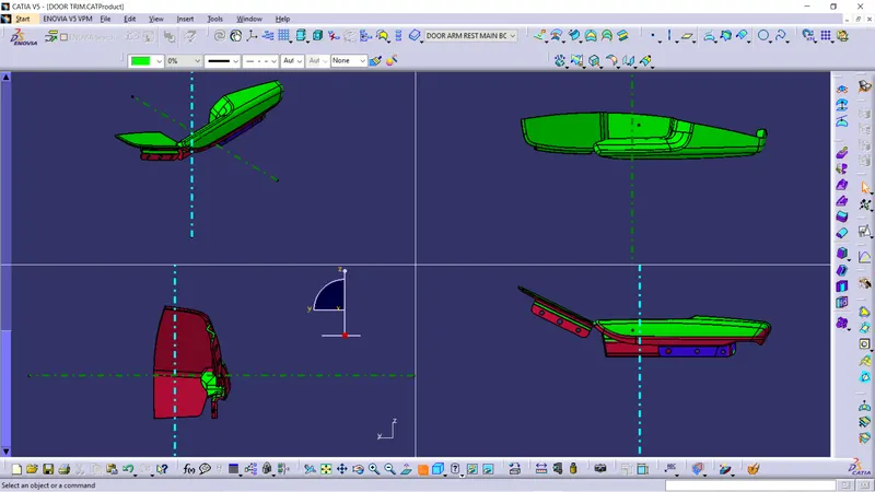
- Draft analysis was performend on the solid enclosed body along the tooling axis to analyse if the given component is toolabe along the tooling dircetion.
- Feature draft analysis option is used to perform the draft analysis on the solid enclosed body.
- Compass is placed on the created tooling axis using the option in draft analysis ,next the solid enclosed body is chosen to perform the draft analysis.
- We take maximum of 2.9 degree of draft angle for the surface.
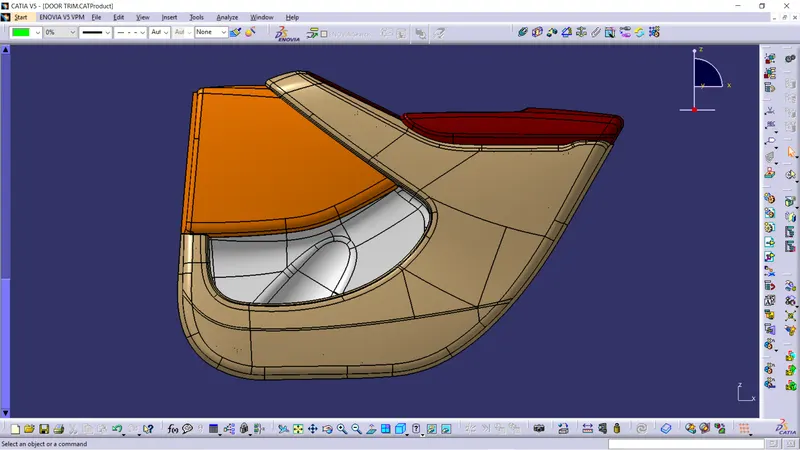
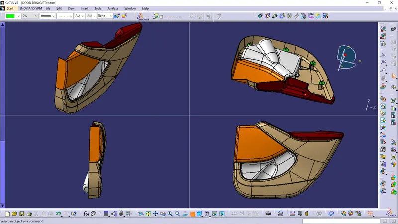
Final output of Door Trim:-

Conclusion:-
Hence the given Class A surfaces and master section are converted to plastic component and the required B side features are attached to the plastic component and the draft analysis is performed.