Week 11 - Final project
DESIGN OF VEHICLE DOOR TRIM PLANE
AIM:
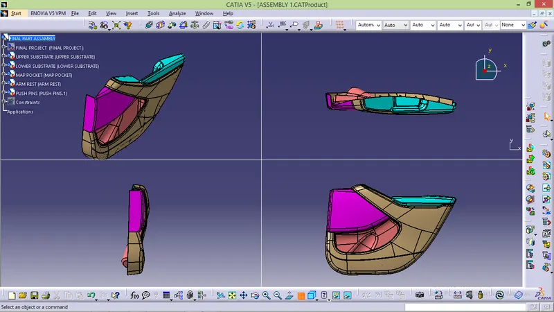
To create a solid body of side door including engineering features by using given class A surface and master section.
SOFTWARE USED: CATIA V5
INDRODUCTION:
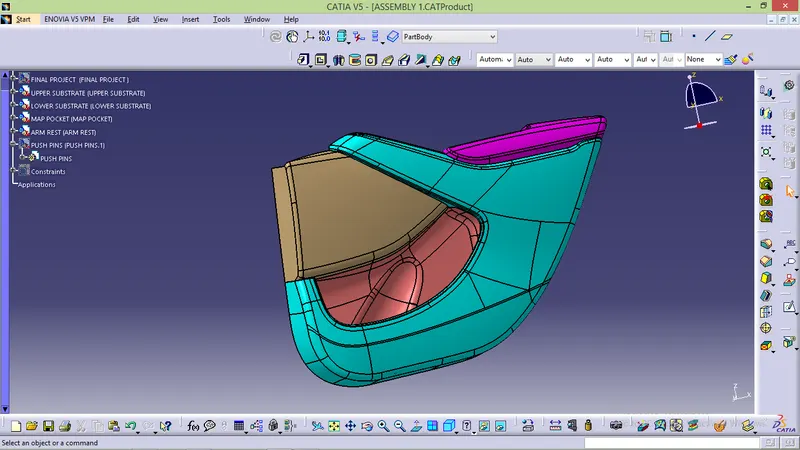
By using class A and mastersection we going to create calss B,class c.In this present article we going to see complete automotive product life cycle and how new prooduct design is done . In OEM and tier 1 companies they first draw concept sketch and developed through class A team then comes to feasibility check moves to concept validation then to new product design.In this report we going to see complete detail report about door trim the class A divided into four majoir parts they are.
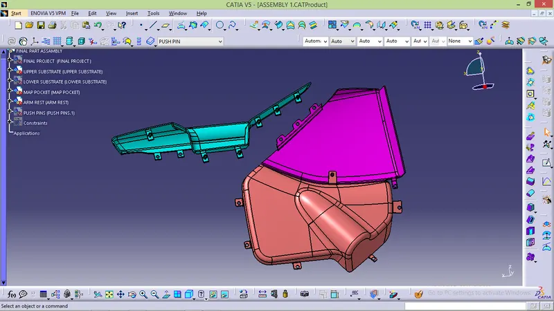
- Upper substrate
- Lower substrate
- Map pocket
- Arm rest.
PRODUCT LIFE CYCLE:

- Concept sketch
- Styling class A
- Feasibility check
- Concept validation
- New product design
- Development
- Proto built
- Design valitation
- Pilot production
- Mass production.
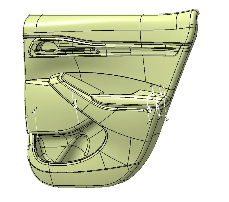
MASTER SECTION: mastersection are the guide for design requirement which decide the component packaging after technical class A surface.
ATTACHEMENT:
- Dog house
- Ribs
- Heate streakes
- Flanges.
CLASS A SURFCE:
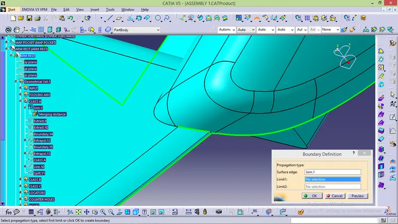
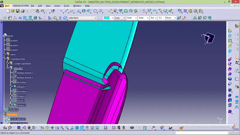
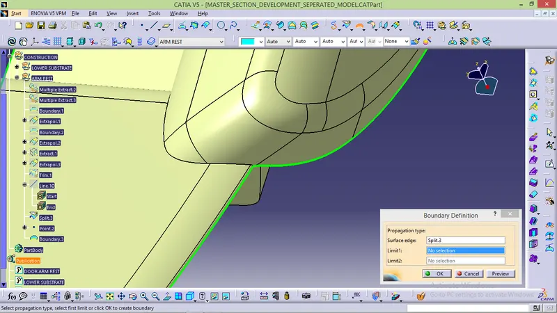
- By using boundary or joint tool check class A to confirm there is no gap or patches .If u find any gap or patches infrom class A developer and after getting permission correct the patches and then start development.
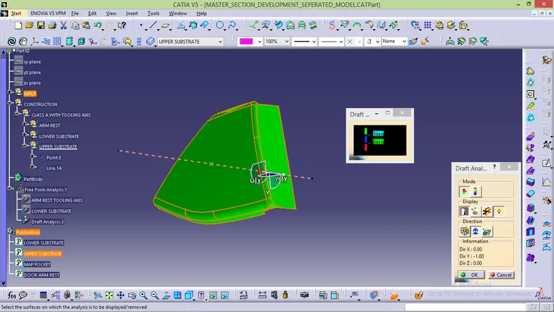
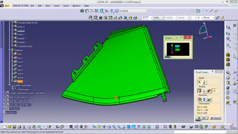
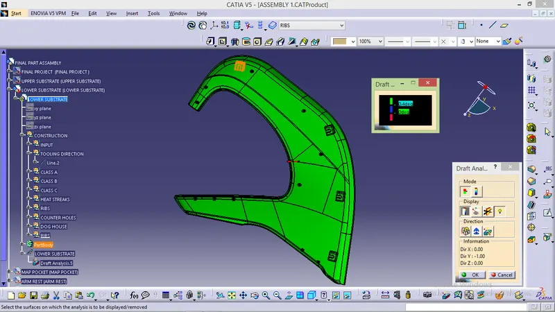
TOOLING DIRECTION AND DRAFT ANALYSIS FOR INDIVIDUAL CLASS A:
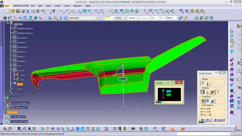
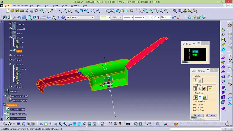
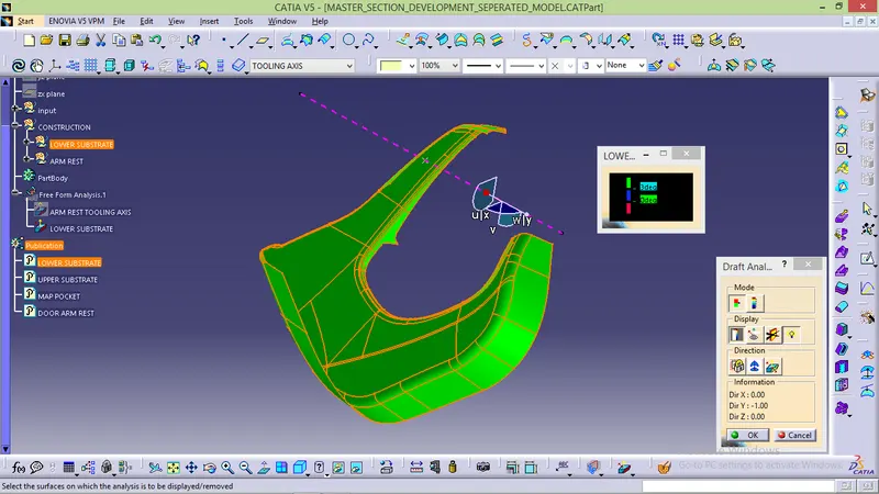
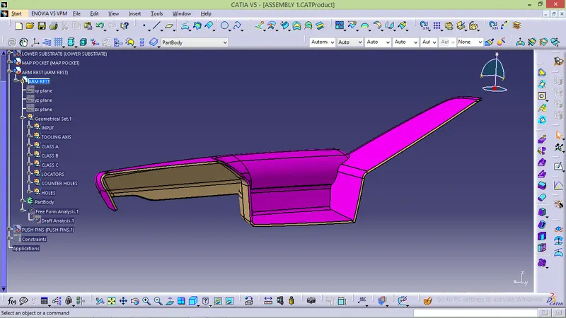
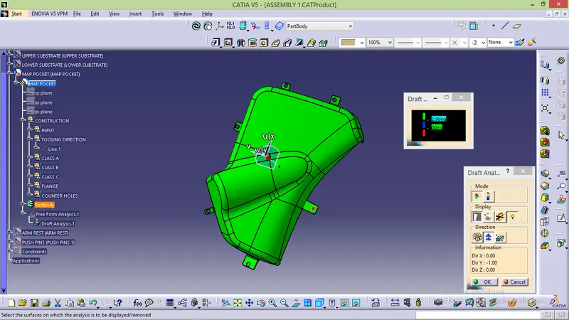
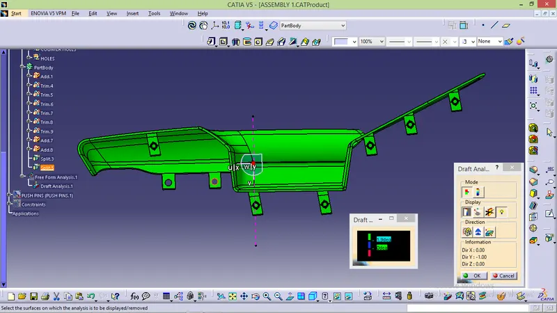
- All parts are satisifed along Y tooling direction except door arm rest for that we need to create slider axis because it not satisfied along Y tooling direction so that we need to create slider axis.
CLASS B SURFACE CREATION:
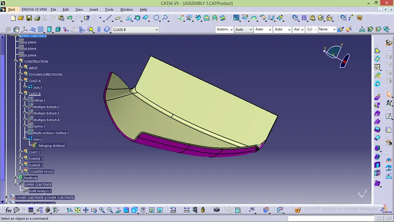
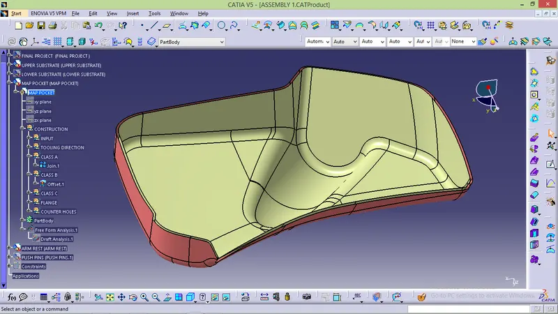
- Class B are created by offset from class A surface to 2.5mm (2.5mm is conform by measured in mastersection)
- After extrate if need any split or MSS created it
- main thing is class B project same as class A.
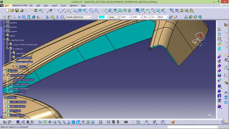
CLASS C SURFACE CREATION:
- Class c surface create by using swwep tool with respect to the surface and tooling direction
- By using sweep tool select guide cure and reference surface and sweep along tooling direction
- Some boundary can't be sweep and that area use MSS,spline line and blend tool to create along surface
- After C surface created join it properly.
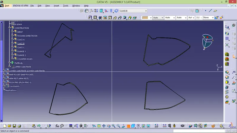
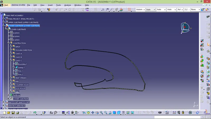
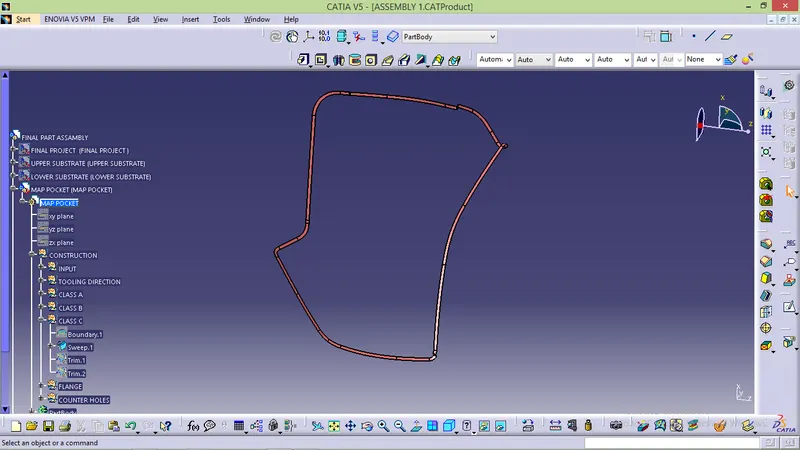
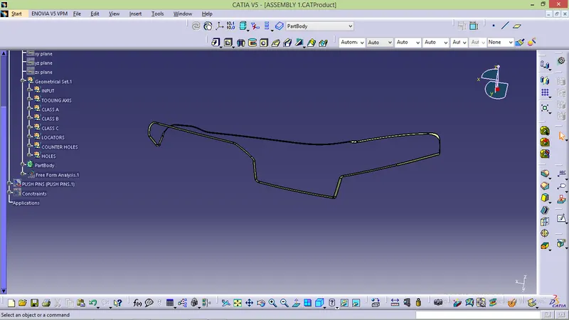
JOINT CLASS A,C AND TRIM WITH CLASS B:
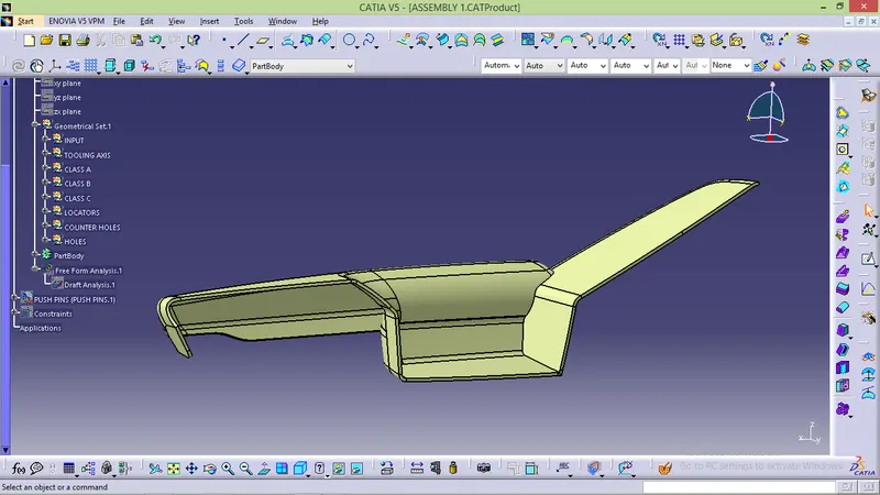
ARM REST
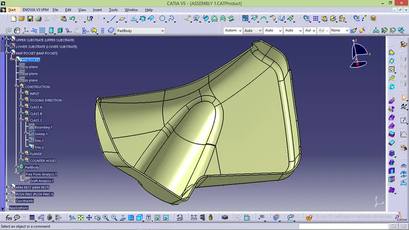
MAP POCKET
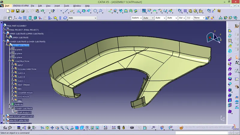
LOWER SUBSTRATE
UPPER SUBSTRATE
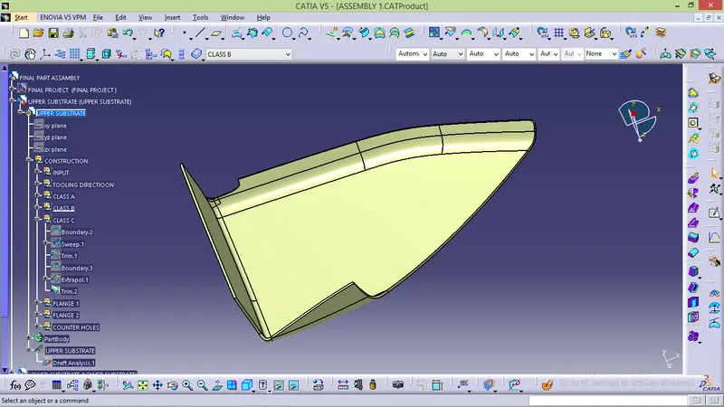
CLOSED BODY:
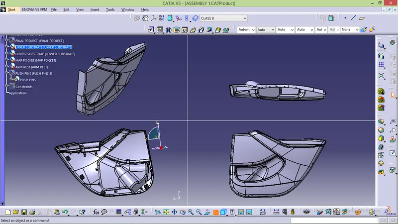
B SIDE FEATURE CREATION:
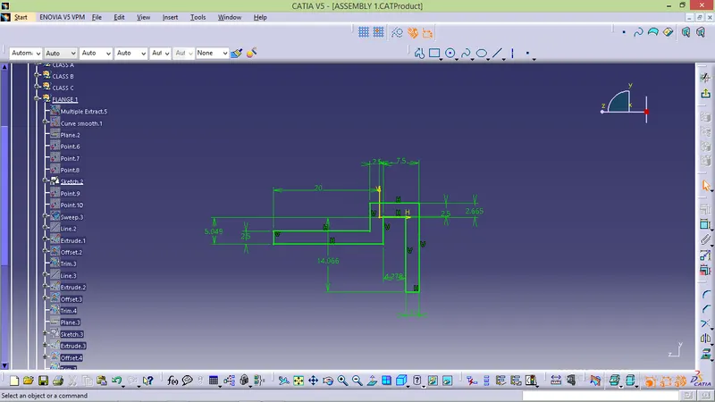
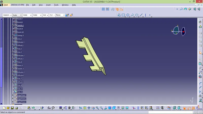
FLANGE CREATION
- Flange is used to hold component
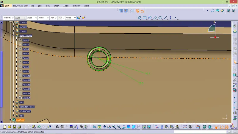
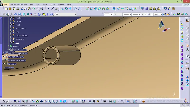
HEAT STREAKES:
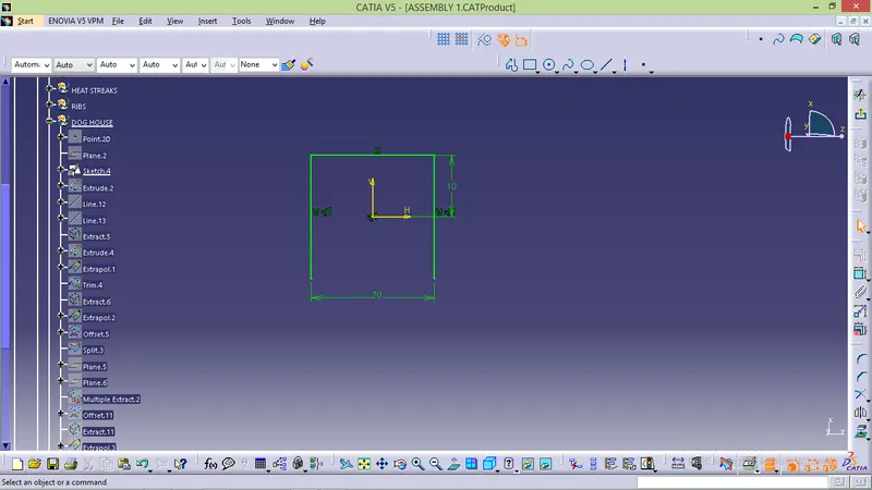
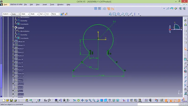
DOG HOUSE:
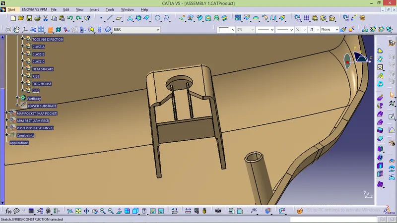
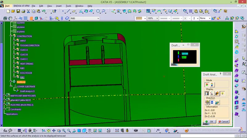
COUNTER HOLES:
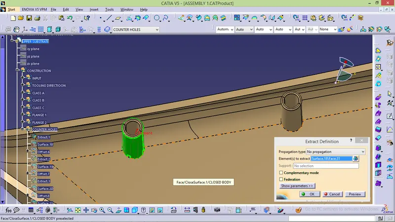
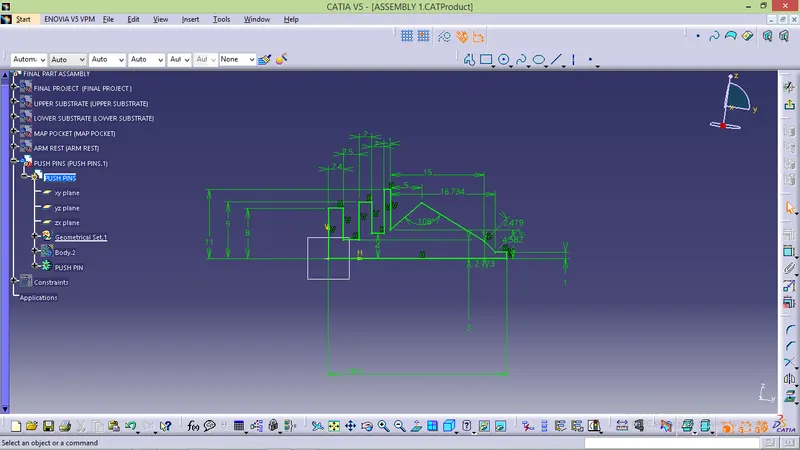
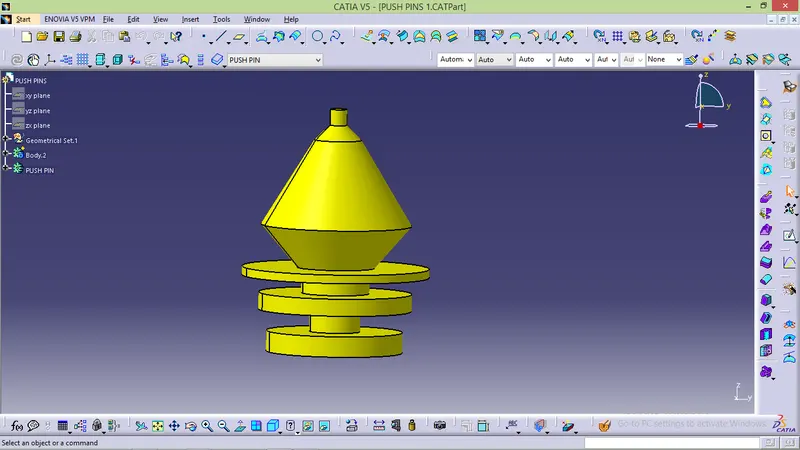
PUSH PIN:
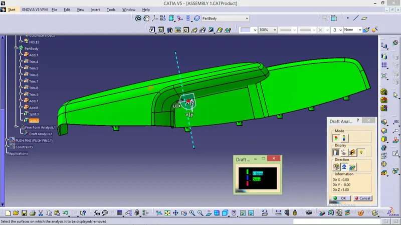
DRAFT ANALYSIS:
FINAL PART:
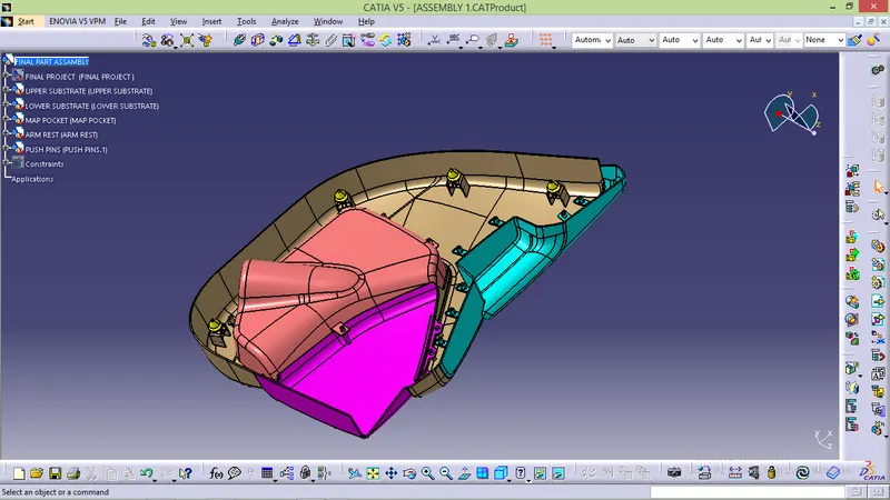
COCLUSION:
- Class A,B and C surface created as per automotive standards
- B side feature created as per design rules for heat streakes,ribs,locators and dog house
- Draft analyis was performed for all component.