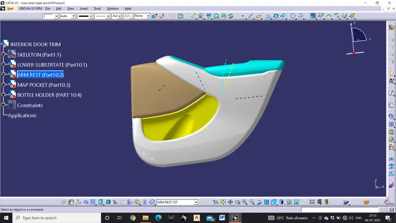
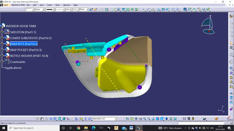
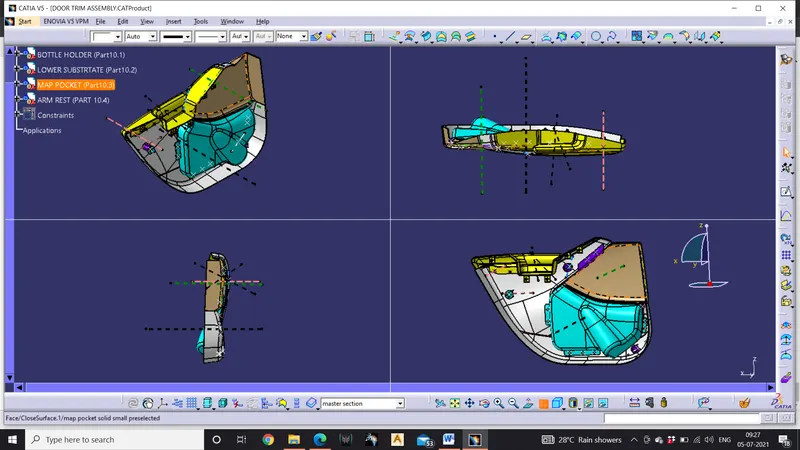
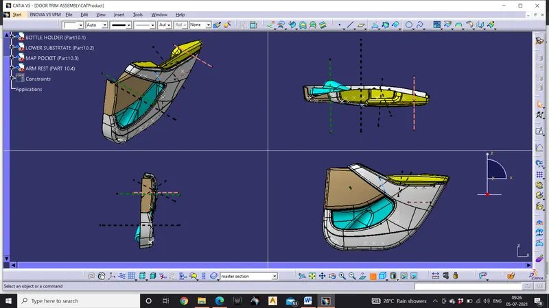
DESIGN OF INTERIOR DOOR TRIM USING CATIA V5
AIM: to create a solid model of interior door trim and B side features using given class A input using CATIA
Tools used:
Line ,point, circle, extract, multiple extract ,trim ,split ,join ,fill, multi section surface, parallel curve, pad ,Boolean operations ,fillet ,chamfer ,feature draft analysis, extrude , offset,sweep,etc.
Procedure:
Correction of class A surfaces
- Divide the class A into 4 small components
- Arm rest
- Map pocket
- Bottle holder
- Lower substrate
- Insert each of the component into new product in assembly workbench
- Work on the each component individually using given class A by creating class B and C surfaces
- Extract the class A and join the surfaces with maximum merging distance of 0.003 mm
- Check for boundary, correct the surface if any error occurs
Tooling axis and slider creation
- Extract the surface from the class A and create a point on the surface
- Create a line normal to the surface
- Perform draft analysis to find the tooling axis for each of the component
- Tooling axis must be adjusted to get the draft angle corrected.
- Nominal draft is 3 degree.
- Take reference from master section and create intersection and create a intersecting line
- Some parts cannot be tooled in main tooling axis ,for such parts a slider must be introduced
- To create a slider axis extract the surface from class A and then crate a line then perform draft analysis and then correct the compass orientation and lock the compass orientation
- Now give the direction for the line as compass direction and reset the compass.
- If tooling feasibility matches the required criteria then start creating B surface
- Now offset the class A to 2.5mm referred from the master section to get B surface
- Extrapolate the B surface
- Extract the boundary of the class A to create the C surface
- Divide the boundary of the class A to many small parts to easily create the C surface
- Use sweep command with reference to surface at 90 degree to get the C surface
- Finally extrapolate all the swept surfaces and make a trim to create a single piece
- Now join the class C to class A
- Trim the extrapolated B surface with the class A and C join to get the final trim
- Check for the boundary
- Sometimes the trim may not work due some projections occur while extrapolating the surfaces individually
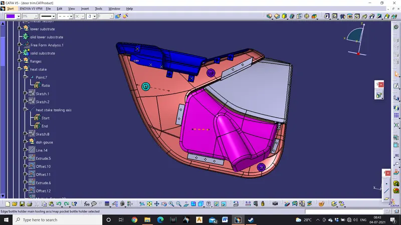
- Create the flanges for the solid components taking reference from master section
- To avoid this problem check for boundary and see that the boundary is clear
- Now open part workbench and use CLOSE BODY to get the solid component
- Following above steps all the components are made as solid body.
Creation of B side features using master section:
- B side features are used to attach the door trim to the door panel and joined by plastic welding the heat stakes ,B ide features include
- Dog house
- Push pins
- Heat stakes
- Screw bosses
- flanges
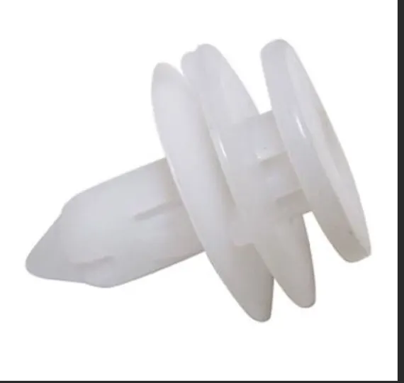
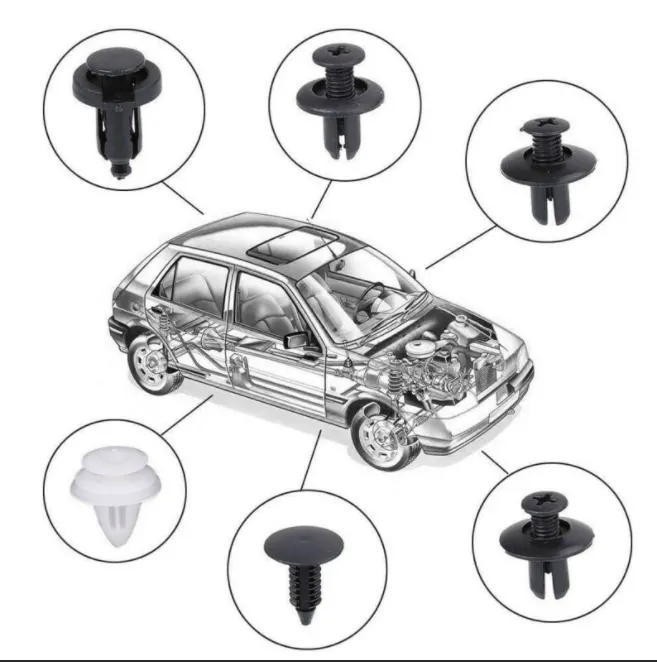
- Using 3-2-1 principle the attachment strategy should be decided
- The doghouse with push pin should be placed at strategic places where the translation along all the axis is constrained after plastic welding
- There are specific set of guidelines and design rules to create the B side features in automotive industry
- Major portion is occupied by the lower substrate so the remaining components are mounted to the lower substrate and then attatched to the door panel through plastic welding of heat stakes
- To create dog use positioned sketch and draw a rectangle and make one edge as construction element
- Extrude the sketch normal to the surface
- Follow the given sketch of the dog house
- Create a mounting inside where the push clip sits inside the dog house
- To avoid sink marks in the class A the dog house bottom is reduced to 40% of the nominal thickness
- This allows the molten metal to flow slowly avoiding sink marks in the classs A
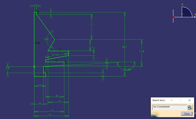
- Follow the sketch and make a push clip inside the dog house and assemble it to the dog house solid body
- To translate the dog house with pushclip extract the surfaces and create a point where the doghouses are needed on the lower substrate
- Add 0.5 degree draft to the iner walls of the doghouse
- Create a slider axis for the doghouse so that the inner parts of the doghouse can be tooled
- Create the screw bosses on the arm rest to attatch it to the door panel using screws
- To create screw boss a flange is required which is created from the master section reference
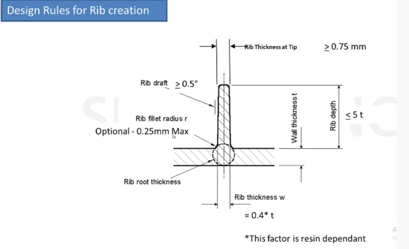
- The thickness of the screw boss should be 0.6 times the nominal thickness
- To support the screw boss ribs should be added to the screw boss
- Create a positioned sketch and then pad the sketch and union trim wit the screw boss solid body
- The screw boss with the ribs is prepared
- To translate the solid body extaract the surface from the flanges and create a parallel curve and create points on the curve
- Copy and paste special the solid body and translate the solid body where ever required on the lower substrate
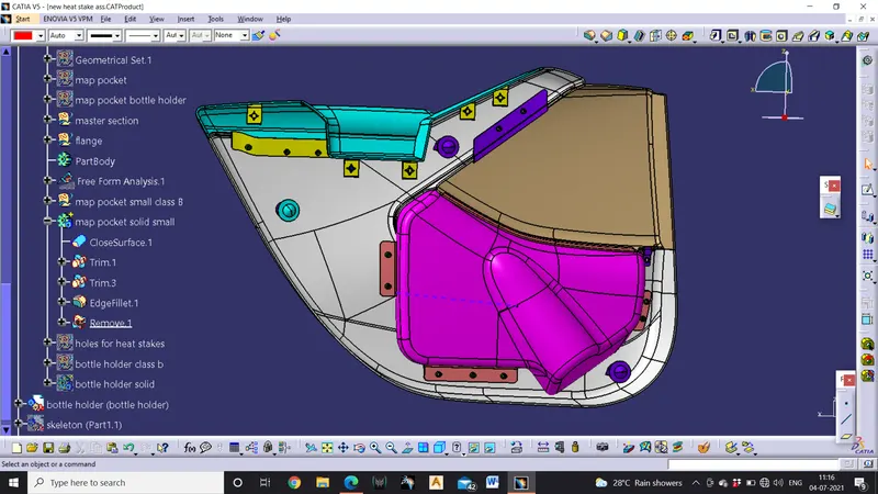
- To create holes on the flanges for the heat stakes
- Use the extract command and extract the points generated from the heat stakes
- Using that point create a positioned sketch with dia 1mm more than the heat stake dia
- This is done to give the clearance of 0.5 on either sides of the heat stake
- Pad the sketch and using same method to translate the heat stakes ,translate the pad where ever required
- Now using remove operation from Boolean operation remove the pad from the flanges
- Hence B side features for the given part are created
- Perform draft analysis for tooling feasibility.
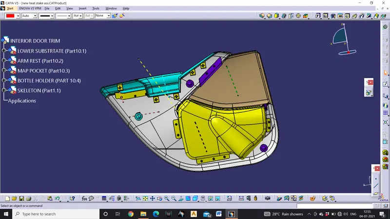
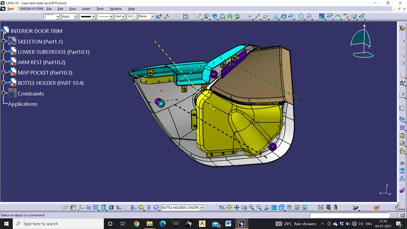
Assembling the products
- Create a skeleton and fix the product
- Now using coincide command coincide the point of the skeleton with the lower substrate main tooling axis
- Then coincide the points from the heat stakes and points from the holes created on the flanges
- Using contact coincide for the contact flanges
- Make sure that all the degree of freedom are arrested and make sure to update at every coincidence
- Finnaly apply material to the assembly
- Hece interior door trim with B side features is completed.
design rules for attatchment features
dog house design rules
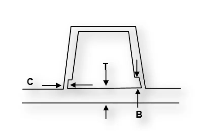
C should be 40% or less than the nominal wall thickness.
B should be ranging between 3-6mm
T is the nominal wall thickness
make sure that the dghouses are at a distance of 25mm from the wall
screw boss design rules
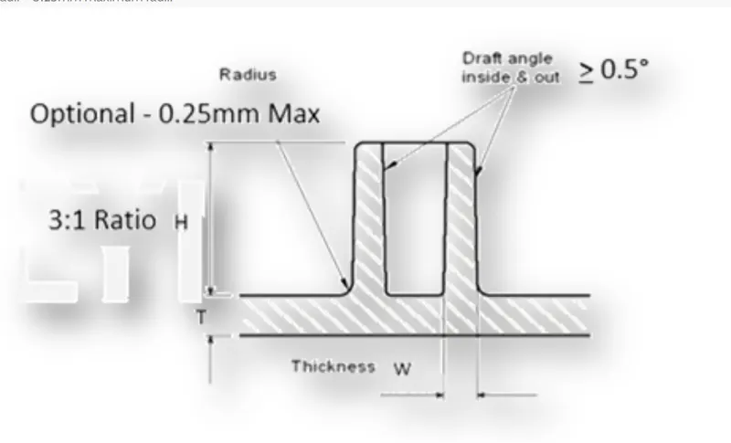
heat stake sketch
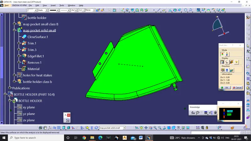
map pocket draft analysis
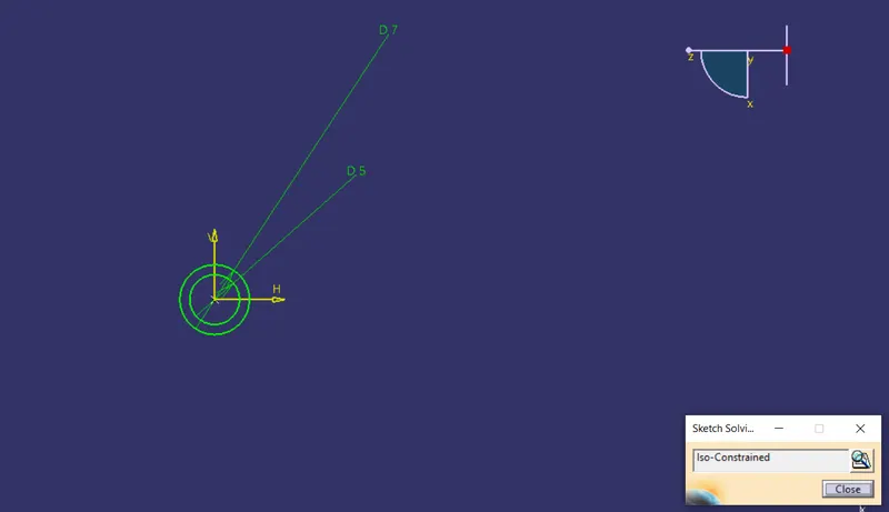
push pin sketch iso constarined
dog house with push pin mounteed on it draft anaysis using slider axis
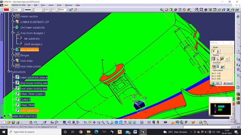
lower substarte draft analaysis
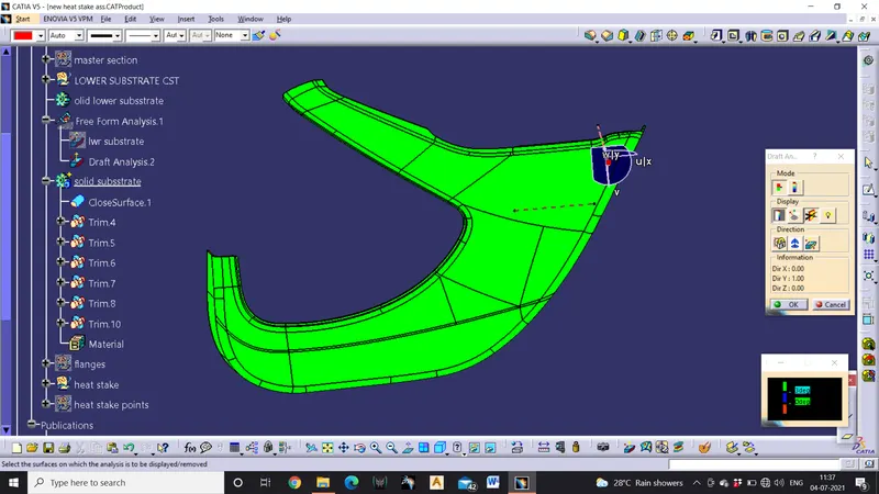
arm rest draft analysis
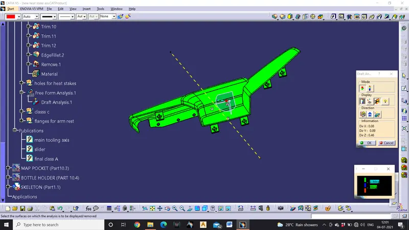
heat stake with draft analysis
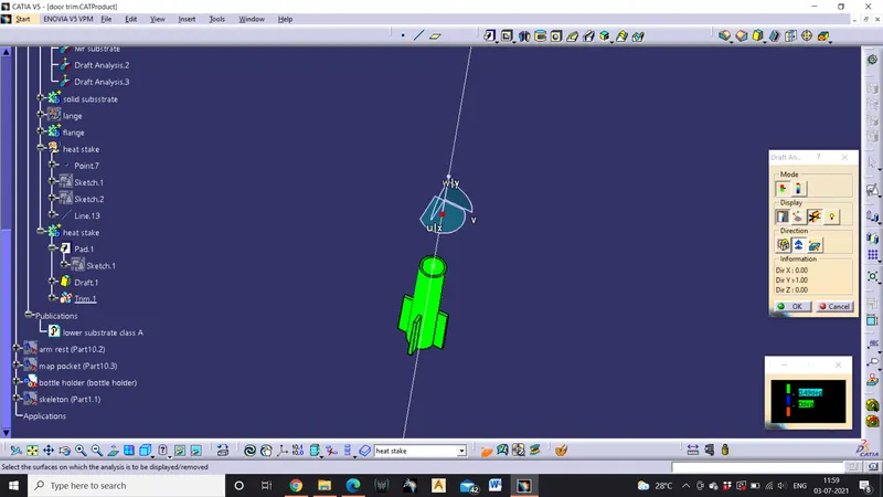
dog house attatchment
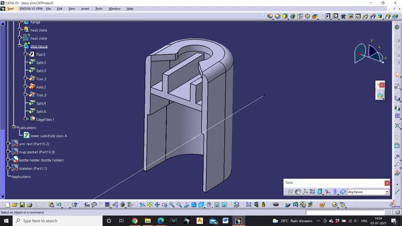
dog house draft analysis for inner part
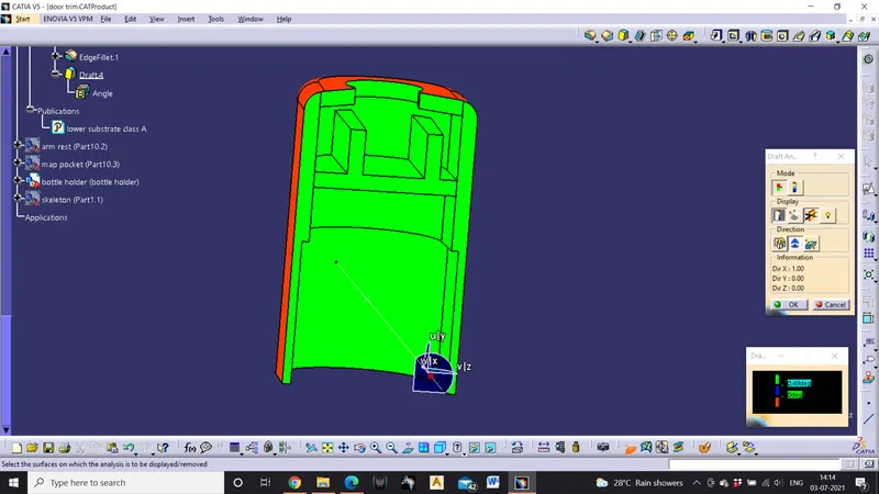
screw boss draft analysis with nominal draft of 0.5 degree
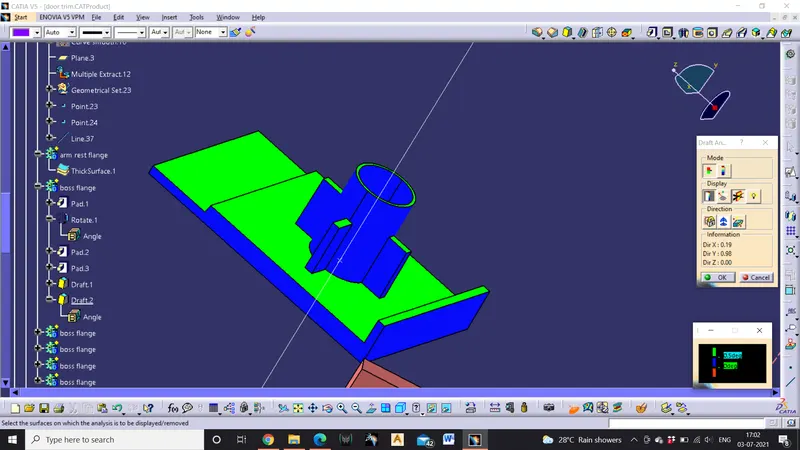
complete door trim assembly