Concept Modelling of Alloy Wheel using Autodesk Alias
Title of project: Concept modelling of alloy wheel.
Objective: To create surfaces of the entire alloy wheel.
Tools used:
Freeform blend tool, CV curves, line, circle, skin, align tool, planar, trim, project, intersect, extend, detach tool, transform tools etc.
Introduction:
Introduction to surface continuities and its types
Continuity is the smoothness of the junction i.e., two mating curves. Continuity is the condition that the more smoothly the adjoining surfaces flow
Generally there are 4 types of surface continuities i.e., we can have surfaces coming in contact in 4 different ways.
They are:
- G0-position (touching)
- G1- tangent (angle)
- G2-curvature (radius)
- G3-acceleration (rate of change of curvature).
- G0-position (touching) continuity:
This is less smooth type of joint with common end point. This position is the only condition to satisfy the joint.G0 is the point continuity when one curve touches the other and shares the same boundary
- G1- tangent (angle):
One can’t have G1 continuity unless you have G0 continuity.it is also called as second order of continuity i.e., to faces meet along a common edge at a tangent plane they share a common angle. The best example for G1 continuity is a fillet.
- G2-curvature (radius):
G2 adds another order that must match across our pair of curves. For G2 it must a tangent to the curve and have the same curvature a point where they touch I.e., the input geometry must now be curved s well so the input containing a straight line can’t make a G2 curvature.
- G3-acceleration (rate of change of curvature):
G3 continuity includes the concept of acceleration of the curvature; the amount of change in the curvature over the length of the curve.G3 is looking for balance on the rate of curvature.
Description:
- Open auto desk alias and choose class A surfacing.
- Import the canvas image by going to file > import canvas image > always create new layer.
- Align the image pivot point to the grid for ease of creating curves, to do that select the image and select set pivot point and align image to the grid.
- Divide a part from the wheel where the whole wheel reciprocates i.e., the pattern repeats itself.
- Start by tracing outlines of the wheel.
- Make a line at an angle by picking it > information window> attributes> rotate -45 degrees as per the requirement.
- Make a circle at the centre and outer edge of the wheel to form basic structure.
- Detach the circles at which the repeating pattern appears.
- To form a surface we need something to build on, so use “skin” command to form a surface.
- Draw small circle as the spoke surfaces are flowing inwards.
- Use CV curves, make a curve joining outer and inner circles and make a small straight line to make it G2.
- Now project the small straight lines on to the previously skinned surface.
- Now the curves will start moving. Adjust the curvature using explicit controles.
- Now assign all the curves to another layer as the cueves will creat problem.
- Create a blend using free form blend tool where the circles are detatched and extend both the sides where the spoke surfces are joing inwards.
- Using 2 generation 2 rail curves, create a surface of the pattern.
- The basic form of the pattern is now created, now through visualization the inner surfaces are created by projecting curves on to another surfaces.
- Make a circle and scale it upto to where it reaches the required dimentions.
- Using “planar” tool the circle is converted into a surface. Adjust the CV of the surface as per the shape of the wheel.
- Now again trace the curves from the wheel and project on the surface.
- using blend tool, blend the surfaces to create the required geometry.
- Now carefully create surfaces between the two surfaces choosing skin or rail or blend tools.
- Make sure every curve is aligned G2 using align tool from the objest edit.
- Now intersect the surfaces and trim the unwanted parts.
- Now create semitry of the surfaces and create geometry.
- To make holes for bolts, a circle is made and projected on the planer surface and trimed.
- Another circle is made to create depth for the bolt.
- To complete the wheel, the pattern developed should be revolved from a pivot point.
- To do that, select the object, go to edit>duplicate object and select the axis of revolving and enter the angle and number of spokes to be dublicated.
- The concept model of alloy wheel is completed.
Images:
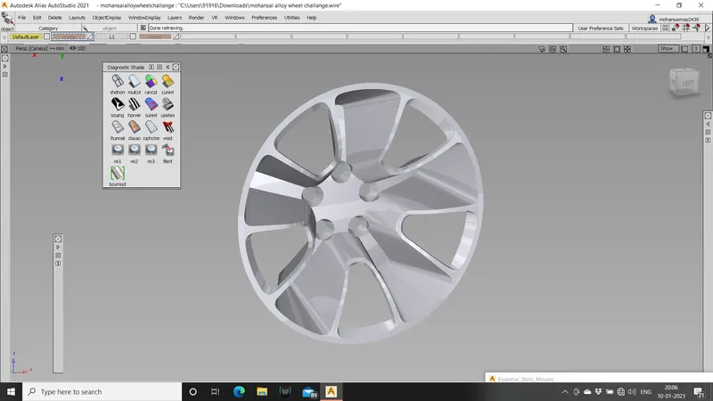
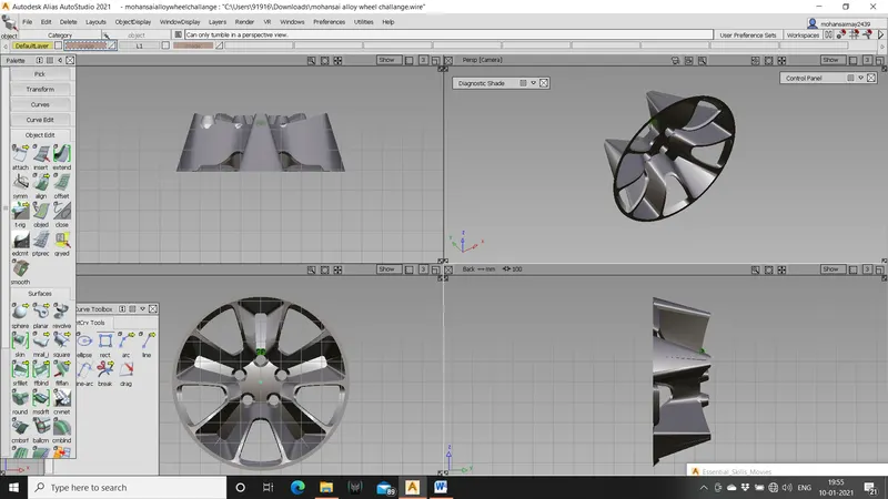
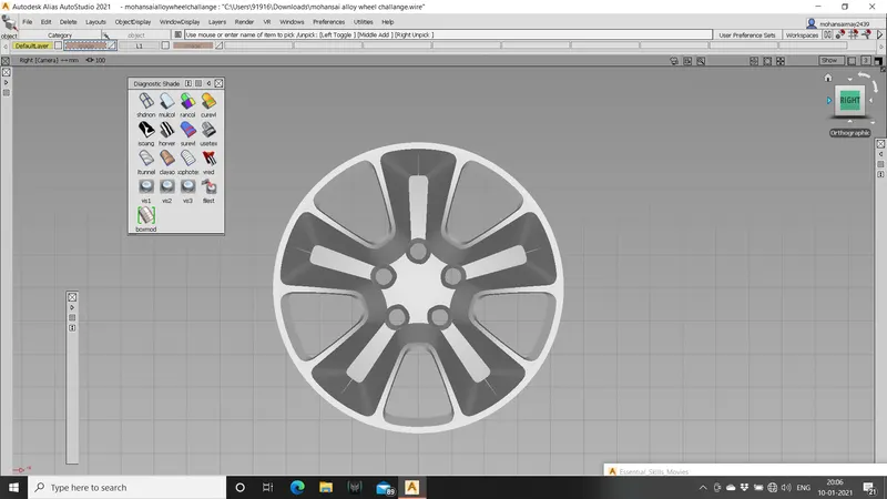
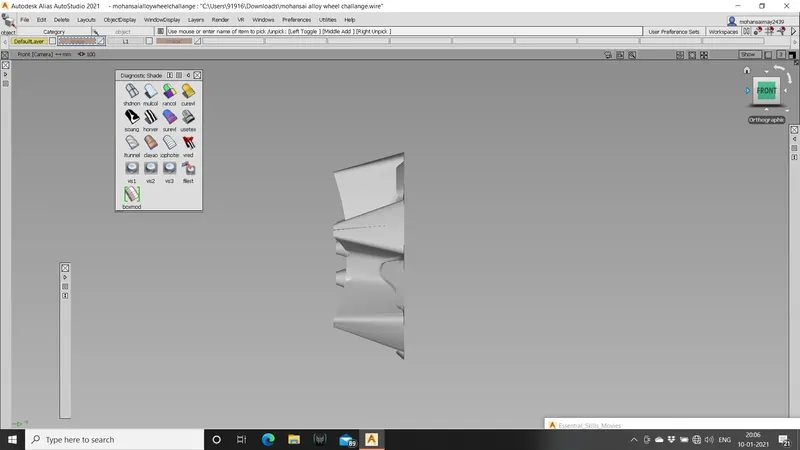
alloywheel 2
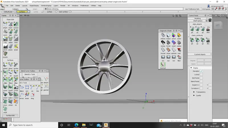
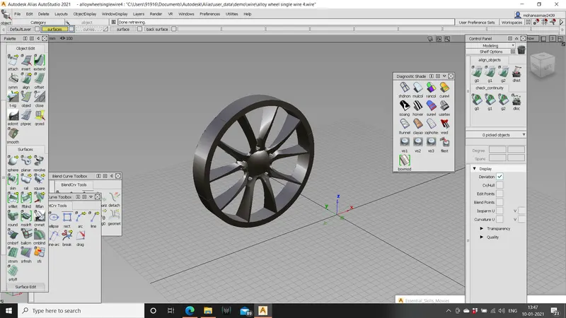
Conclusion: use duplicate object from edit drop menu to revolve the object a certain degree to obtain the complete alloy wheel. Make sure you are aware of how many parts should be duplicated and at what angle to get the part accurately.