Concept Modeling of Side Fender using Autodesk Alias
Title of project: Concept modelling of car fender
Objective: To create surfaces of the entire car fender using isometric image of a car.
Tools used:
Freeform blend tool, CV curves, line, skin, align tool, trim, project, intersect, extend, detach tool, and transform tools, fillet, rail command, Ms Draft etc.
Introduction:
Introduction to surface continuities and its types
Continuity is the smoothness of the junction i.e., two mating curves. Continuity is the condition that the more smoothly the adjoining surfaces flow
Generally there are 4 types of surface continuities i.e., we can have surfaces coming in contact in 4 different ways.
They are:
- G0-position (touching)
- G1- tangent (angle)
- G2-curvature (radius)
- G3-acceleration (rate of change of curvature).
- G0-position (touching) continuity:
This is less smooth type of joint with common end point. This position is the only condition to satisfy the joint.G0 is the point continuity when one curve touches the other and shares the same boundary
- G1- tangent (angle):
One can’t have G1 continuity unless you have G0 continuity.it is also called as second order of continuity i.e., to faces meet along a common edge at a tangent plane they share a common angle. The best example for G1 continuity is a fillet.
- G2-curvature (radius):
G2 adds another order that must match across our pair of curves. For G2 it must a tangent to the curve and have the same curvature a point where they touch I.e., the input geometry must now be curved s well so the input containing a straight line can’t make a G2 curvature.
- G3-acceleration (rate of change of curvature):
G3 continuity includes the concept of acceleration of the curvature; the amount of change in the curvature over the length of the curve.G3 is looking for balance on the rate of curvature.
Description:
- Open auto desk alias and choose class a surfacing.
- Import the canvas image by going to file > import canvas image > always create new layer.
- Assign the canvas to a specific layer.
- Start by visualizing the surface of the fender and how the surface is flowing.
- Get an idea on how the surfaces are flowing in the canvas and develop a strategy to build the surfaces.
- Start by tracing the surfaces using curves.
- Create patches for every part of the fender so that developing of the surfaces can be easier.
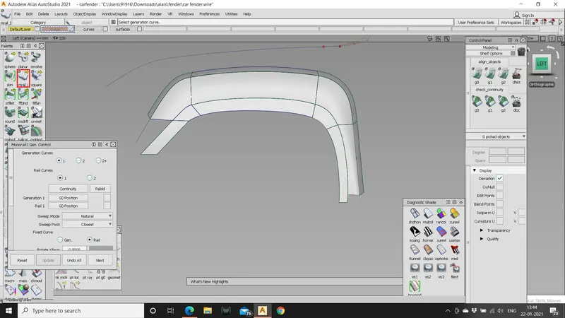
- Using “square” command create the patch layout of the fender.
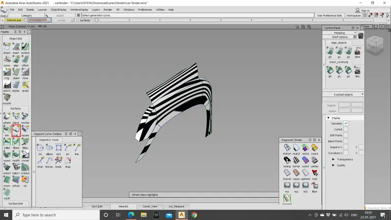
- Use “align” command to form the G2 curvature where ever needed.
- Trace the entire fender by using curves.
- Use “MS draft” command to develop the surface s at an angle to the patch layout which makes easier to develop the surfaces according to the canvas.
- Create hypothetical curves to create surfaces layer they can be trimmed.
- Use “freeform blend” to create a blend between curves.
- As the fender in moving inside at the front the curves should be moved inwards and surfaces should be created as per the flow of the surface of the fender.
- After completing the sharp model save the file and start creating fillets to get smoother edges.
- Use “cos” curves on surface to trim the extra surfaces and clean the model.
- While applying fillets and updating them there will be a lot of load on the system so avoid data loss always save your file at regular intervals.
- Always use chord as construction type while creating fillets.
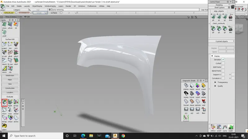
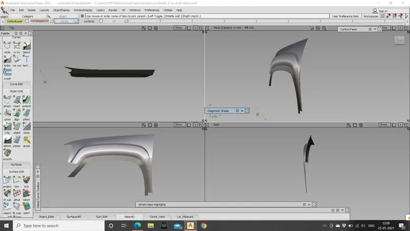
- Finally the model of the car fender is ready with smooth edges.
images.
Conclusion:
The model of car fender is created using the given canvas image as reference using visualization.