Week-11 : Discretization of 3D intake manifold using GEM-3D
1. Tutorial- single cyl DI add case 2 with discretization length 0.1 mm for intake runner and compare with default case 1
-
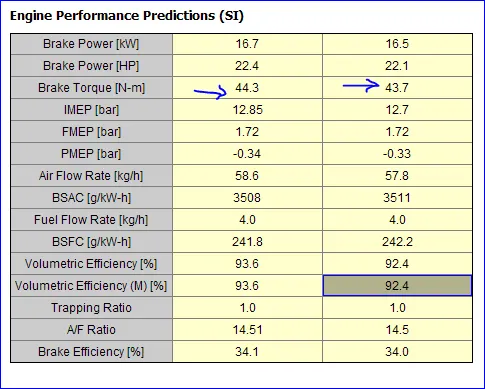
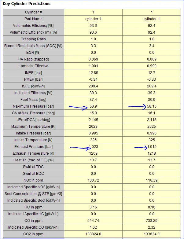
- Parameters-Torque, BSFC, max cylinder pressure
- simulation time
Sol:
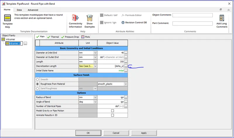
The parameter delat_x is created in the intake runner for the discretization length. It is shown in the figure below:
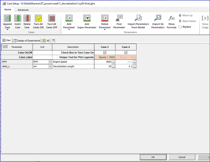
The test cases which were simulated are as follows:
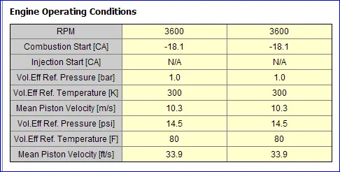
The simulation was run and the following are the results :
| Bore [mm] | 86 | 86 |
| Stroke [mm] | 86.1 | 86.1 |
| Connecting Rod Length [mm] | 175 | 175 |
| Piston Pin Offset [mm] | 1 | 1 |
| Displacement/Cylinder [L] | 0.5 | 0.5 |
| Total Displacement [L] | 0.5 | 0.5 |
| Number of Cylinders | 1 | 1 |
| Compression Ratio | 9.5 | 9.5 |
| Bore/Stroke | 0.999 | 0.999 |
| IVC [CA] | -96 | -96 |
| EVO [CA] | 125 | 125 |
| IVO [CA] | 351 | 351 |
| EVC [CA] | 398 | 398 |
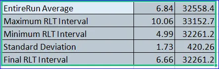
Simulation speed time:
Explore tutorial no 2 (GEM3D) - “Building intake manifold from STL model” (80 marks)
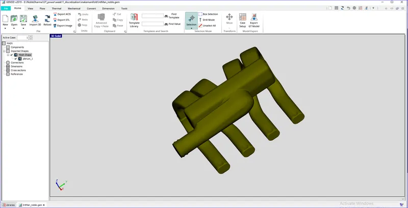
opened the .stl file and now the following operations are performed:
Separating Sections by curves:
Ensurethe part is selected and choose Separate By Curves from the Shape Operations group in the Convert tab. A Toleranceof 1.0 should be used for this operation. Click OK
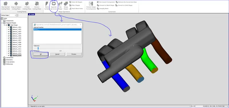
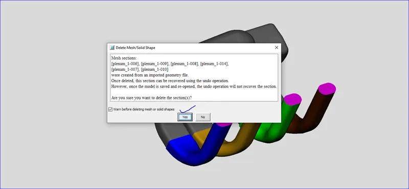
Now that the end sections of the runners and plenum are separated from the main shape, we can delete them from the model. To do this select the 5 end sections (remember to hold down Ctrl to select multiple shapes) and press the delete key.
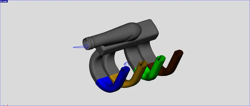
The model should look like the image below, where the inner surfaces are now partly visible through the open ends where the caps were removed.
Using the Cutting Plane
we can continue separating the shape into sections that can be represented by pipes and flowsplits.
- We will start by separating off the 4 runners from the manifold since the runners can be represented by pipes.
-
To do this we will make use of the cutting plane operations available in the Cutting Planes group in the Convert tab.
-
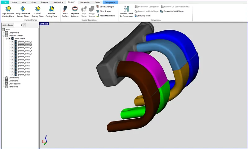
Since we want to cut off the runners, let's pick 3 points on the underside of the manifold block as shown by the black crosshairs in the image below.
Converting Sections into Flow Components:
The first thing we need to do in this window is select the conversion geometry type we would like to convert
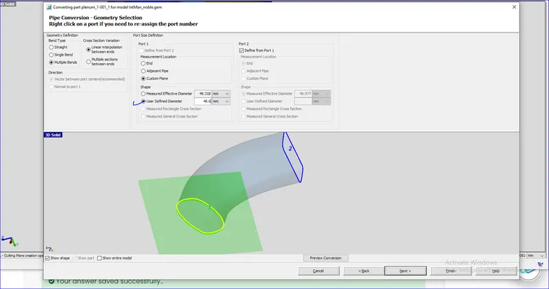
- Since this particular shape is a pipe, select Pipe. Click next. Select Multiple Bends since it has more than 1 bend (notice it also bends in another plane)
-
We need to choose which diameter to use for this cross section using the Measurement Location > Custom Plane for Por This will place a small green plane on the section in the graphical window (just like when using the local cutting plane).
-
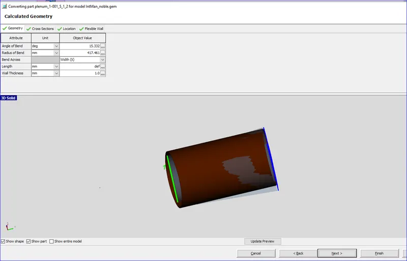
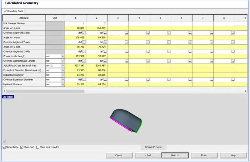
Assume that the diameter stays constant throughout the pipe. Therefore select for Port 2 the check box Define from Port 1 (the example below assumes 48.6 mm). Once in place, press Next and you will see the created component. Confirm that the Wall Thickness is set to 1 mm in the Geometry tab of the Calculated Geometry window and press Next again.
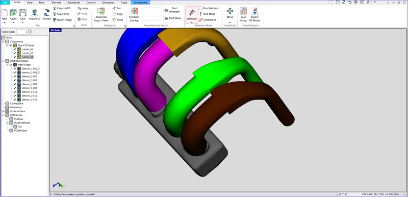
The same process is repeated for all the intake runners and is as shown in figure below:
The process is repeated and the additional surface at the interface as indicated by blue arrow in the figure below.
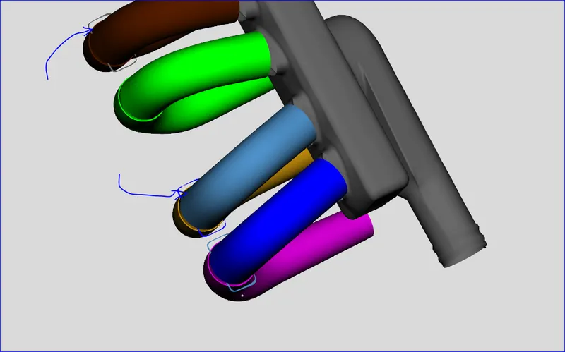
These surfaqces are deleted by selecting them.
Adding a Custom Connection

for the orifice we need to provide the flow coefficient value around 0.9.
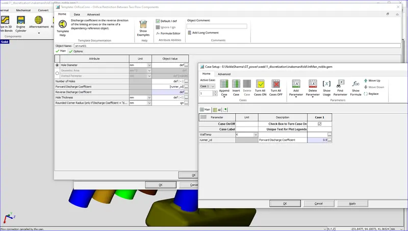
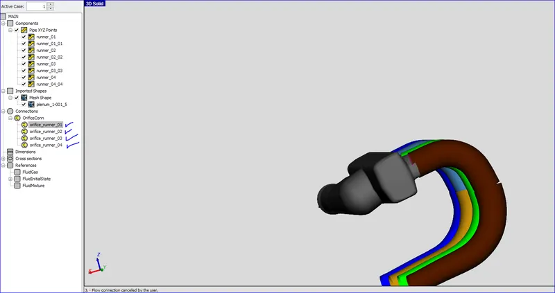
Repeat the above procedure for the rest of the runners using connection names of "ori-run2", "ori-run3", and "ori-run4". When doing this, it is not necessary to go to Case Setup each time since the value was already defined the first time.
You can use the value selector to select the parameter for the subsequent orifice connections since it already exists, thus avoiding potential typing mistakes.
8 Adding a Subassembly Connection to Impose Connection Direction
The next thing we want to do is specify the end (boundary) connections, meaning the connections that do not connect to anything. In our model the ends of each runner need an end connection specified.
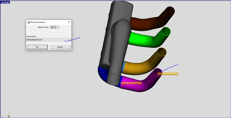
To add the subassembly connection right-click on the end section of the first runner component ("runner_01_01") and choose Add Connection. This will open the port connection window, shown in the image below
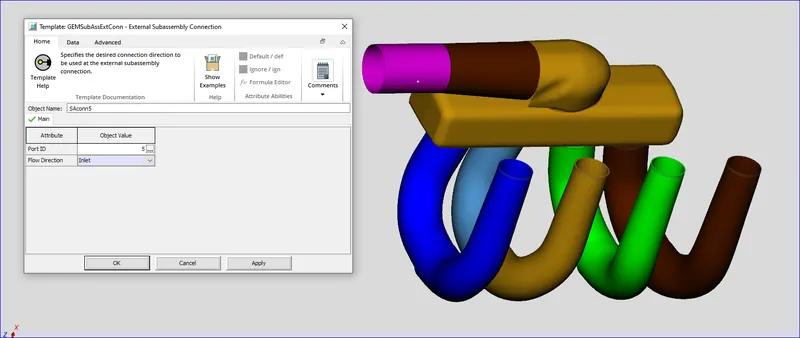
We want to select port 2 (the port not connected to the rest of the runner) and the subassembly connection ('GEMSubAssExtConn'). Click OK and the connection will be added and the appropriate template window will open
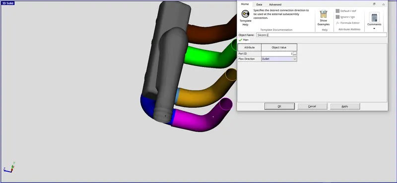
Use "SAconn1" for the name of the component and a Port ID of 1. Set the Flow Direction to "Outlet" since we expect flow to be from the manifold through the runner and out this port.
This allows us to control the flow direction at this boundary, while GEM3D can determine the rest of the directions from any specified values. Click OK to save this connection.
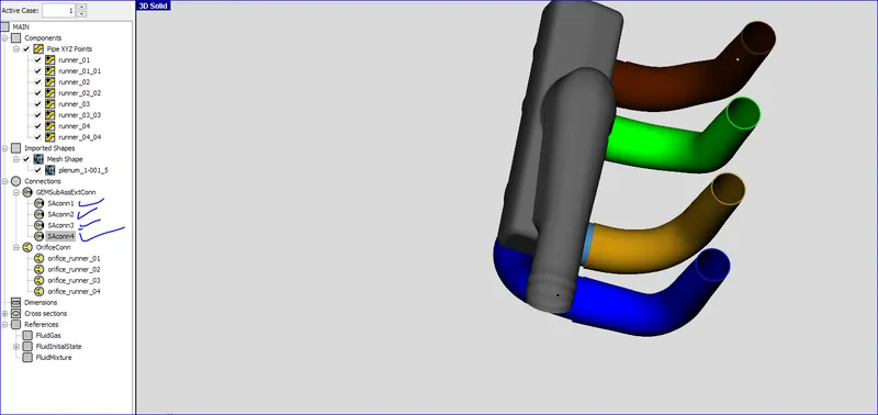
Repeat this procedure for the rest of the runners using names of "SAconn2", "SAconn3", and "SAconn4" along with Port ID values of 2, 3, and 4.
Dividing Pipe Sections with Area Changes
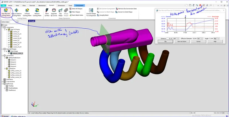
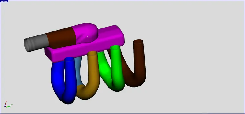
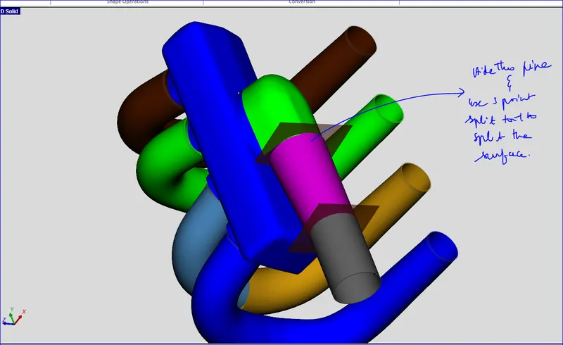
The next step is to convert both of these sections into flow components. Let's start with the D-shaped section by right-clicking on it and selecting Convert Shape to Component. In the convert mesh window that opens choose the Pipe option
Let's switch ports 1 and 2 since they are opposite the expected flow direction. To do this click on Exclude All Ports. Than right-click on the blue outline of the inlet and choose Include Port.
This will assign port 1 to the opening. Do the same for the outlet and click Next. We will model this section as a Straight pipe type with the larger area rather than a taper because the area change is fairly abrupt.
Therefore, for the Diameter for cross section 1 select the checkbox Define from Port 2. Press the Next button to create the straight pipe. Press Next again and give it a name of "pipe2" and click Finish to save the pipe.

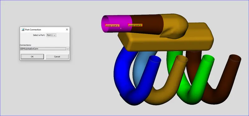
Now we want to specify a subassembly connection on this last pipe since it has an end boundary. To do this right-click on "pipe1" and choose Add Connection. This will open the port connection window, shown in the image below:
Making More Difficult Cuts
Converting Sections into General Flowsplits
Dividing a Large Volume into Smaller Sections (Manual Discretization)
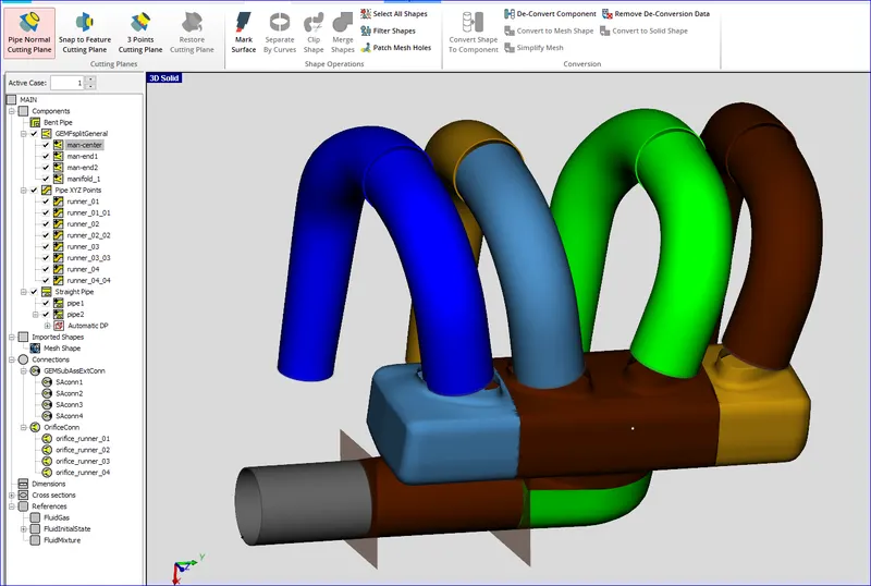
The only mesh shape left to be converted is the manifold section. Rather than converting the entire thing into a flowsplit, we want to manually divide it to get better resolution and accuracy in the GT-SUITE flow model. Manual discretization involves making cuts to divide up the large mesh shape into smaller mesh shapes and converting those into flowsplits
In our case each end of the manifold has a runner connection. Since the center inlet is wide enough to cover both middle runners, the center section of the manifold should cover both middle runners. That means we want to divide the entire manifold into 3 sections; a center section and 2 end sections.
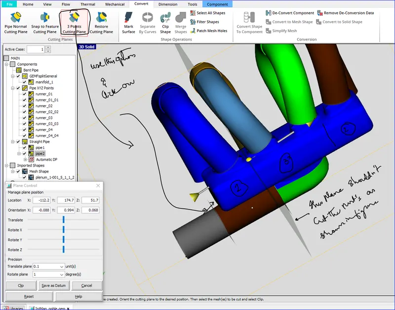
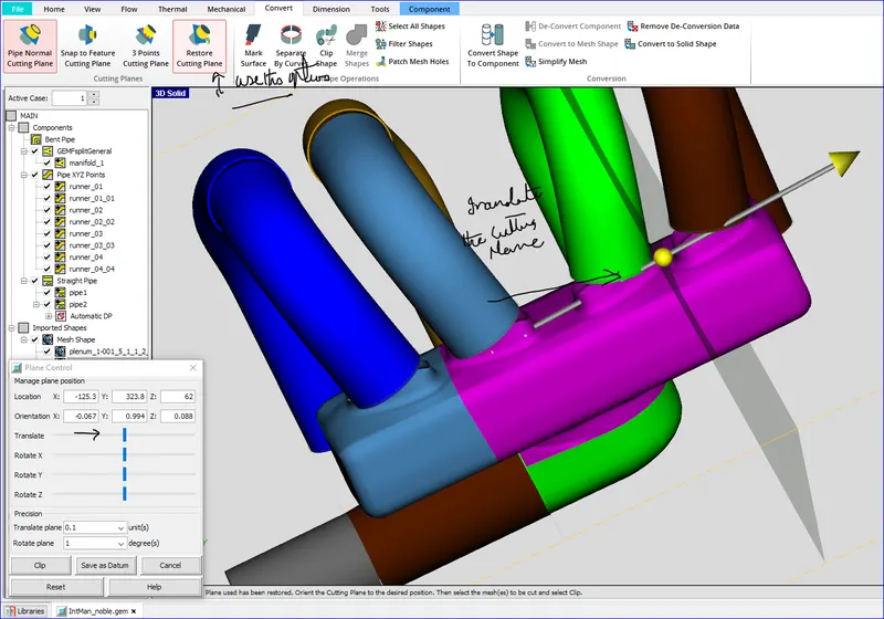
We need to make one more cut between the 3rd and 4th runners to finish dividing the manifold. Rather than picking 3 points again, we can restore the last used cutting plane. To do this, select Restore Cutting Plane from the Cutting Planes group in the Convert tab. This will place a cutting plane at the same location and orientation as the last one used and open the control window
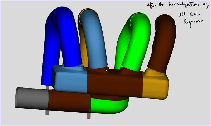
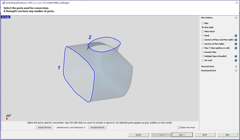
Now that the manifold is divided, we can convert each section into a flow component. Select the end section near runner 1 (red component in the image above), right-click and select Convert Shape to Component.
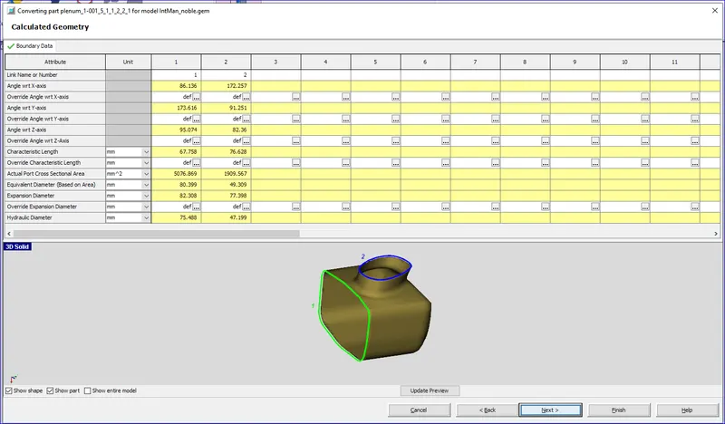
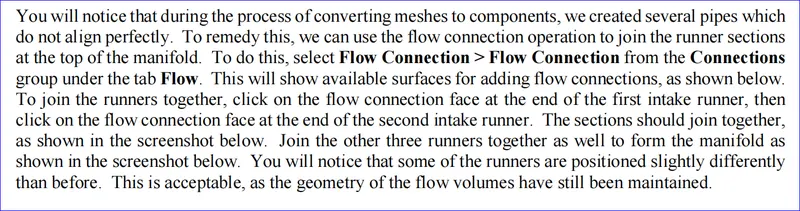
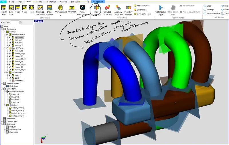
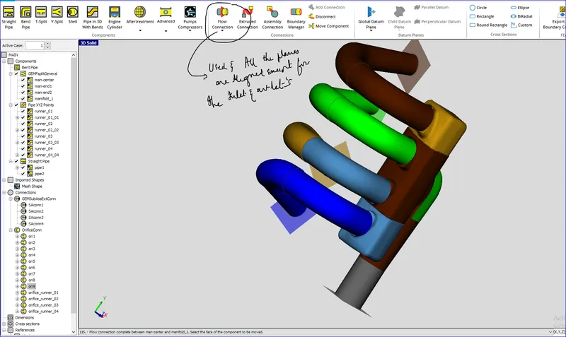
Adding Flow Connections