Week-11 Challenge: Braking
QUESTION 1:
For a defined driving cycle, calculate the energy required for braking.
>>> The Braking performance is one of the most important concerns in the vehicle safety.In urban area driving,a significant amount of energy is consumed in braking.Electrification of vehicle makes it feasible to recover some amount of energy lost in braking.A hybrid braking system was developed to ensure the efficient braking of vehicle and recovering the braking energy.The design and control objective of such hybrid braking system is to ensure sufficient braking force to quickly reduce the vehicle speed,properly distrubuting the brake force to front and rear axle,and also to recover as much braking energy as possible.So understanding of braking energy of a driving cycle is important.
Braking energy can be calculated by the formula
Braking energy = `1/2 *m*v^2`..........Wh
where m = mass of the vehicle in kg
v = velocity of vehicle in m/s
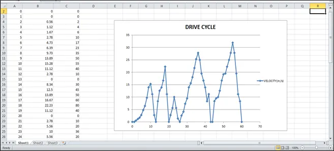
Driving cycle:
https://docs.google.com/spreadsheets/d/1JCMRQL3p6bLj7Lo6TMXiDhLfJs4ik49c6S9Xi86j9iQ/edit?usp=sharing
CODING:
mass=1000;% mass of the vehicle in Kg

t = brake_energy(:,1); %Extracting time column
v = brake_energy(:,2); %Extracting velocity column

% Creating loop to calculate brake energy in Wh

for i = 1:(length(brake_energy)-1)
    if v(i)>v(i+1)
        BE(i) = 0.5*mass*(v(i)-v(i+1))^2; %Brake energy formula
    end
end

fprintf('Total brake energy is %dWh',sum(BE)) %to print the total braking energy value

%plotting

figure(1)
subplot(2,1,1)
plot(t,v,'linewidth',3,'color','g')
xlabel('TIME(s)')
ylabel('Velocity(m/s)')
title('drivecycle')

subplot(2,1,2)
plot(BE,'linewidth',3,'color','r')
xlabel('Time(s)')
ylabel('Braking energy')
title('Braking energy in Wh')
EXPLANATION:
- Import the driving cycle data from excel to the workspace of MATLAB using import command.
- Enter the value of mass of vehicle in kg.
- Extract the time and velocity column and save in a variable called t and v respectively.
- Create a if loop to calculate the braking energy from the driving cycle in Wh.
- Plot the time and velocity values which resembles the driving cycle.
- Plot the braking energy plot from the driving cycle.
RESULT:
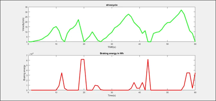

Total Braking Energy obtained is 411.303 kWh
QUESTION 2:
Why electric motor can’t develop braking torque at high speed similar to starting? How electric and mechanical brakes are coordinated?
>>> If the drive motor is being used as generator,it is restricted by the same power limits as when it is acting as a motor because vehicles typically can brake much harder with conventional,friction-based brakes then they can accelerate forward,a vehicle regenerative braking alone will have less braking capability than a vehicle with friction-based brakes.Peak torque during acceleration and deceleration are not equal.Hence electric motor can't develope braking torque at high speed similar to starting.It is virtually impossible and actually impractical to recover all braking energy at high speed or high deceleration rates. Braking power is not only limited by the motor's power rating,but by the charging power limit of the battery pack.This limits depends upon the chemical composition(battery type) and changes with temperature.This makes analyzing the braking power capability difficult,as a vehicle may be able to regen-brake at full power for a short period of time but as the temperature of the battery pack rises,the braking power will quickly fall.The exact amount of energy and the rate of energy that can be recovered is dependent on the available motor,battery types and the driving scenario.A more serious issue arises when regenerative braking is applied to a two-wheel-drive brake system.When regenerative brakes kick in,negative torque is applied to the drive wheels,and wheels with no brakes will spin freely.This uneven distribution of negative torque causes uneven tire and brake wear.This could potentially cause skidding on the wheels with brakes.At low speed (lower than its base speed), the maximum torque is constant.However, at high speed (higher than its base speed), the maximum torque decreases hyperbolically with its speed hence electric motor can't develope braking torque at high speed similar to starting.
How electric and mechanical brakes are coordinated ??
Regenerative braking in EVs and HEVs becomes complex to the braking system design.Regenerative braking is effective only for the driven axle. The traction motor must be controlled to produce the proper amount of braking force for recovering the kinetic energy as much as possible and, at the same time, the mechanical brake must be controlled to meet the braking force command from the driver. Basically, there are three different brake control strategies:
- Series braking.
- Parallel braking.
SERIES BRAKING:
The series braking system of a braking controller that controls the braking forces on the front and rear wheels. The control objective is to minimize the stopping distance from the safety point of view and optimize the driver’s feel from comfort point of view.The braking force on the front wheels (driven axle) is divided into two parts: regenerative braking force and mechanically frictional braking force. When the braking force demanded is less than the maximum braking force that the electric motor can produce, only electrically regenerative braking will apply. When the commanded braking force is greater than the available regenerative braking force, the electric motor will operate to produce its maximum braking torque, and the remaining braking force is met by the mechanical brake system. It should be noted that the maximum regenerative braking force produced by an electric motor is closely related to the electric motor’s speed. At low speed (lower than its base speed), the maximum torque is constant.However, at high speed (higher than its base speed), the maximum torque decreases hyperbolically with its speed. Therefore, the mechanical brake torque at a given vehicle deceleration varies with vehicle speed.
PARALLEL BRAKING:
The parallel brake system includes both an electrical (regenerative) brake and a mechanical brake, which produce braking forces is parallel and simultaneously.The parallel brake system has a conventional mechanical brake which has a fixed ratio of braking force distribution on the front and rear wheels.Regenerative braking adds additional braking force to the front wheels,resulting in the total braking force distrubuation. The mechanical braking forces on the front and rear axles are proportional to the hydraulic pressure in the master cylinder. The regenerative braking force developed by the electric motor is a function of the hydraulic pressure of the master cylinder, and therefore a function of vehicle deceleration. Because the regenerative braking force available is a function of motor speed and because almost no kinetic energy can be recovered at low motor speed, the regenerative braking force at high vehicle deceleration is designed to be zero so as to maintain braking balance. When the demanded deceleration is less than this deceleration, regenerative braking is effective. The parallel braking system does not need an electronically controlled mechanical brake system. A pressure sensor senses the hydraulic pressure in the master cylinder, which represents the deceleration demand. The pressure signal is regulated and sent to the electric motor controller to control the electric motor to produce the demanded braking torque. Compared with the series braking ,the parallel braking system has a much simpler construction and control system.
QUESTION 3:
Make a MATLAB program which plots contour of given motor speed, torque and efficiency values. Attach the code as a .m file attach a screenshot of all the plots
>>> To plot contour line for a given motor.A motor have various types of losses they are
COPPER LOSSES:
Copper loss is the term often given to heat produces by electrical currents in the electrical devices.Copper losses results from Joule heating and so are also reffered to as 'I square R losses',in reference to Joule's First Law.This states that the energy lost each second,or power increases as the square of the current through the windings and in proportional to the electrical resistance of the conductors.
`Copper loss prop I^2.R`
`Copper loss=k_c*T^2`
Where I is the current flowing in the conductor and R is the resistance of the conductor.With I in amperes and R in ohms,the calculated power loss is given in watts.
IRON LOSSES:
As the armature core is made of iron and it rotates in a magnetic field,a small current gets induced in the core itself.Due to this current,eddy current loss and hysteresis loss occur in the armature iron core.Iron losses are also called as core losses or magnetic losses.At various speed have different value of Back EMF and that is going to affect the iron losses.
`Iron loss = k_i*omega`
WINDAGE LOSSES:
This is a Mechanical or friction windage losses.This is based on the size and shape of the motor and the amount of windage losses that the motor is going to experience
windage losses = `k_w*omega^3`
MATLAB CODING:
clear all
close all
clc

% A program for plotting efficiency contours for electric motors.


% First, set up arrays for range.
x=linspace(0,2000);% speed, N.B. rad/s NOT rpm % The x axis corresponds to motor speed (w)
y=linspace(0,500); % 0 to 500 N.m % and the y axis to torque T

% Allocate motor loss constants.

kc=1.5; % For copper losses
ki=0.1; % For iron losses
kw=0.00001; % For windage losses
ConL=20; % For constant motor losses

% Now make mesh
[X,Y]=meshgrid(x,y);

Outputpower=(X.*Y); % Torque x speed = power

B=(Y.^2)*kc; % Copper losses

C=X*ki; % Iron losses

D=(X.^3)*kw; % Windage losses

Inputpower = Outputpower + B + C + D + ConL;

Z = Outputpower./Inputpower;

% We now set the efficiencies for which a contour
% will be plotted.
V=[0.70,0.75,0.80,0.82,0.85,0.87,0.90,0.93,0.95];
box off
grid off
contour(X,Y,Z,V);

xlabel('Speed/rad.s^-^1')
ylabel('Torque/N.m')
title('EFFICIENCY CONTOUR PLOT')
EXPLANATION:
- Start the coding with clear all,close all and clc to erase all the data stored in the workspace of the MATLAB.
- Create speed and Torque array using linspace command.
- Specify the motor loss constant values which are used during the calculation of motor losses.
- Create a mesh of speed and torque using meshgrid command.
- Calculate the output power using a formula POWER = SPEED*TORQUE.
- Calculate the losses using the formula.
- Calculate the efficiency using the formula efficiency = output power/input power
- Plot the contour which represents the torque,speed along with the efficiency contour lines.
- Indicate the x-axis and y-axis using label command.
RESULT:
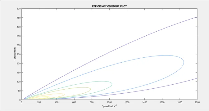
The above plot represents the Torque along Y-axis and Speed along X-axis along with the efficiency conotur lines.As a EV design egineer we must know the efficiency of motor corresponding to its operating point which can be obtained by the above plot and inner contour is having the highest efficiency.