Week-11 Challenge: Braking
Solution:
Q.No. 1:
Drive cycle cosidered - US06
The US06 is a high acceleration aggressive driving schedule that is often identified as the "Supplemental FTP" driving schedule.
The chart considered for calculation is downloaded from https://www.epa.gov/
The speed in mph is converted into m/s (1 mph = 0.447 m/s)
The energy required for breaking is given by
Breaking Energy , BE = 1/2(m*(v)^2)
= 1/2(m*(vf-vi)^2)
where,
m = mass of vehicle
vi = initial speed of vehicle
vf = final speed of vehicle
Mass is assumed as 1000 kg.
Breaking energy calculation,
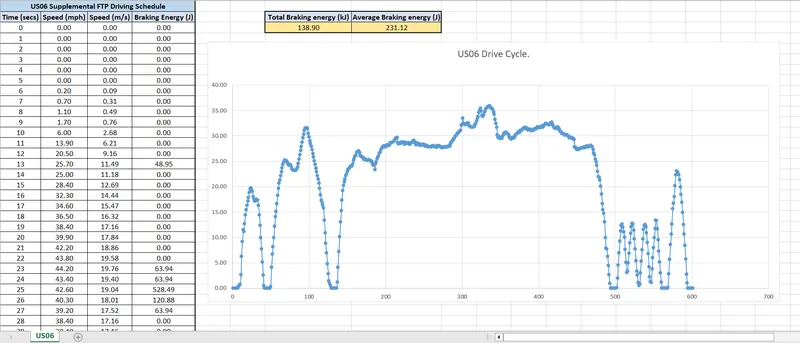
Total Braking Energy = 138.9 kJ
Average Braking Energy = 231.12 J
Q.No. 2:
In electric motors, maximum torque is produced from the get-go. As a current flows through the electric motor, a related electrical charge causes an armature to rotate. These rotations within an internal magnetic field cause something called a back-EMF (electromotive force) which opposes the supply voltage. Imagine back-EMF to be the equivalent of a natural braking force, much like in IC engines.
The net overall force being applied to the wheels is therefore the difference between the supply voltage and the EMF. The back-EMF is proportional to speed, therefore the higher the speed, the smaller the net overall force is. This explains why the torque curve begins to diminish on an EV dyno graph as the car’s electric motors are pushed into the upper ranges of their performance limits.
In case of braking, because we are operating in the field weakening region, and operating above the base speed, Peak Acceleration torque is greater than the Peak Deceleration torque. Thus for acceleration it has high torque with low speed and for deceleration it has low torque for high speed.
Mechanical Braking
Mechanical brakes are applied by brake shoes which are pressed with force against the wheel of the train. In mechanical braking, the braking force is generally produced by means of piston-cylinder arrangement. The movement of the piston is transmitted to the brake shoes through a system of levers.
Electric Braking
In electric braking, the kinetic energy of the moving parts of the motor is converted into electrical energy which is either dissipated in a resistor or returned to the supply source. Thus, electric braking is a system of braking in which a braking action is applied to an electric motor by causing it to act as a generator.
Electrical and mechanical braking systems can are coordinated by using a Brake strategy subsystem
1) Serial Braking Strategy
2) Parallel Braking Strategy
- Implementation of serial braking strategy
Once the brake pedal is pressed and depending on the level of depression, brake torque is sent. Now, this brake torque passes into the brake control strategy block. Here, firstly it is checked if the battery state-of-charge is below 80% which is set as the maximum permissible level of charge. If that condition is satisfied, then the battery is recharged. The brake torque requested is compared to the maximum regenerative torque limit of the motor-generator. If the overall brake torque requested is less than or equal to the maximum regenerative torque, then the vehicle brakes purely on regenerative torque, and the battery is charged. The amount of charge ultimately put in depends also on the motor-generator operation efficiency and the battery charging efficiency. If the overall brake torque requested is greater than what the motor-generator can provide, then the friction brakes kick in. Now since the vehicle is front-driven, it is checked if the total brake torque requested from the front is less than or equal to the maximum regenerative torque capability of the motor-generator. If yes, then front braking is provided purely by regeneration and rear (non-driven axle) by friction. Once the total brake torque request increases further, then front friction brakes (driven axle) come into play in combination with rear friction brakes and front regenerative braking, to satisfy the overall brake torque demand.
- Implementation of parallel braking strategy
Once the brake pedal is applied and a desired overall brake torque request is sent from the driver block. This braking torque on passing through the brake control strategy gets divided between regeneration and friction braking at all times. The strategy is so modeled with the comfort and brake pedal feel in mind. As parallel regenerative braking is an add-on to conventional systems, it is devoid of any integrated control. So to make the transition and eco-performance of regenerative braking with friction smooth, it is assigned in such a way that, there is a clear division between the amount of brake torque that will be achieved from regeneration and friction braking. On application of brakes and in keeping with the design of the motor-generator, it is designed to operate the generator in a constant generator torque region. Motor-generator can provide a maximum of 322 Nm of generator torque at or under the base speed. The generator is scaled such that the base speed of the generator corresponds to a velocity of 124 [kmph], which is the maximum speed limit on most highways. Hence regeneration works, as long as the vehicle is braking from a speed of under 124 [kmph] and the requested brake torque on the front-driven wheels, after the front-rear brake split is greater than or equal to maximum generator torque. If that condition is satisfied, then regenerative and friction braking operate in tandem; else it’s just the friction brakes at the driven and non-driven axle.
Q.No. 3:
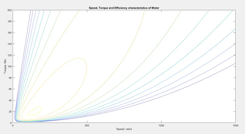
Below are the various losses that occur in the motors operation which needs to be considered for efficiency calculation:
- Copper loss
- Iron loss
- Winding loss
- Conduction loss
These losses are dependent on the speed and the torque of the motor.
- Copper loss = Kc*T^2
- Iron loss = Ki*w
- Windage loss = Kw*w^3
T - Torque
w - Speed
Kc, Ki, Kw - constnt of proportionality
The values of coefficients are taken as general values. Constant motor loss (conduction loss) is assumed to be 20 Joules.
Input Power = Output power + All losses.
Efficiency = Output Power/Input Power
MATLAB Code:
Plot: