How EV's Breaking system work?
AIM`to`
To understand the braking feature in EV's
OBJECTIVE -1 `to` For a defined driving cycle, calculate the energy required for braking.
OBJECTIVE -2 `to` Why electric motor can’t develop braking torque at high speed similar to starting? How electric and mechanical brakes are coordinated?
OBJECTIVE -3 `to` Make a MATLAB program which plots contour of given motor speed, torque and efficiency values. Attach the code as a .m file attach a screenshot of all the plots
THEORY`to`
Braking of Electric Motors - Braking is as important as the acceleration.It is the important factor from safety point.
Methods of Braking -
- By applying friction (i.e. disc brakes),
- by engine braking (i.e. by lowering the gears, like from gear 4 to gear 2 and by doing so we may feel the jerk. Mostly used by truck drivers or when brake pedal is failed),
- by jake brake (R) or compression release engine brake (i.e. by gradual release of air inside the cylinder one by one, also a type of engine break, these are used mainly in diesel trucks)
Note - The braking in EV is done by Brake Motor.
Brake Motor - These motors will have additional brakes mounted on their shafts. These are based on friction, not on the regenertive braking. These types of brake motors are present in cranes.
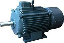
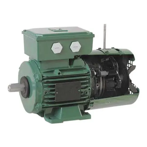
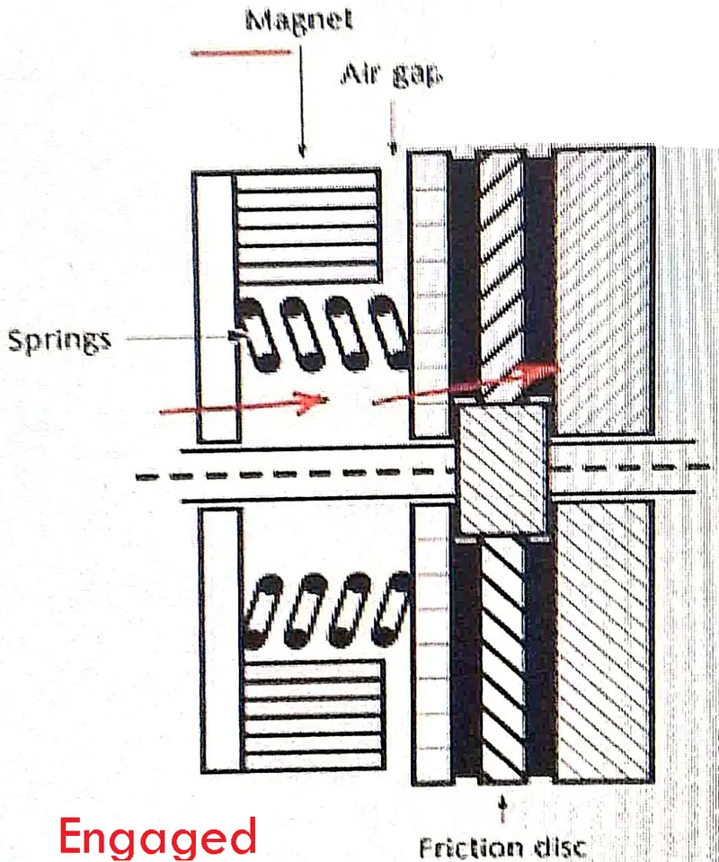
Here, after the motor shaft comes the brake module. This includes a brake disc, which engages (brake applied) whenever the supply to motor is cutoff and makes the motor shaft to stop. We can say that the non driving end is the brake module part and the driving end is where the mechanical load is applied to the motor shaft. The brake disc actually is a spring-electromagnet arrangement.
The first picture is when the brakes are not applied since there is air gap and in the picture there is no air gap, so the brakes are egaged. Usually this type of brake motor arrangement is not found in an EV or HEV. But the principle is similar.

ELECTRIC BRAKING - Breaking by which the motor inherently applies break. Here the propulsion power (i.e.battery) itself provides the braking power.The simple schematic diagram of of EV power train is shown below. Here the battery (B) is the source providing the power required for propulson of the motor (M). This motor is coupled with the wheel.
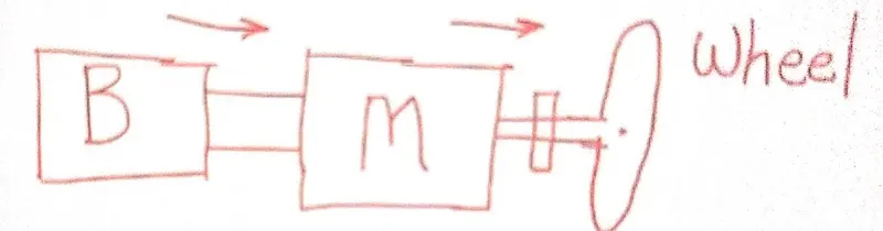
when the throttle is released and there is no more power given to the motor from the battery, also no breaks are applied, then this condition of the vehicle movement is called as coasting (free running).
(In case of IC engines, if the speed is dropped from 80Kmphr to 0 by running the vehicle in Neutral. Hence at this time the brake time required will very large.If the speed of the
And there is no chance of the wheel of the vehicle to turn in opposite direction (unless it is reveresing), so, we can say that the speed is always positive. And if the vehicle is accelerating then the torque is also positive (i.e. forward motoring) and if the torque is negative (i.e. forward braking), then also the speed is positive.
so we are interested in forward braking, wherein the vehicle is stopped in forward motion. How it can be done?
In Tesla car's, there is no brake pedals. Actually, if the throttle pedal is released, the corresponding amount of brakes are applied. It is said to have a regenerative braking. But for regenerative braking, the motor has to function as a generator by the help of its motor controller, to send back the Kinetic Energy of the wheels cum motor, into the electrical energy, back to the battery. That brings us to the electrical machines.
MACHINES - The electrical terminolgy machines involves Motor & Generator.
MOTOR - is an electrical machine that converts electrical energy into mechanical energy. In the below picture, we can see that the current (i.e. from the battery) carrying armature conductors is placed between the two magnets. When the battery is turned on, there is a flow of current in the conductors and magnetic field from the north to the south. By Fleming’s left hand rule, we understand that there is a downward and upward force acting on the conductor. This is known as motoring action on armature conductors.
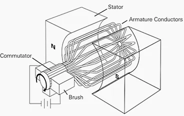
GENERATOR - Suppose in the above figure, there is no battery an brush part. And the armature conductors are connected to an external shaft that rotates these armature conductors in clockwise direction at `omega`speed. Since these armature conductors are placed in the magnetic field, these conductors will experience the rate of change of magnetic field linked with it (`(dphi)/(dt)`). Since there are many conductors, we have to take 'N' as the number of conductors (or no: of turns if it is having a core). These two factors when taken into consideration, will be resposnsible for an EMF generation in the conductors.
i.e. `epsilon prop N(dphi)/dt`,
where `(dphi)/dt to`magnetic field linkage, `N to`no: of turns,`omega to`speed in radians
So we can say that the generator works on the principle of rate of change of magnetic field. This EMF generation indces a current flow in the conductors, which can be fed back to the battery for charging. Hence we can say that the generator is a machine tat converts mechanical energy into electrical energy. This is known as generating action on armature conductors.
NOTE - You can see the rate of change of magnetic field `(dphi)/dt` is also happening in the case of motoring by the same principle as above. So we can say that there is generator effect while motoring (i.e. `epsilon_b prop N(dphi)/dt`). This EMF is called Back EMF (`epsilon_b`).
FUNDAMENTAL EQUATIONS OF DC MACHINE
`omega to`speed in radians
`phi to` free flux or flux per pole in weber
`Kto` constant of proportionality. Also for separately excited motors, `Kphi to` is constant of proportionality.
`epsilon_b to` Back EMF
`epsilon_g to` EMF produced in the Generator
`T to` Torque
`I_a to` Armature Current
`R_a to`armature resistance (i.e. motor load or geneator load)
`V to` applied voltage
Equation 1 `to` `epsilon_b = K*phi*omega`. For a Generator, `epsilon_b = epsilon_g`
Equation 2 `to` `T = K*phi*I_a`
Equation 3 `to`
Consider the below circuit diagram,
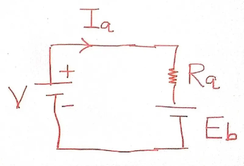
This circuit diagram is suitable for a motor (`R_a`). Here motoring action wll take place when the`V>epsilon_b`. Hence the`I_a` will be in clockwise direction (+ve sign for `I_a`).
Therefore, by Kirchoff's Voltage Law, `V=I_a*R_a + epsilon_b`
If `V<epsilon_b`, then the`I_a` will be in anti-clockwise direction (-ve sign for `I_a`).
Then, by Kirchoff's Voltage Law, `V=epsilon_b - I_a*R_a `
Equation 4 `to` `omega = (V/(K*phi)-((R_a*T)/((K*phi)^2)))`
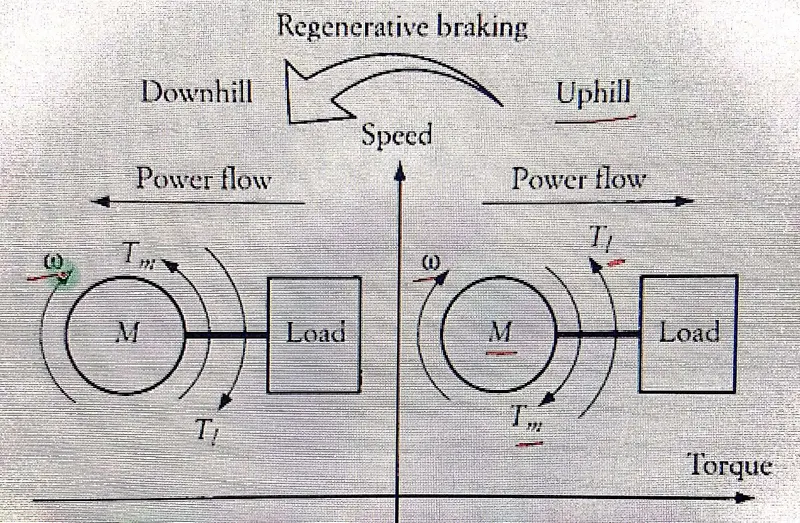
FUNDAMENTALS OF REGENERATIVE BRAKING - Regenerative braking is an energy recovery mechanism that slows down a moving vehicle or object by converting its kinetic energy into a form that can be either used immediately or stored until needed. In this mechanism, the electric traction motor uses the vehicle's momentum to recover energy that would otherwise be lost to the brake discs as heat. This contrasts with conventional braking systems, where the excess kinetic energy is converted to unwanted and wasted heat due to friction in the brakes, or with dynamic brakes, where the energy is recovered by using electric motors as generators but is immediately dissipated as heat in resistors. In addition to improving the overall efficiency of the vehicle, regeneration can significantly extend the life of the braking system as the mechanical parts will not wear out very quickly.
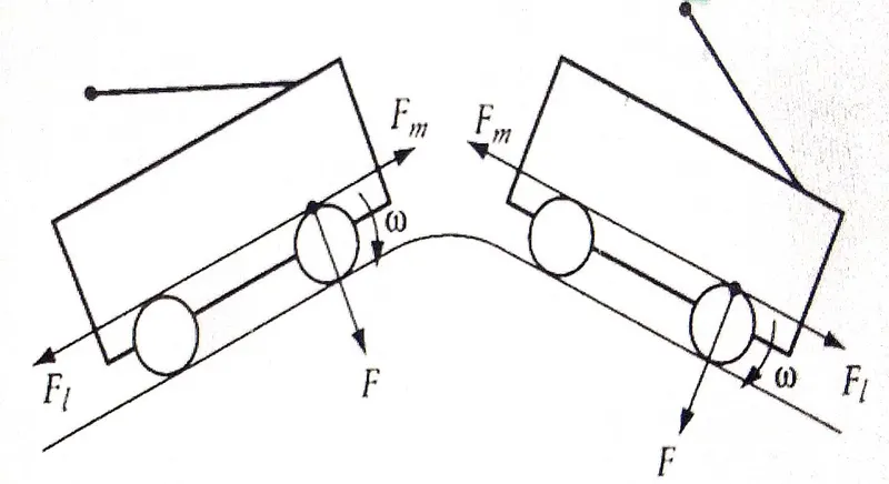
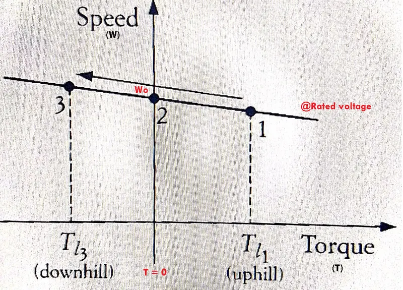
suppose the vehicle is moving uphill and then goes downhill. The corresponding speed, torque and power flow has been shown as in below -
REGENERATIVE BRAKING IN DC MOTOR
The speed torque characteristics for the above case is as follows -
You can see the 2 quadrant characteristics at rated voltage. The point 2 is having a speed at no-load condition (`omega_0`).
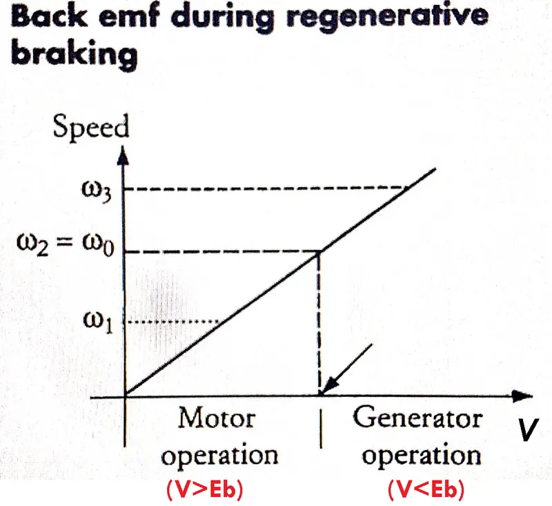
It is not necessary to have a downhill condition to activate the regenerative braking. We can have the regenerative braking when the variable voltage (`V`) greater than the back EMF (`epsilon_b`) (i.e. `V<epsilon_b`). This is depicted in the below graph of Speed vs Voltage.
Types of Regenerative Braking in DC motor
can be done by `to`
- braking by operating the DC motor above the no load speed
- braking by operating the DC motor below the no load speed, given that variable voltage must be done
- Dynamic braking of a DC motor
- terminal voltage reversal of DC motor
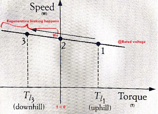
1. Above `omega_0` - This happens for the natural characteristics of the motor, (i.e. without any power converter). This is when someone is driving externally above the no load speed (`omega_0`)
2. Below `omega_0` - This happens in the presence of a power converter, where variable voltage source is applied. For eg:- there are 2 characteristics, one at rated voltage and the other at half of the rated voltage. In both the condition, the regenerative breaking can happen.
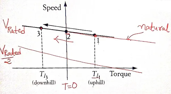
NOTE - For the EV application we are mainly focusing on the "Below `omega_0`" type of regenerative breaking. So for the variable voltage source, we need an arrangement similar to the step down converter or the chopper, preferably 2 quadrant chopper.
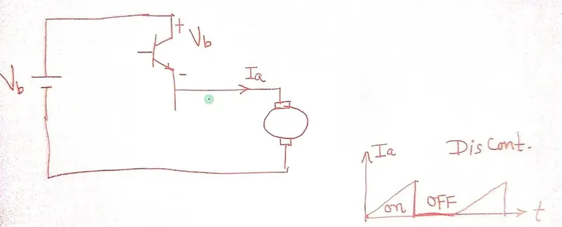
First quadrant chopper - This converter will have only one transistor switch and the corresponding current vs time graph is shown below. You can see there is ON & OFF variation. Such a discontinous variation is not advisable for a motor. Because the motor will have inductance causing inductance current, which is not suppose to be interrupted instantaneously. There is the high possibility of the switch to get breakdown due to the high instantaneous voltage drop across its terminals.
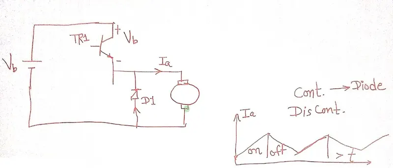
To make this instantaneous current negligible, a diode (i.e. freewheeling diode) is connected in parallel to the motor. This will make the `I_a` continuous. The modified circuit is as shown below.
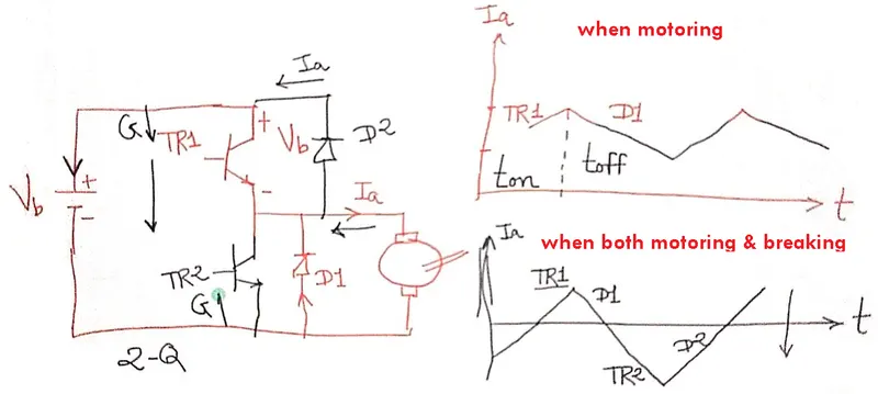
But we need a 2-Quadrant chopper which will fed back the current back to the battery or external voltage source. For that we need a bidirectional power converter. So when breaks are applied or when the motor applies the breaks, the duty cycle is reduced, but the path for the flow of reverse current is not present. Hence, we need an additional switch and a diode in the circuit. They are shown in black colour in the circuit. Therefore, when the switches TR1 and TR2 are in OFF state, the current will pass through the diode D2 and the battery will be charged.
TR1 can be assumed to be controlled by acceleration pedal and tr2 by the brake pedal.
FOUR QUADRANT OPERATION OF DC MOTOR
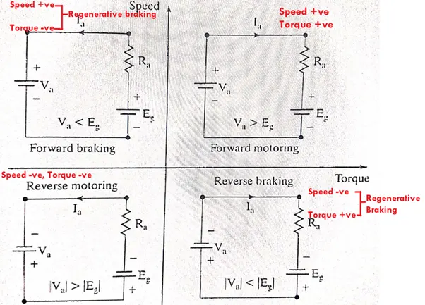
NOTE - The regenerative braking is a very good feature to be implemented in EV's. But suppose if do not have the 2-quadrant chopper or bidirectional current flow facility and in place of feeding back the energy back to the battery, we will use that energy in some other electrical element. Such a type of braking is called Dynamic Breaking.
3. DYNAMIC BREAKING - The type of breaking where we do not get the energy but this energy is dissipated to other electrical components. It is done by connecting the motor terminals to a resistance, instead of connecting to the battery or source.
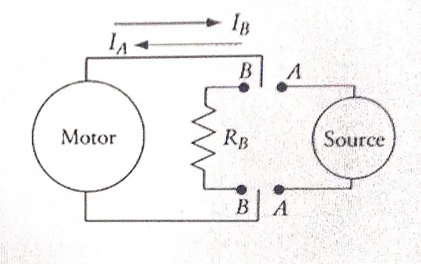
What is use of connecting a resistance to the motor terminals? - If the motor terminals are not connected to the resistance(`R_b`) or they are kept as open, then the current (`I_b`) due to the motor working as generator will be of no use and the motor will be stopped by means of friction and windage losses (i.e. by mechanical means and not by electrical energy). This will make the breaking time to increase sufficiently. And if the resistance is applied, then depending on the values of `I_b` and `I_a`, the breaking time will be reduced correspondingly.
So you see that there is no voltage source or battery while dynamic breaking. Then as per the equation, `to` `omega = (V/(K*phi)-((R_a*T)/((K*phi)^2)))`
here the term `V/(K*phi)` is 0, as V=0. Therefore, `omega = -((R_a*T)/((K*phi)^2)))` (i.e. no y-intercept). The characteristics will pass through the origin. And also the slope of the characteristics will increase because now we have added `R_b` along with some of the motor load (i.e. `R_a`). The characteristics is as shown below. So we can say that the value `(I_b)^2R_b t` is the breaking energy required for dynamic breaking. But this is not an efficient way of breaking, since it is of high wattage (i.e. large power). This means that the resistor used as `R_b` is of large value.
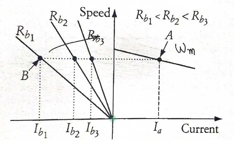
Note - further severe braking happens when the terminal voltage is reversed.
4. TERMINAL VOLTAGE REVERSAL IN DC MOTOR - The reversal of voltage or terminal voltage is a very severe in practical application, because, refer the figures below -
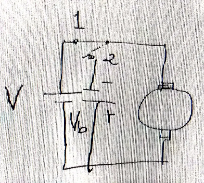
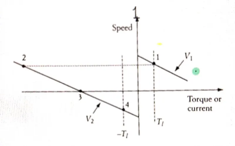
From the circuit diagram shown above, we have depicted a switch configuration which will assist in voltage reversal. And the corresponding characteristics is shown. The `V_1` voltage is the characteristics by switch 1 and when we reverse the voltage, the point 2 is the position when the voltage reversal happens. You cans ee the difference in torque values at point 1 and 2. Torque at 2 is very large. The ultimate point to reach while voltage reversal is point 4 (i.e. 1`to` 2 `to` 3 `to` 4). By the time it reaches point 4, the braking torque will be very large. To avoid this large braking torque, we will add the resistance `R_b`. With this modification, we can use dynamic braking for EV's
BRAKING IN INDUCTION MOTOR (IM)
can be done by`to`
- regenerative braking,
- braking by voltage reversal,
- braking by single phasing of IM
1. REGENERATIVE BRAKING IN INDUCTION MOTOR
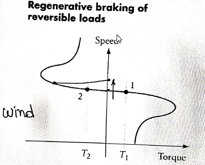
For induction motor, the speed should be greater than the no load speed (i.e. `omega_0`). The best example for regenerative braking in induction motor can be seen in wind turbines.
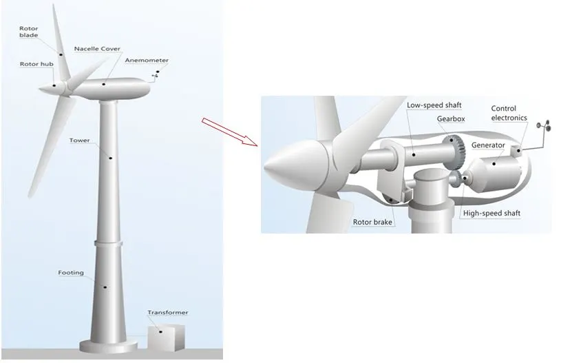
Since wind turbines doesn't need the blades to rotate at large rpm's, but their slow speed rotation can be modified to high rotation using a gearbox. Th prime mover in a wind turbine is the Induction motor. This can be done by designing the motor as per the need. Like, `N_s = (120*f)/P`, if we increase the number of poles, then automatically the rpm (`N_s`) value will be decreased.
From the characteristics below, the wind turbine will function most of the time at point 2, which is more than the no load speed (i.e. `omega_0`). So, working at point 2, we will get the power back from the wind turbine.
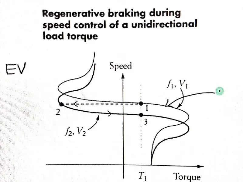
But the induction motor regenerative braking for an EV application, we will need variable voltage and variable frequency (VVF). Suppose the characteristics for point 1 is running at 40Kmph, and now i want to make it to point 3 at 20Kmph. The regenerative braking will happen by point 1 moving to point 2 then at last to the point 3. The power generated to reach point 2 is fed back to the source for charging purpose.
2. VOLTAGE REVERSAL IN INDUCTION MOTOR
The voltage reversal or the direction reversal in an induction motor can be done by interchanging any two terminals of 3 phases of induction motor. For eg:- ABC connection in clockwise rotation can be changed to anticlockwise rotation by ACB connection. The two connections rotating magnetic field space vectors variation is as shown below.
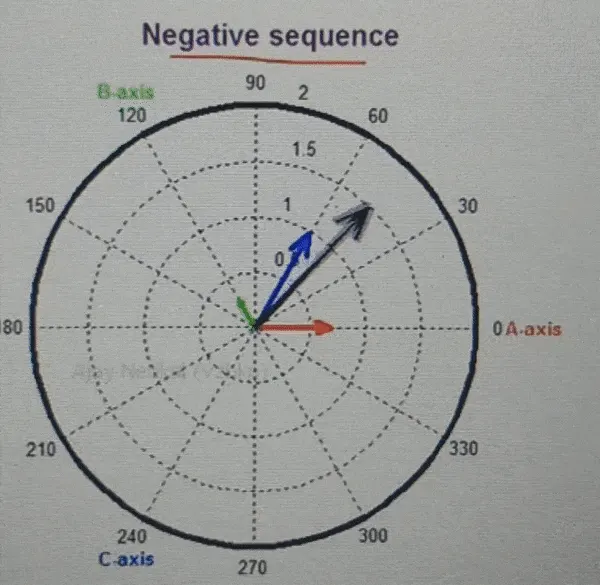
The corresponding characteristic during regenerative braking for voltage reversal is as shown below. You can see in ABC sequence, the operating point is point1. Then when we apply the break and reversal of the voltage happens to reverse rotation of the induction motor, then the operating point is point 4. But to reach 4 from1, point 2 has to be undergone by the point 1. Hence when reversal of induction motor happens, it has to go through the 2nd quadrant characteristics.

3. SINGLE PHASING OF 3-PHASE INDUCTION MOTOR
The single phasing of induction motor means cutting 1 phase out of the 3 phases of 3 phase IM. This is as shown below. In that case the voltage of positive sequence is equal to negative sequence. This will be an extreme condition of unbalancing.
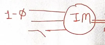
But do you think single phase will help in braking of IM? For that we need speed torque characteristics for this case.
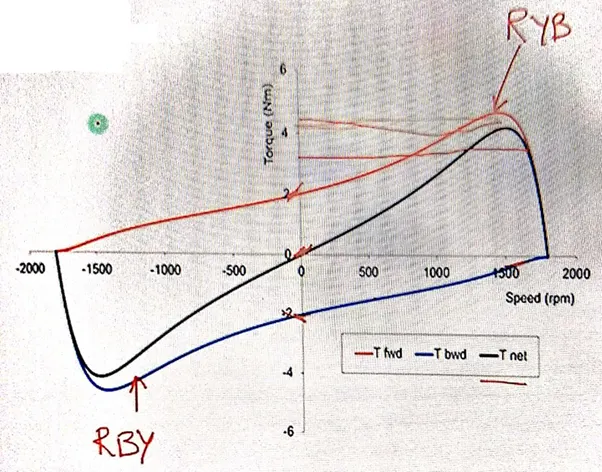
From the above characteristics, suppose the red curve is for RYB sequence and blue curve be for RBY sequence. The black curve is the net torque curve obtained fro deducting the RYB from RBY. This black curve is what applicable for single phase, since it is the result of any two phases among the 3 phases. Note that the black curve is passing through the centre (i.e. the starting torque for a single phasing IM is 0). It means that the single phased motors cannot be used as self-starters. and its torque value is continuously decreasing to 0 and then increasing in reverse direction. Hence braking phenomena happens.
OBJECTIVE -1 `to` For a defined driving cycle, calculate the energy required for braking.
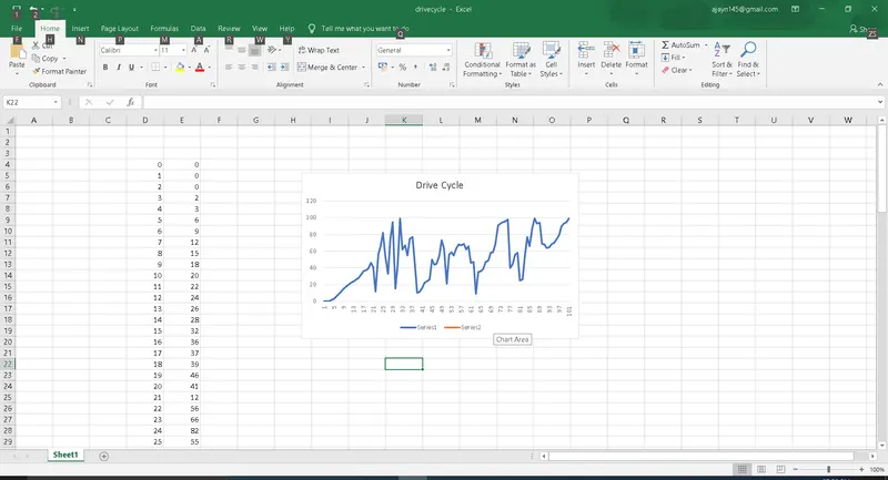
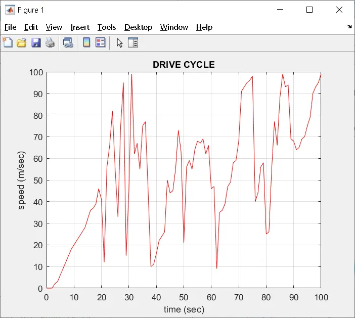
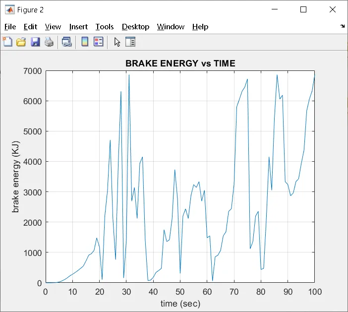
Here, i have defined a drive cycle with the file name "drivecycle" in txt format. I loaded the file ont the MATLAB. I assigned the first and second coloumn as time (sec) and speed (m/sec). Then plotted a graphical representation of drive cycle, along with that, calculated the brake energy. Atlast, plotted a brake energy vs time graph.
Drive cycle `to`
% Brake Energy Calculation For a Drive Cycle

clear all
close all
clc

load drivecycle.txt                                % drive cycle file
time = drivecycle(:,1);                            % assigning the first coloumn of the drive cycle as time values in sec
speed = drivecycle(:,2);                           % assigning the second coloumn of the drive cycle as speed values in m/sec

figure
plot(time,speed, 'Color','r')                                   % drive cycle graphically
title('DRIVE CYCLE')                               % title
hold on
xlabel('time (sec)')                               % labelling x axis
ylabel('speed (m/sec)')                            % labelling y axis
grid on                                            % making grids ON

kerb_weight = 1400;                                % vehicle mass in Kg

brake_energy = (0.5.*kerb_weight.*speed.^2)./1000;           % braking energy calculation

figure
plot(time,brake_energy)                                      % plotting brake energy vs time graph
grid on                                                      % making grids ON
title('BRAKE ENERGY vs TIME')
xlabel('time (sec)')                                         % labelling x axis
ylabel('brake energy (KJ)')                                  % labelling y axis
The corresponding output is as shown below -
OBJECTIVE -2 `to` Why electric motor can’t develop braking torque at high speed similar to starting? How electric and mechanical brakes are coordinated?
The below figure is a torque speed variation for a motor. As seenfrom the figure, we can confirm that the contour obtained is a mirror image. The contour lines above the partition is for the torque speed variation while acceleration. And below, it is for the deceleration or braking case.
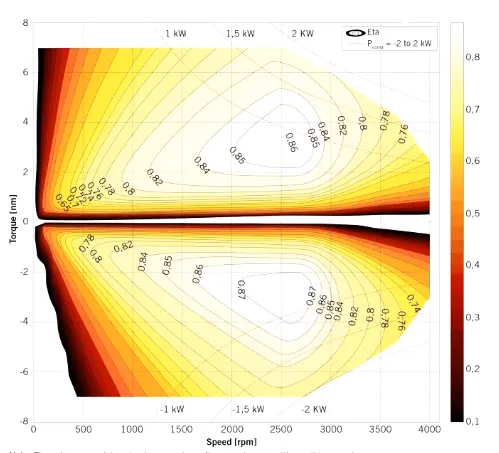
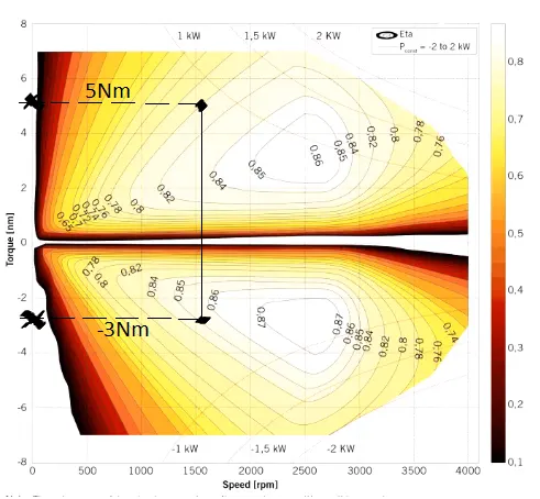
If we extrapolate a point in acceleration region and to the deceleration region, we find the corresponding torque is not sameas shown in the figure.
For eg:- Acceleration Torque = 5Nm
Braking Torque = -3Nm (i.e. not a -5Nm)
Hence, the braking torque is not same as that of acceleration torque. The reason would be that once the motor goes above the base speed, the torque is comprimised. At high speed the while applying the brakes, the brake torque is less compared to the acceleration torque. So we can say that for an EV the regenerative braking will not be effective, as the the current back to the battery whil braking will less compared to what the battery delivers while accelerating.
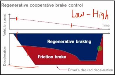
Now, if we have to coordinate between the mecanical and electric brakes, we will need a strategy to implement the effective brakes. The brake control strategies are of two types -
- Series - here one particular type of brake is applied one after the other (i.e. regenerative,then electric, regenerative, then electric...and so on)
- Parallel - this implements both the brakes at a time, simultaneously
we can again classify the strategies based on the comfort and energy recovery. For example, if we need more comfortability then we will get that that at the expense of energy. And if its the energy that we are focucing, then we have to comprimse on the comfortness.
case study on Nissan Leaf - Here, at low speed, the brake mostly shared by regenerative braking than the friction brakng. Similarly, at high speed it is a combined effort, probably a parallel strategy. The parallel strategy at high speed for will include pedal applied, followed by hydraulic and a regenerative braking.
OBJECTIVE -3 `to` Make a MATLAB program which plots contour of given motor speed, torque and efficiency values. Attach the code as a .m file attach a screenshot of all the plots
% PROGRAM TO PLOT CONTOUR LINES FOR THE DEFINED MOTOR SPEED, TORQUE AND EFFICIENCY

close all
clear all
clc

%SPEED & TORQUE ARRAY
w = linspace(1,1250,250);                 % SPEED ARRAY
T = linspace(1,100,250);                % TORQUE ARRAY

%MESHGRID
[X,Y] = meshgrid(w,T);                   % 2D COORDINATES FOR SPEED & TORQUE

%LOSS CONSTANTS
kc = 0.2;                                % COPPER CONSTANT
ki = 0.008;                              % IRON CONSTANT
kw = 0.00001;                            % WINDAGE CONSTANT
const = 20;                              % CONDUCTION CONSTANT

%MOTOR LOSS CALCULATIONS
l_copper = (Y.^2)*kc;                    % COPPER LOSS
l_iron = (X*ki);                         % IRON LOSS
l_windage = (X.^3)*kw;                   % WINDAGE LOSS

%OUTPUT POWER,INPUT POWER & EFFICICENCY CALCULATIONS
pout = X.*Y;                                            % OUTPUT POWER
pin = pout + l_copper + l_iron + l_windage + const;     % OUTPUT POWER
eff = pout./pin                                         % EFFICICNCY CALCULATION

%EFFICIENCY VALUES FOR CONTOUR
V = [0.70,0.80,0.85,0.90,0.91,0.92,0.925,0.93];         % DEFINES AN ARRAY FOR EFFICIENCY THE CONTOUR LIMITS

%COMMANDS FOR READABILITY
figure
box off                                                 % REMOVES THE BOX OUTLINE AROUND THE AXES
grid OFF                                                % GRIDS ARE NOT SHOWN
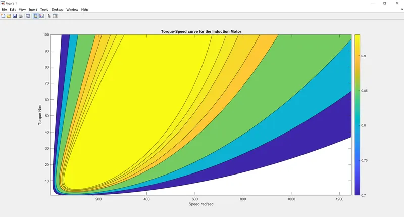
contourf(X,Y,eff,V);                                    % CONTOUR COMMAND
colorbar                                                % COLORBAR FOR BETTER UNDERSTANDING
xlabel('Speed rad/sec')                                 % X AXIS IS LABELLED
ylabel('Torque N/m')                                    % Y AXIS IS LABELLED
zlabel('Efficiency')                                    % Z AXIS IS LABELLED
title('Torque-Speed curve for the Induction Motor')     % TITLE OF THE PLOT

figure
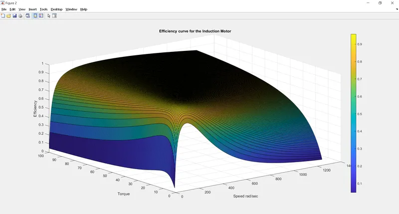
surf(X,Y,eff)                                           % SURFACE COMMAND
colorbar                                                % COLORBAR FOR BETTER UNDERSTANDING
xlabel('Speed rad/sec')                                 % X AXIS IS LABELLED
ylabel('Torque')                                        % Y AXIS IS LABELLED
zlabel('Efficiency')                                    % Z AXIS IS LABELLED
title('Efficiency curve for the Induction Motor')       % TITLE OF THE PLOT
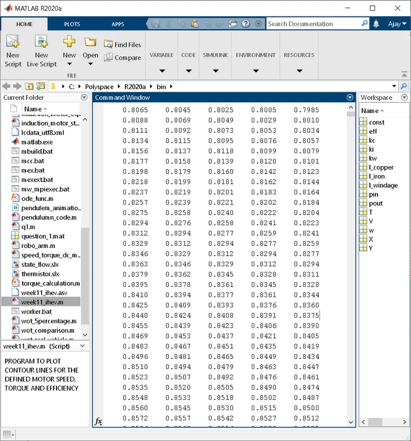
Here, i have defined arrays for speed and torque of the motor. Then they are plot in a 2D coordinate, using the command "meshgrid". Followed by the loss constants for calculating the losses occuring in the motor. These losses are used in calculating input and output power, followed by the efficiency of the motor. Then, the array "V" is defined with values equal to the efficiencies that we want to plot. Atlat the contour plot is defined. In the contour command, the variable, "eff" is defined as the function of "X" & "Y", followed by the "V" variable for plotting the efficiency contours.
MOTOR LOSSES `to`
- Copper Loss =`K_(CU)*(omega^2)`
- Iron Loss = `K_(FE)*(T^2)`
- Windage Loss = `K_(WINDAGE)*(T^3)`
- Conduction loss
OUTPUT `to`
GOOGLE drive `to` https://drive.google.com/drive/folders/1HxA7VOHd1KUh2H_VjEtprvaB_yZQ0ZZC?usp=sharing