Week-11 Challenge: Braking
TASK I
Calculate the energy required for braking for a defined driving cycle.
The law of conservation of energy, which states that energy cannot be generated or destroyed but only transformed into another form, is followed during the braking process.
`E=(1/2)xxM(Vi-Vf)^2`
Where,
m = Mass of the vehicle in Kg.
Vi = Initial speed of the vehicle in m/s.
Vf = Final speed of the vehicle in m/s
| Time (Sec) | Speed (Km/hr) |
| 0 | 0 |
| 1 | 0 |
| 2 | 0 |
| 3 | 1 |
| 4 | 3 |
| 5 | 6 |
| 6 | 8 |
| 7 | 10 |
| 8 | 12 |
| 9 | 14 |
| 10 | 16 |
| 11 | 17 |
| 12 | 19 |
| 13 | 20 |
| 14 | 22 |
| 15 | 24 |
| 16 | 25 |
| 17 | 26 |
| 18 | 27 |
| 19 | 29 |
| 20 | 30 |
| 21 | 28 |
| 22 | 25 |
| 23 | 23 |
| 24 | 21 |
| 25 | 19 |
| 26 | 17 |
| 27 | 15 |
| 28 | 10 |
| 29 | 5 |
| 30 | 4 |
| 31 | 2 |
| 32 | 1 |
| 33 | 0 |
Drive cycle of the above mentioning table
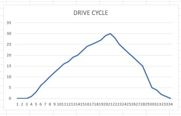
The energy or breaking can be calculated and is shown below. Also taken into account are the required assumptions.
| INPUTS | VALUES |
| Kerb Weight (Kg) | 1000 |
| Pay Load (Kg) | 200 |
| Initial Velocity (Km/hr) | 30 |
| Final Velocity (Km/hr) | 0 |
| Calculations | |
| Total Weight | 1200 |
| Total Mass | 122.324159 |
| Initial Velocity (m/Sec) | 8.333333333 |
| Energy for breaking (J) | 4247.366633 |
4.2 KJ is the breaking energy.
* The below is an Excel link for energy calculations.
TASK II
Mechanical Brake;
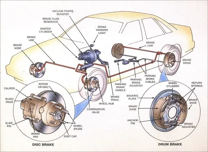
All mechanical brakes function by creating frictional forces as two surfaces collide. The frictional surfaces' surface area and the applied actuation force have a significant impact on a brake's stopping power or capacity. To slow down or stop shafts in equipment drives, mechanical brakes are assemblies made up of mechanical components. They transfer force from one location to another via levers or links. The connected shafts' movement is slowed or stopped by braking. The mechanical brakes come in a variety of varieties.
Electrical Brake;
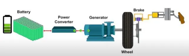
Electric brakes are devices that slow down or halt the rotation of a rotating component using an electrical current or magnetic actuation force. They are utilised in applications requiring quick response times and accurate tension control in both industrial and automotive braking systems. Two conductor wires on the magnet in the backing plate tap directly into the wiring. The brake magnet becomes magnetised when the electricity is on. The magnet is drawn to the surface of the drum. It rotates when it comes into touch with this area due to friction, which moves the actuating arm and forces the shoes up against the drum.These shoes are made of a unique brake pad material that withstands the heat produced by the friction. The hub and, as a result, the wheel that is touching the ground are prevented when the shoes press against the inside of the drum.
Regenerative Braking, an extremely attractive electric braking system, is presently used for electric braking. The motor acts as a generator in this instance during braking. As is well known, a counter torque is generated during the producing process. As a result, the motor stops moving due to the counter torque. Additionally, the energy from the brakes is transformed into electrical energy that can be sent back to the source via power converters.
Why can't an electric motor produce the same braking torque at high speed as it does when it starts?
In an electric vehicle, a motor-generator and battery pack are used to generate power. As electricity flows through the motor under a magnetic field, it produces force. The motor will spin faster the more current is applied.For regenerative braking, a motor will function as a generator, meaning that the flow of electricity is reversed; instead of drawing current to spin the armature, the armature is spun via the field by the vehicle's deceleration. The motor can switch between driving the vehicle and generating electricity as quickly as the driver can accelerate and take off. The electricity generated is used to recharge the battery.Back electromotive force, commonly known as back EMF, is produced as the motor's revs rise. The motor can generate a lower effective voltage the quicker it rotates because more back EMF is produced. At 0 RPM, however, all of the electricity that the motor generates at the moment electric power is delivered is transformed into instant torque—without any back EMF to lower its output. Since back EMF increases with rpm, the instantaneous torque effect decreases.
DC or AC While there is no torque at maximum speed, there is a steady drop in torque as the speed approaches maximum speed. Since the majority of the torque is used to boost the load's kinetic energy at the start of acceleration, this situation does not arise (and motor). However, it is impossible to create brake torque as well as raise the torque when the speed is already high and no additional load is provided. The motion in which the braking operation takes place is proportionally distributed between regenerative braking and brake energy.
Coordination of mechanical and electrical braking in EVs
A regenerative braking system uses a motor that, when turned around, functions as a generator to transform waste energy (heat) into useable energy (stored in a battery). There are some restrictions with regenerative braking system , one of which is that the electric motor can't deliver all the brake torque required for significant decelerations. If only one axle receives the braking torque during braking, stability and mobility problems may result. Regenerative braking is therefore used in conjunction with a friction (mechanical) brake system to prevent such a situation.
The mechanical brake and electronic brake are organised using two different types of brake control techniques.
- Series: Regenerative and mechanical braking are applied in series, one after the other.
- Parallel: Both mechanical and regenerative brakes are used at the same time.
The hydraulic fluid that reaches the brake pistons when the brake pedal is pressed exerts braking pressure on the wheels. Regenerative braking then uses that same kinetic energy to produce extra power through the use of a bi-directional motor that acts as a generator when braking.
Electric Driven Intelligent Brake
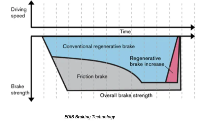
The Electric Driven Intelligent Brake, another world’s first system, utilizes the vehicle’s electric motor to directly operate the brake cylinders. When the driver steps on the brake pedal, the necessary braking force is maintained while the hydraulic pressure of the friction brake is controlled to help maximize the energy regeneration of the hybrid motor. Because of its simple structure, in which the motor directly operates the brake cylinders, this new Electric Driven Intelligent Brake system has the potential to be applied to various future hybrid vehicles.
Nissan’s goal is to achieve superior environmental performance while pursuing a fundamental quality of its cars – the joy of driving. The hybrid drive system to be used on the Fuga and Infiniti M Hybrids consists of the gasoline engine, electric motor and a unique Intelligent Dual Clutch Control utilizing separate electronically-controlled clutches on the drive wheels. This allows high environmental efficiency, while achieving an exhilarating driving experience with high-response linear acceleration levels that equal or exceed those of gasoline-powered cars.
TASK III
A MATLAB application that plots the contour of supplied values for motor speed, torque, and efficiency
The below is an matlab code(.m file) link for contour plot of motor efficiency.
In this MATLAB script, we use the 'linspace' tool to build arrays for the motor's speed and torque. Consider a range of values for the speed between 0 and 10,000 radians per second, and a range of values for the torque between 0 and 200 Nm. Using the'meshgrid' command, these arrays are then utilised to generate 2D grid coordinates. The contour plot will be made with the aid of these coordinates. We must take into account the numerous losses that occur during the motor's operation in order to determine the efficiency of the motor. As follows:
Copper losses
Iron losses
Windage losses
Conduction losses
The power of input and output is determined.
For the torque speed curves, a contour is plotted, and the command is used to map efficiency.
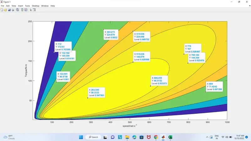
The motor's efficiency will decrease as speed increases.
Conclusion
With a certain diving cycle, breaking energy was estimated. Studies were done on the features of electric motors and how they relate to mechanical brakes. Also developed was a programme for contour plotting given motor speed, torque, and efficiency values.