Week-11 Challenge: Braking
___Q1___
AIM : To calculate the energy required for braking.
THEORY :
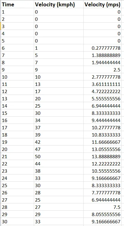
- A drive cycle is created in Excel file name - 'My Drive Cycle'.
- It is then read into Matlab for further calculations.
Energy required for braking is given by - `1/2*m.v^2`
= `1/2*m*(U-V)^2`
where, m = mass of vehicle.
v = velocity of vehicle.
U = Final Velocity.
V = Inititla Velocity.
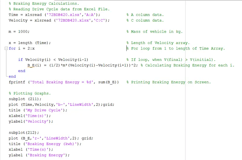
The Total Braking Energy is calculated using a Matlab program.
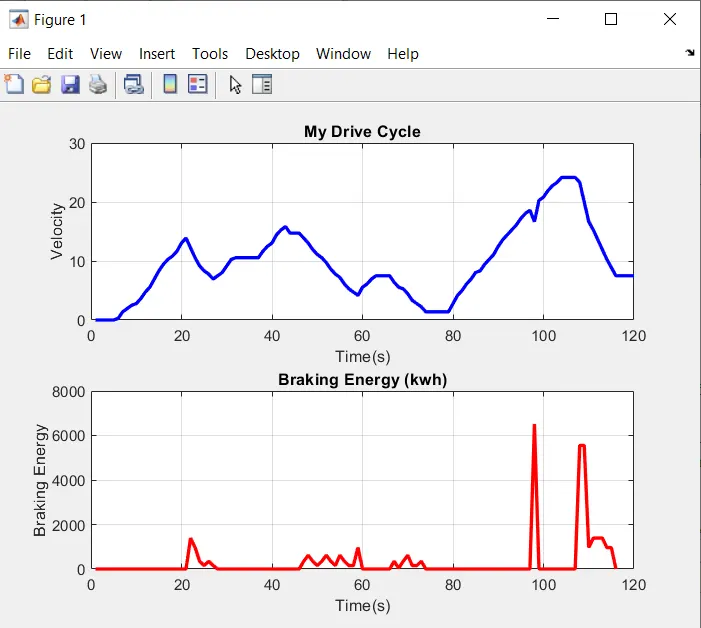
OUTPUT : From the plot we can see spike in Brake Energy graph when the Velocity decreases in My Drice Cycle graph.

CONCLUSION :
The total brake energy required for the given drive cycle is 35 kwh which is the sum total of the braking energy required during the whole cycle.
___Q2___
Why electric motor can’t develop braking torque at high speed similar to starting? How electric and mechanical brakes are coordinated?
Answer :
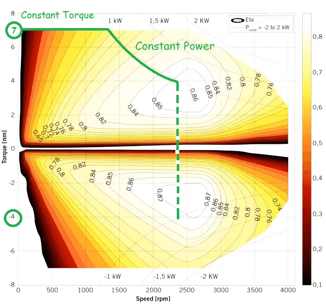
Above figure shows the Speed Torque Efficiency contour plot of motor.
During Acceleration : During low speed, Torque produced by the motor is almost constant.
Here the motor operates in constant torque region.
Hence higher acceleration power is possible in this region. Peak Torque = 7 Nm.
During Deceleration : At the instant of braking, the motor speed is high.
Here it operates is constant power region.
The curve shifts towards braking region and the torque is negative. Peak Torque = -4 Nm.
Therefore the motor cant develop braking troque at high speed.
Electrical (regenerative) and mechanical (friction) brakes are coordinated with brake control strategies.
1- Series Connection : where both brakes are applied one after the another. So either of the brake is applied at an instant.
Further classified depending upon Brake Behaviour (comfort of driver) or Energy Efficiency.
The friction brakes operates only when the regenerative brake has reached its maximum, which is lower than that requested by the driver.
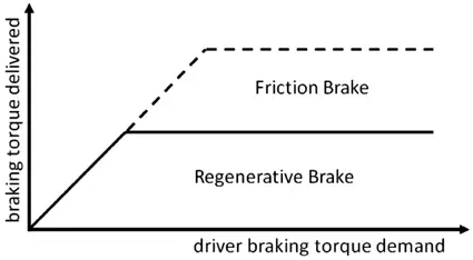
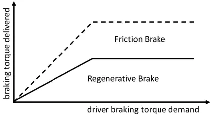
2- Parallel Connection : where both brakes are applied simultaneously.
___Q3___
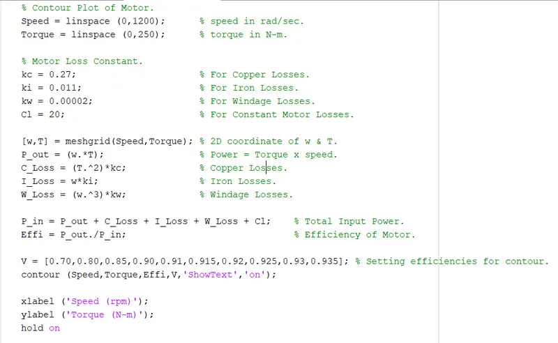
AIM : To plot contour of motor speed, torque and efficiency values.
GIVEN :
Parameters- Motor Loss Constants.
For Copper Losses. kc = 0.27;
For Iron Losses. ki = 0.011;
For Windage Losses. kw = 0.00002;
For Constant Motor Losses. Cl = 20;
THEORY :
To calculate efficiency of a motor, various losses needs to be considered.
Copper Losses :- `I^2R` losses, where R is armature resistance & I is the current through it.
Since torque is proportional to Current, C_Loss`= k_c.T^2`
Where `k_c`is constant of copper loss.
Iron Losses :- These are magnetic losses, dependent on speed.
At different speed motor has different back emf and hence the iron losses changes.
I_Loss = `k_iomega`, where `k_i`is iron loss constant.
Windage Losses :- Due to friction and windage. W_Loss = `k_womega^3`
Constant Losses :- Cl.
Total losses = Copper + Iron + Windage + Constant Loss.
= `k_cT^2 + k_iomega + k_w omega^3 + C_l`
Matlab Code :-
OUTPUT :
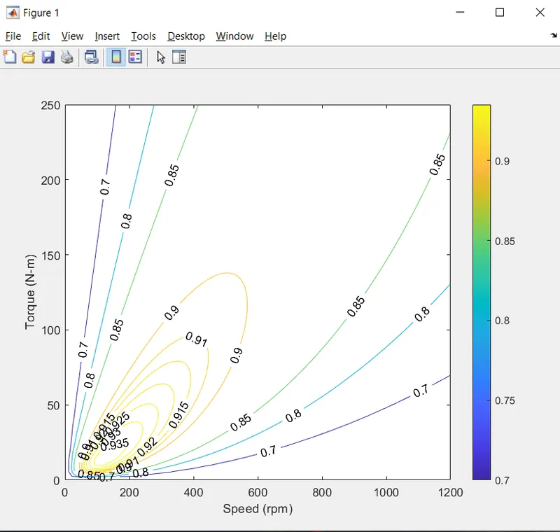
From the plot we can see that the area under 90% efficiency is low with torque produced around 140 N-m at speed upto 600 rpm.