Week-11 Challenge: Braking
1. For a defined driving cycle, calculate the energy required for braking.
Answer:-
To calculate the amount of energy for braking the vehicle, let us understand first what is braking energy of vehicle,
Braking is an energy recovery mechanism that slows down a moving vehicle or object by converting its kinetic energy or potential energy into a form that can be either used immediately or stored until needed. The function of the braking system is to retard the speed of the moving vehicle or bring it to rest in the shortest possible distance whenever required. The vehicle can be held on an inclined surface against the pull of gravity by the application of a brake. Brakes are mechanical devices for increasing the frictional resistance that retards the turning motion of the vehicle wheels. It absorbs either kinetic energy or potential energy or both while remaining in action and this absorbed energy appears in the form of heat.
So, normally we called braking of vehicle is a Deacceleration.
Energy is required to accelerate the vehicle and same energy is required the deacceleration the vehicle which is
Energy = 1/2 mv2
Unit of electrical energy is Watt/H
With this fundamental equation we not consider the time for braking because we are not calculating the power we are only calculating the energy.
Example :- Find the braking energy of a vehicle from given values
M = 1000kg
Vi = 100 kmph (initial velocity)
Vf = 0 kmph (final velocity)
Kwh = ?
For above calculation we used a excel calculator
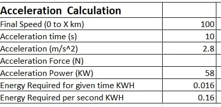
Above excel calculator results energy required for 10 sec is 0.016
So, energy is required for 1 sec is 0.16 KWH.
Now we are going to calculate the energy of Drive Cycle.
Drive Cycle:- (Sheet attached)
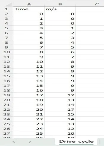
Energy calculation for given Drive Cycle
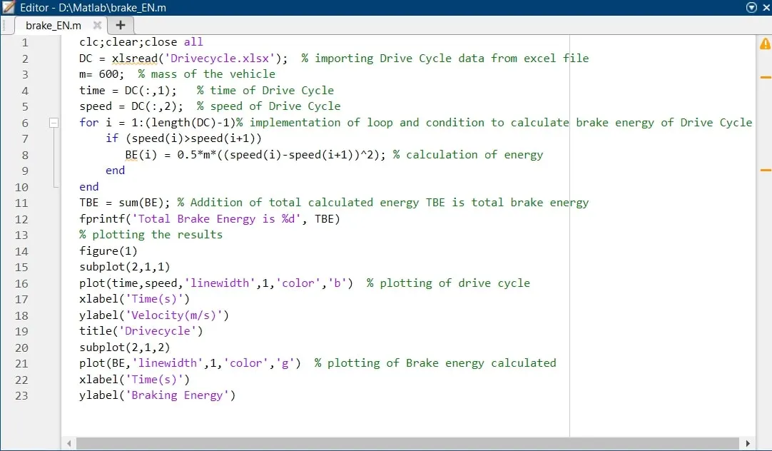
KE = 0.5*m*v^2
To calculate the energy for given Drive Cycle we are going to use a MATLAB script.
Plotting Result :-
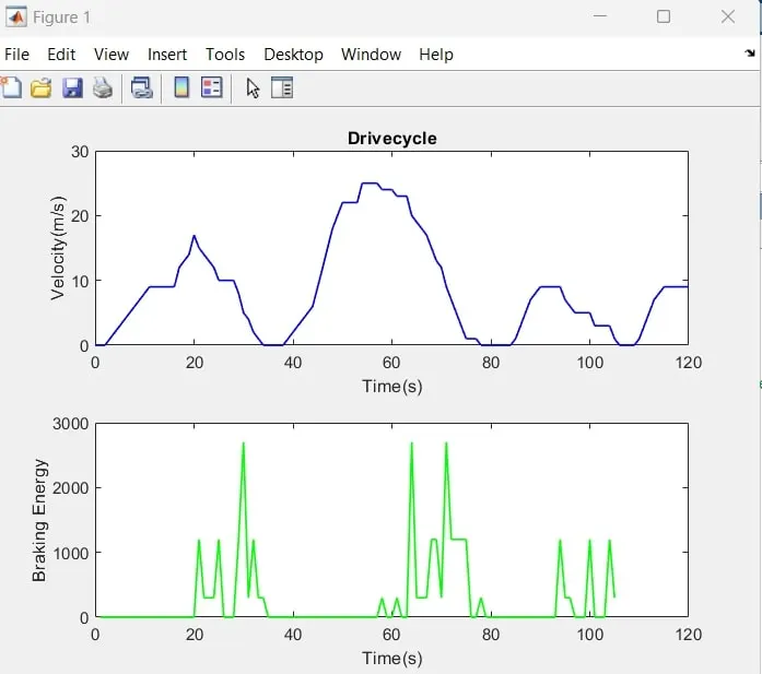
Result on command window
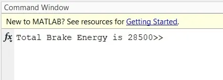
2. Why electric motor can’t develop braking torque at high speed similar to starting? How electric and mechanical brakes are coordinated?
Answer:-
Electric motors are unable to develop braking torque at high speeds similar to starting torque because of the following reasons:
(a) Braking torque direction
Braking torque is applied in the opposite direction of the motor's rotation.
(b) Flux weakening effect
When the electric supply is removed from the motor, it acts as a generator, which produces low torque due to the flux weakening effect.
(c) Motor efficiency
As the motor's efficiency increases, the speed and torque required to overcome motor losses decreases.
(d) Power converter
The power converter's efficiency decreases at low speeds, which reduces regenerative braking.
Electric Braking :-
Electric brakes are devices that use an electrical current or magnetic actuating force to slow or stop the motion of a rotating component. They are used in industrial and vehicular braking applications that require fast response times and precise tension control.
Regenerative Braking of DC motor :-
Regenerative braking is a mechanism that slows a vehicle down while converting its kinetic energy into electricity. This electricity can be used to charge a vehicle's battery, or stored for later use. Regenerative braking is common in hybrid and electric vehicles, but can also be found in some modern petrol and diesel cars.
Regenerative braking is a unique technique that is used in EVs to capture energy that the vehicle has due to its motion or, in other words, its kinetic energy that would have been wasted when the vehicle decelerates or comes to a standstill while braking.
Typically, regenerative brakes work by driving an electric motor in reverse to recapture energy that would otherwise be lost as heat during braking, effectively turning the traction motor into a generator. Feeding power backwards through the system like this allows the energy harvested from deceleration to resupply an energy storage solution such as a battery or a capacitor. Once stored, this power can then be later used to aid forward propulsion. Because of the electrified vehicle architecture required for such a braking system, automotive regenerative brakes are most commonly found on hybrid and electric vehicles.
Mechanical Braking :-
Mechanical brakes use friction to slow or stop moving systems, such as wheels, axles, or vehicles. They work by absorbing energy and converting it to heat.
Mechanical braking system:It is the type of braking system in which the brake force applied on the brake pedal is carried to the final brake drum or disc rotor by the various mechanical linkages like cylindrical rods, fulcrums, springs etc. In order to stop the vehicle.
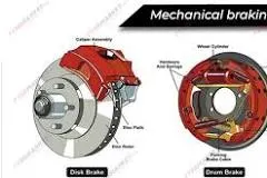
Coordination of Mechanical and Electrical Braking :-
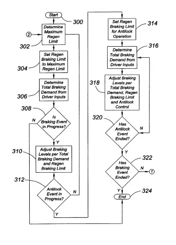
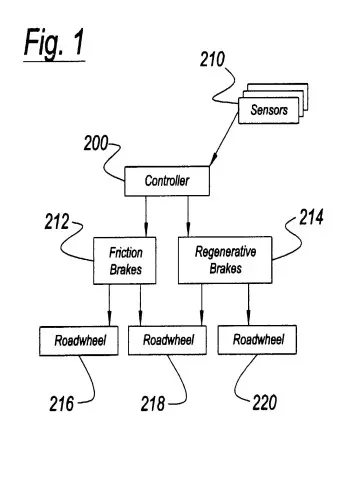
A regenerative brake (electrical braking) and mechanical brake combination system uses a combination of regenerative braking and hydraulic brakes to provide braking force to the vehicle to stop.
A combined regenerative and friction braking system for the road wheels of a vehicle includes a friction braking subsystem, a regenerative braking subsystem coupled to the road wheels equipped with the friction braking subsystem, and a brake system controller for controlling both the friction and regenerative braking subsystems such that regenerative braking is restored to a maximum practicable value following conclusion of an antilock braking event.
A method of operating friction and regenerative braking subsystems in a vehicle following the end of an ABS event, wherein a regenerative braking limit for an axle is first set to approximate the total braking torque developed by the friction and regenerative brakes associated with the axle as the ABS event ends, with the regenerative braking torque thereafter being increased, but not decreased, in accord with the total brake torque assigned to that axle according to the driver's braking demand and the requirements of balanced braking following the ABS event.
A combined regenerative and friction braking system for the road wheels of a vehicle includes a friction braking subsystem, a regenerative braking subsystem coupled to the road wheels equipped with the friction braking subsystem, and a brake system controller which operates the braking subsystems in an antilock mode, as required. The brake system controller controls and operates both the friction braking subsystem and the regenerative braking subsystem such that operation in the antilock operating mode will be followed by a period of operation in which the maximum braking torque applied by the regenerative braking subsystem to a particular axle is limited to a level comparable to the maximum braking torque applied by the friction braking subsystem as well as by the regenerative braking system as a period of antilock operation ends. The brake system controller operates the regenerative braking subsystem so as to restore regenerative braking torque up to a maximum value as quickly as possible. In essence, the regenerative braking torque limit is ratcheted up to a maximum value in accord with the total brake torque generated by the regenerative and friction brakes on the axle.
3. Make a MATLAB program which plots contour of given motor speed, torque and efficiency values. Attach the code as a .m file attach a screenshot of all the plots.
Answer:-
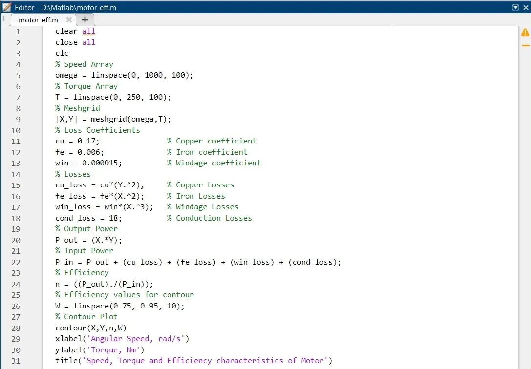
MATLAB script for motor speed, torque and efficiency.
Description:-
In this MATLAB script, we create arrays for the speed and the torque of the motor using the ‘linspace’ command. For the speed, consider a range of values from 0 to 2000 radians per second whereas for the torque, consider a range of values from 0 to 300Nm. These arrays are then used to create 2D grid coordinates using the ‘meshgrid’ command. These coordinates will help in the creation of the contour plot. To find the efficiency of the motor, we need to consider the various losses that occur in the motor’s operation. These are:
- Copper losses
- Iron losses
- Windage losses
- Conduction losses
These various losses are dependent on the speed and the torque of the motor. They each also have a characteristic constant of proportionality which are all assumed for the following calculations and represented as 'K'. In each calculation, the speed and the torque are represented respectively as ω and T.
- Copper losses = KCu⋅ω2
- Iron losses =KFe⋅T2
- Windage losses =Kw⋅T3
The values of coefficients are taken as general values. Conduction losses are assumed to be 18 Joules.
Plotting result
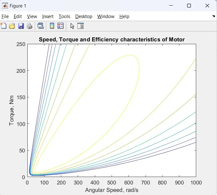
From this contour plot, we can see that the highest level of efficiency arises in the innermost contour plot and this efficiency decreases as the contours increase in size from the innermost contour.