Week-11 Challenge: Braking
Objectives of Challenge 11 Assignment:
- For a defined driving cycle, calculate the energy required for braking.
- Why electric motor can’t develop braking torque at a high speed similar to starting? How electric and mechanical brakes are coordinated?
- Make a MATLAB program which plots the contour of given motor speed, torque and efficiency values. Attach the code as a .m file and attach a screenshot of all the plots.
***************************************************************************
Q) For a defined driving cycle, calculate the energy required for braking?
A)
Computing the energy expected for braking of UDDS Drive Cycle-
Braking: Braking is a condition to dial back or stop a moving vehicle as required. There are a few methods to apply brakes, which can be mechanical or electrical. The most generally utilized procedure is by applying to rub. It consumes energy The consumed dynamic Energy can be determined as the following condition
Braking Energy = (1/2) *m*v^2
Where,
- Braking Energy is the dynamic energy in the unit of Joule.
- m= Total Mass of the Vehicle (Vehicle Mass + Pay Load) in the unit of Kilogram.
- v= (Initial Velocity-last Velocity) in unit m/s.
For Example on the off chance that the initial speed of a vehicle is 90m/s and the last speed is 70m/s. The mass of the vehicle is 1500kg. Then, at that point, the required dynamic energy for Braking is
(1/2)*1500*(90-70) ^2 = 300000 J = 300KJ
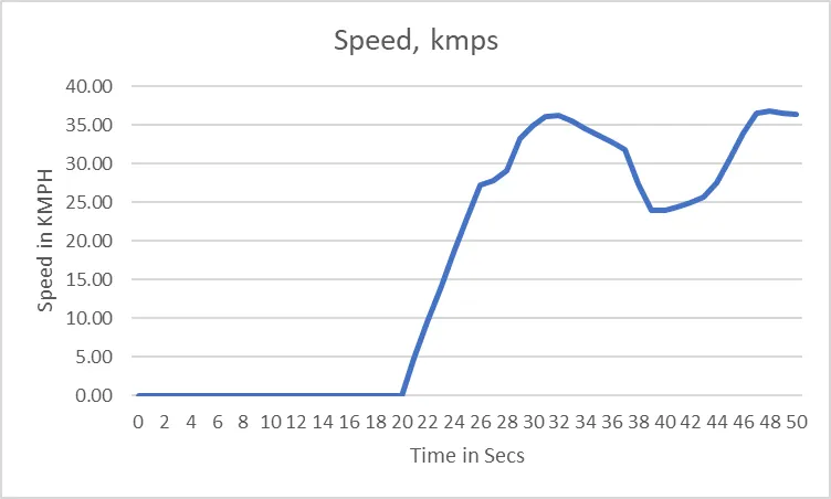
Here for a Drive cycle, the required braking energy is determined for each second of time to dial back or stop the vehicle-Braking Energy Calculation for UDDS Driving Cycle.
| UDDS | ||
| Time, secs | Speed, mph | Speed, kmps |
| 0 | 0 | 0.00 |
| 1 | 0 | 0.00 |
| 2 | 0 | 0.00 |
| 3 | 0 | 0.00 |
| 4 | 0 | 0.00 |
| 5 | 0 | 0.00 |
| 6 | 0 | 0.00 |
| 7 | 0 | 0.00 |
| 8 | 0 | 0.00 |
| 9 | 0 | 0.00 |
| 10 | 0 | 0.00 |
| 11 | 0 | 0.00 |
| 12 | 0 | 0.00 |
| 13 | 0 | 0.00 |
| 14 | 0 | 0.00 |
| 15 | 0 | 0.00 |
| 16 | 0 | 0.00 |
| 17 | 0 | 0.00 |
| 18 | 0 | 0.00 |
| 19 | 0 | 0.00 |
| 20 | 0 | 0.00 |
| 21 | 3 | 4.83 |
| 22 | 5.9 | 9.50 |
| 23 | 8.6 | 13.84 |
| 24 | 11.5 | 18.51 |
| 25 | 14.3 | 23.01 |
| 26 | 16.9 | 27.20 |
| 27 | 17.3 | 27.84 |
| 28 | 18.1 | 29.13 |
| 29 | 20.7 | 33.31 |
| 30 | 21.7 | 34.92 |
| 31 | 22.4 | 36.05 |
| 32 | 22.5 | 36.21 |
| 33 | 22.1 | 35.57 |
| 34 | 21.5 | 34.60 |
| 35 | 20.9 | 33.64 |
| 36 | 20.4 | 32.83 |
| 37 | 19.8 | 31.86 |
| 38 | 17 | 27.36 |
| 39 | 14.9 | 23.98 |
| 40 | 14.9 | 23.98 |
| 41 | 15.2 | 24.46 |
| 42 | 15.5 | 24.94 |
| 43 | 16 | 25.75 |
| 44 | 17.1 | 27.52 |
| 45 | 19.1 | 30.74 |
| 46 | 21.1 | 33.96 |
| 47 | 22.7 | 36.53 |
| 48 | 22.9 | 36.85 |
| 49 | 22.7 | 36.53 |
| 50 | 22.6 | 36.37 |
***************************************************************************
Q) Why electric motor can’t develop braking torque at a high speed similar to starting? How electric and mechanical brakes are coordinated?
A)
Sometimes after accelerating you can't reach the maximum torque. The reason is that no matter how much the current loop wants to increase current (proportional to torque) by increasing the PWM duty cycle of the power stage, the V motor is too close to Vbemf and therefore current can't increase more.
Whenever Friction torque + Additional loads = Motor Torque, the load remain in equilibrium (does not move, or moves under constant speed). Whenever Friction torque + Additional loads < Motor Torque, the load accelerates (Motor torque - Friction torque - Additional loads = Acceleration torque > 0). Al high speeds, the BEMF is so close to Vbus that the applicable Motor torque gets limited. Then, the bigger the Friction torque + Additional load is, the smaller the Acceleration torque becomes.
This can also occur if acceleration or speed is limited for some reason.
This situation does not occur at the beginning of acceleration because most of the torque is used to increase the kinetical energy of the load (and motor). But when the speed is already high and no extra load is applied it is not possible to increase the torque.
Maximum achievable torque depending on motor speed
Recalculate this based on your motor parameters.
How to prevent this
Increase DC bus voltage.
Unlimited system acceleration.
Use a motor with less resistance and lower back EMF proportion.
Compensation for electric mobility throttles
This situation creates a bad feeling that at high speeds the throttle does not work correctly.
The user feels that it releasing the throttle does not reduce motor force!
The proposed solution is to add a torque demand limitation based on speed.
- Will improve user feeling when releasing the brake when the vehicle is already accelerated.
- Will limit vehicle top speed (safety)
TYPES OF BRAKING SYSTEMS:
- MECHANICAL BRAKING:
- Drum braking
- Circle braking
- Band braking
- Pawl and Ratchet braking
- ELECTRICAL BRAKING:
- Plugging type braking
- DC injection type braking
- Eddy current braking
- Dynamic resistor type braking
- Regenerative braking
- Sharing DC bus-type braking
MECHANICAL BRAKING SYSTEM:
Mechanical braking is generally utilized in bikes, engine vehicles, and motorcycles where little power is required. It is fundamental in assembling power transmission applications, material taking care of, and so forth. It conveys powers to the hub or a wheel to stop movement. It assists with diminishing the speed of the framework gradually by the mechanical cycle when contrasted with electrical braking. The working of a mechanical brake relies upon the pedal. At the point when the pedal is squeezed, the brake shoes are pushed outwards and pivot against the drum which is associated with the wheels, Subsequently, the machine or vehicle gets delayed down and halted. Also, when the pedal is delivered, it goes to the typical position because of the pullback activity of spring shoes.
ELECTRICAL BRAKING SYSTEM:
Electrical braking is utilized to decrease the speed of the machine contingent upon transition and force. This type of braking is primarily utilized for utilitarian braking to control the speed of the machine. It is not difficult to deal with and agreeable. However, it can't be utilized for crisis braking and stopping braking. The working of electrical braking relies upon the electromagnetic power (EMF) following up on the brake shoes. The battery is utilized to create an electric current which assists with empowering the electromagnet mounted on the backplate. This outcome in actuating the cam and growing the brake shoes. Subsequently, the vehicle or machine is come by braking the wheel.
REGENERATIVE BRAKING SYSTEM:
It is one of the types of electrical braking framework. At the point when the speed of the engine is expanded than the simultaneous speed, then the regenerative braking is utilized. At the point when the rotor turns higher than the speed of the coordinated speed, then, at that point, the engine goes about as a generator and the headings of the current stream and the force are turned around. Consequently, the generator is come by braking. The fundamental detriment is, that the point at which the engine surpasses the coordinated speed, it is conceivable mechanical and electrical harm. In this way, regenerative braking should be possible at the sub-coordinated speed just when the variable recurrence source is applied. An inverter is utilized to bring the overabundance back energy back to the three-stage supply as opposed to the dissemination of energy in the resistor. To drive the variable recurrence frameworks, an inverter is associated in lined up with the rectifier. Regenerative braking is for the most part utilized in electric vehicles.
PLUGGING TYPE BRAKING SYSTEM:
It is additionally one of the types of electro braking framework. In this type, the pedal is utilized for braking the vehicle. At the point when the pedal is squeezed, the speed of the electric vehicle is diminished by changing the extremity and heading of the engine. The heading of the engine gets switched and in turn, causes braking of the wheel. In generators, the utilization of the plugging type braking framework brings about diminished speed because of the inversion of terminals of the stock, inversion of force, and limitation of turn of the engine. An outer resistor is utilized to restrict the current streaming through the plugging circuit. The more power is squandered during the plugging.
DYNAMIC BRAKING SYSTEM:
It is otherwise called dynamic resistor braking or dynamic rheostat braking. In this type, the opposition is given to the engine by the rheostat associated with the circuit is fit for a speed increase or deceleration of the vehicle. This obstruction assists with diminishing the speed and stops the electric vehicle. The resistor or rheostat in the circuit disseminates overabundance energy on the capacitor by interfacing a resistor lined up with the capacitor. At the point when the engine goes about as a generator, switch current courses through the circuit, and the force changes furthermore, causing braking. The opposition in the circuit can be eliminated to keep up with the consistent force while braking the engine.
Water-powered BRAKING SYSTEM:
The water-powered braking framework involves fluid as a tension for the development of power or to increment the power. The tension applied to a fluid can be called water-driven pressure. This type of braking framework chips away at the standard of pascal's regulation. In this type, when the power is applied on the pedal, it is changed over completely to water-driven pressure by utilizing an expert chamber/fluid. This water-driven pressure helps in braking the vehicle by moving strain to the last brake drum or circle rotor by means of braking lines. It guarantees that the braking impact is similar on all four/two wheels. Rather than utilizing brake liquids, water-powered brakes are utilized to speed up or halt the vehicle. It is generally utilized in a wide range of bicycles and vehicles in view of their viability, the most noteworthy break creating force limit.
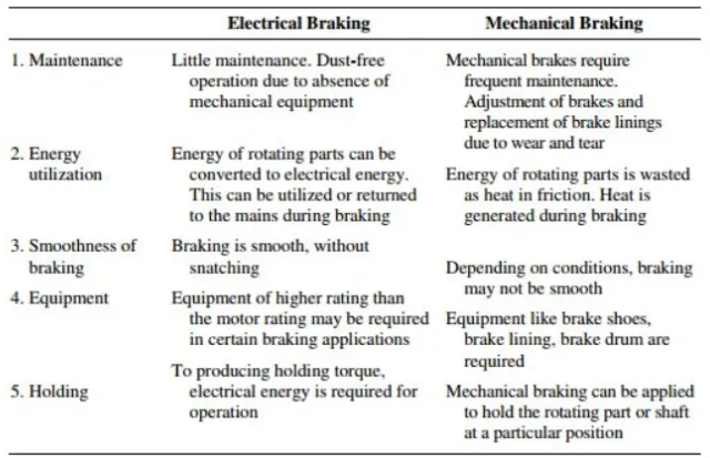
Correlation among Electrical and Mechanical Braking Systems:
- Electrical braking frameworks are utilized for practical braking (controlling the speed; carrying the heap to halt), and Mechanical braking frameworks are utilized for crisis halting or for stopping.
- Electrical braking is typically extremely smooth and agreeable. Mechanical braking is generally harsh and awkward.
- No wear results from electrical braking. Mechanical braking then again causes wear in the braking y parts and requires customary support.
- It is conceivable (however not generally attainable) in electrical braking frameworks to get the recovered energy once again to the primary supply. This is beyond the realm of possibilities in mechanical braking frameworks and the energy is constantly lost as intensity, clamour and wear.
- The electrical braking framework can't be utilized as a security gadget. Most frameworks will require a mechanical braking framework as a reinforcement wellbeing gadget.
***************************************************************************
Q) Make a MATLAB program which plots the contour of given motor speed, torque and efficiency values. Attach the code as a .m file and attach a screenshot of all the plots?
A)
%%%%%%%%%%%%%%%%%%%%%%%%%%%%%%%%%%%%%%%%%%%%%%%%%%%%%%%%%%%%%%%%%%%%%%%%%%%%
%% ploting the contour of given motor speed, torque and efficiency values %%
%%%%%%%%%%%%%%%%%%%%%%%%%%%%%%%%%%%%%%%%%%%%%%%%%%%%%%%%%%%%%%%%%%%%%%%%%%%%

%%%%%%%%%%%%%%%%%%%%%%%%%%%%%%%%%%%%%%%%%%%%%%%%%%%%%%%%%%%%%
%% Defining the speed and torque of the motor as an arrays %%
%%%%%%%%%%%%%%%%%%%%%%%%%%%%%%%%%%%%%%%%%%%%%%%%%%%%%%%%%%%%%

x = linspace(1,1000);           % Motor Speed in rad/sec
y = linspace(1,250);            % Motor Torque in N-m

%%%%%%%%%%%%%%%%%%%%%%%%%%%%%%%%%%%%%%%
%% Defining the Motor loss constants %%
%%%%%%%%%%%%%%%%%%%%%%%%%%%%%%%%%%%%%%%

Kc = 0.2;                       % Copper loss constant
Ki = 0.008;                     % Iron loss constant
Kw = 0.00001;                   % Windage loss constant
ConL = 20;                      % Constant motor loss
%%%%%%%%%%%%%%%%%%%%%%%%%%%%%%%%%%%%%%%
%% Defining the Motor loss equations %%
%%%%%%%%%%%%%%%%%%%%%%%%%%%%%%%%%%%%%%%
[X,Y] = meshgrid(x,y);          % To create a 3D array
Output_power = (X.*Y);          % Power equation
C_L = (Y.^2)*Kc;                % Copper loss equation
I_L = (X*Ki);                   % Iron loss equation
W_L = (X.^3)*Kw;                % Windage loss equation

%%%%%%%%%%%%%%%%%%
%% Calculations %%
%%%%%%%%%%%%%%%%%%

Input_power = Output_power + C_L + I_L + W_L + ConL;
Z = Output_power./Input_power;    % Efficiency
V = [0.7,0.8,0.85,0.9,0.91,0.92,0.925,0.93];

%%%%%%%%%%%%%%%%%%%%%%%%%%
%% Plotting the Contour %%
%%%%%%%%%%%%%%%%%%%%%%%%%%

contour(X,Y,Z,V);
colorbar
xlabel('Speed of Motor (rad/sec)','Fontweight','Bold');
ylabel('Torque of Motor (N-m)','Fontweight','Bold');
zlabel('Efficiency','Fontweight','Bold')
title('Contour of given motor speed, torque and efficiency values','Fontweight','Bold')
legend('0.7,0.8,0.85,0.9,0.91,0.92,0.925,0.93')
grid off
box off

figure
surf(X,Y,Z)
colorbar
xlabel('Speed of Motor (rad/sec)','Fontweight','Bold');
ylabel('Torque of Motor (N-m)','Fontweight','Bold');
zlabel('Efficiency','Fontweight','Bold')
title('Contour of given motor speed, torque and efficiency values','Fontweight','Bold')
An efficiency guide of an electric motor is a contour plot of force and speed. It is utilized to depict the speed and force mixes expected at various efficiency ranges. To display the efficient contour we should
consider the losses that happen in electric motors and these losses are,
- Iron or Core Losses: Iron losses are made of two parts which are hysteresis and whirlpool flows. Hysteresis losses happen as we switch the electromagnets in our motor on and off, and rely upon the attractive properties of the iron material utilized in the motor. Vortex current losses rely upon numerous variables, including the thickness of the covers in the stator, the recurrence at which the motor works, the transition thickness and the material's resistivity. The iron losses are corresponding to the square of the overlay thickness.
- Copper or Variable Losses: Copper losses are because by the obstruction of the copper channels and the current that we request that they convey, and they lead to the warming of the guides. Obviously, in light of the fact that copper is weighty, we need to use a bit of it as could really be expected, limiting the cross-sectional region. This increments obstruction and subsequently expands losses and warming.
- Windage Losses: The misfortune brought about via air grinding among rotors and encompassing air is called windage losses. It occurs because of air protection from the armature. Higher the speed of the motor will be the windage losses.
Clarification of the code:
- First the reasonable all, nearby all and clc orders are composed to clear all variables in the work area, to clear all plots furthermore, and to separately clear the work area.
- The speed and force are characterized as 2-Dimensional straightly divided exhibits utilizing the linspace order.
- The constants of the motor losses are characterized.
- The 2-D varieties of speed and force are then characterized as 3-Dimensional exhibits utilizing the mesh grid order.
- The result power condition is characterized as the result of speed and force.
- The conditions of the motor losses in view of the speed and force are characterized.
- The information power is characterized as the amount of result power in addition to motor losses.
- The efficiency is then characterized as the proportion of the result's ability to enter power.
- To plan the contour for various efficiency runs a cluster is characterized which comprises the efficiencies from 0.7 to 0.93.
- The chart is plotted to utilize the contour order to plot the speed, force, and efficiency.
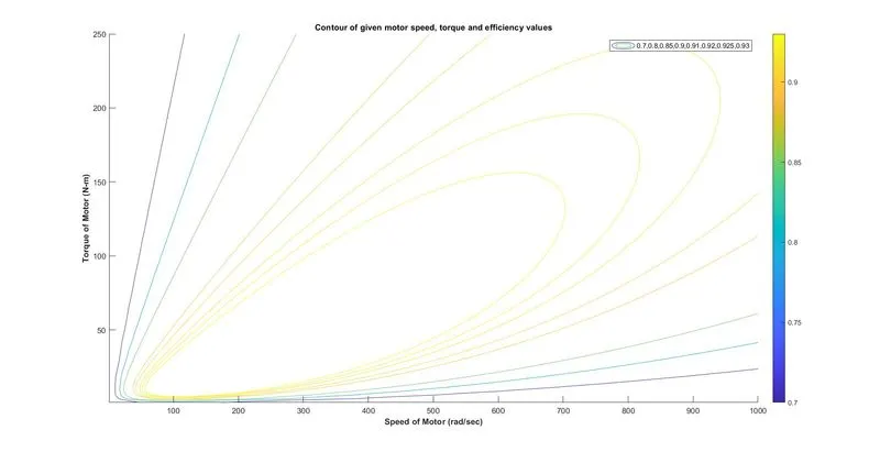
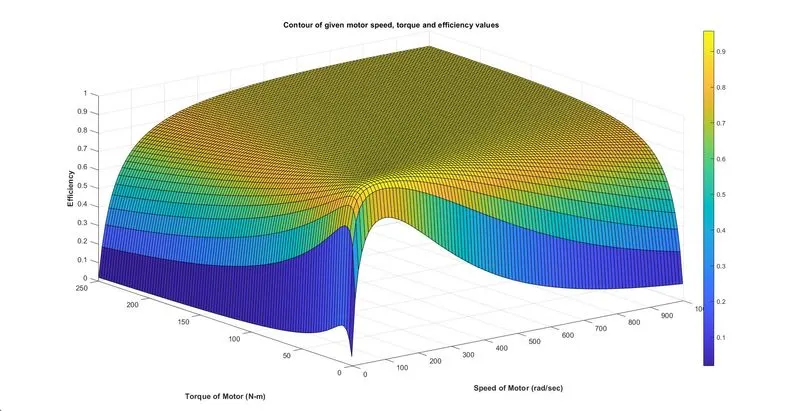
The contour plot of the above MATLAB program is given beneath:
From the plot, it very well may be seen that the speed and force change as the efficiency increments. This is expected to the motor losses that happen. The dull blue line address the contour with 70% efficiency and the dazzling yellow line addresses the contour with 93% efficiency. For instance, at 70% efficiency, the force arrives at its pinnacle worth of 250 N-m when the vehicle is at an exceptionally low speed however the force diminishes essentially as the speed increments for a similar efficiency. Furthermore, at a motor efficiency of 93%, the speed and force required are substantially less contrasted with an efficiency of 70%. More noteworthy is the motor efficiency, a lower speed-force blend is expected to conquer the motor losses.
The Conclusion:
The energy expected for slowing down of a vehicle in light of a drive cycle is determined. The coordination between electric brakes and mechanical brakes and why slowing down force is less at high
speed are made sense. The MATLAB program to plot the speed, force and efficiencies contour is composed and the chart is plotted.