Week-11 Challenge: Braking
Objective -
To calculate the energy required for braking for a defined driving cycle.
Theory -
Drive Cycle -
- A drive cycle is typically represented by a series of data points which plots vehicle speed against time.
- Here we have the data in the form of excel sheet.
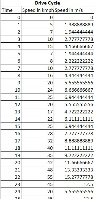
This excel sheet link is - Google Drive link of drivecycle.xlsx
Braking Energy -
- Braking is the process of controlling the velocity of an object by inhibiting its motion.
- An object in motion possesses kinetic energy and to bring the object to a stop this kinetic energy must be removed.
- Brake energy can be calculated as
`K_e =1/2mv_1^2−1/2mv_2^2`
MATLAB CODE -
clear all
clc
close all

m = 1000;
% xlsread(drivecycle.xlsx)
t = drivecycle(:,1);
v = drivecycle(:,3);
for i = 1:(length(drivecycle)-1)
    if v(i) > v(i+1)
        BE(i) = 0.5*m*(v(i) - v(i+1))^2; % Brake Energy
    end
end
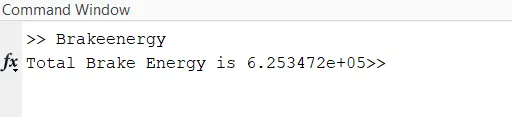
fprintf('Total Brake Energy is %d',sum(BE));
% Plotting
plot(BE,'color','r');
xlabel('Time(s)');
ylabel('Energy(J)');
title('Breaking Energy')
Results -
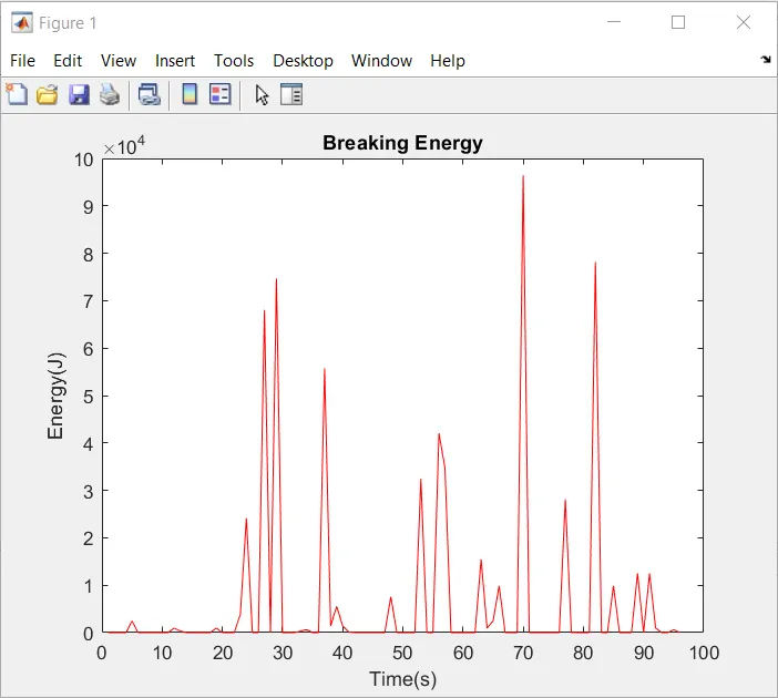
--------------------------------------------------------------------------------------------------------------------------------------------------------
Objective -
To discuss about
- Why electric motor can’t develop braking torque at high speed similar to starting?
- How electric and mechanical brakes are coordinated?
Theory -
Electric Motor Braking Torque limitations -
- In electric motor, regenerative braking is used.
- Regenerative braking allows electric vehicle to use the motor as a generator.
- When the brakes are applied the kinetic energy of vehicle is changed into electric energy and stored in the energy storage system.
- The regenerative braking torque produced is not enough to provide all the required braking torque of the vehicle.
- If it is made high it might cause unstability in the vehicle.
- The acceleration torque of motor is much higher than decceleration torue.
- At high speed, the motor may be in constant power regions.
- In this region the produced torque value are less and this also limits the amount of braking torque.
- These are reasons why electric motor can't develop braking torque at high speed similar to starting.
Electrical and Mechanical brakes Co-ordination -
There are two brake control strategies -
- Series Control Strategy
- Parallel Control Strategy.
Series Control Strategy -
- In this strategy mechanical brakes or regenerative brakes is applied one after another.
- For vehicle at low speeds, regenerative braking is used.
- For vehicle at higher speeds, frictional brakes are used first to rear wheels then front wheels.
- This strategy could give a increase of 15-30% of fuel efficiency.
Parallel Control Strategy -
- In this strategy, both mechanical brakes and regenerative brakes are applied simultaneously.
- The regenerative torque is determined by considering the motor capacity, battery SOC and vehicle speed.
- The braking energy is distributed as first rear wheel frictional brake then front wheel frictional brake and then regenerative brake.
Electric Driven Intelligence Brake (EDIB) -
- This is invented by Nissan.
- The Electric Driven Intelligent Brake utilizes the vehicle’s electric motor to directly operate the brake cylinders.
- When the driver steps on the brake pedal, the necessary braking force is maintained while the hydraulic pressure of the friction brake is controlled to help maximize the energy regeneration of the hybrid motor.
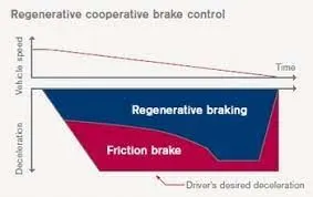
- In the Electric Driven Intelligent Braking System, the braking force is provided with the help of a ECU controlled motor and ball screw arrangement.
- This means that no direct load on the engine while applying brakes.
- This means that a motor operated the brake for providing the braking energy.
- A more controlled and uniform braking force is applied since its ECU controlled, this helps to recover braking losses when a regenerative braking system is used.

----------------------------------------------------------------------------------------------------------------------------------------------------------
Objective -
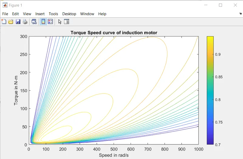
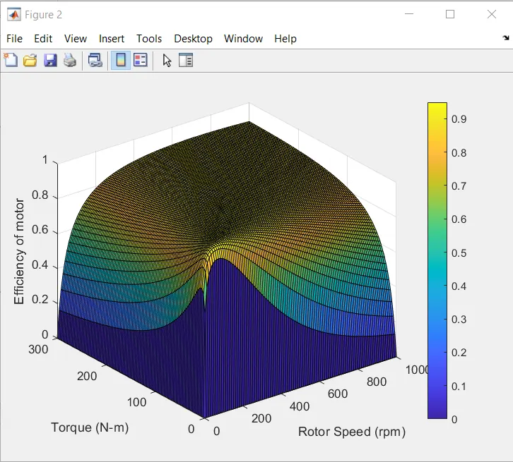
To make a MATLAB program which plots contour of given motor speed, torque and efficiency values.
MATLAB CODE -
clc

% RPM
w = linspace(0,1000);

% Torque N-m
T = linspace(0,300);

% Loss Coefficients
kc = 0.18;       % Copper Loss coefficient
ki = 0.0054;     % Iron Loss coefficient
kw = 0.000021;   % Windage Loss coefficient

% Meshgrid
[X,Y] = meshgrid(w,T);
Pcu = (Y.^2)*kc;   % Copper Loss
Pi = X.*ki;        % Iron Loss
Pw = (X.^3)*kw;    % Windage Loss
K = 20;
Pout = X.*Y;       % Output Power
Pin = Pcu+Pi+Pw+Pout+K;      % Input Power
Eff = Pout./Pin;
n = [0.70,0.72,0.75,0.77,0.79,0.80,0.81,0.82,0.83,0.84,0.85,0.86,0.87,0.88,0.89,0.90,0.91,0.92,0.93,0.94,0.95];

% Plotting the contour
box off
grid off
contour(X,Y,Eff,n);
xlabel('Speed in rad/s');
ylabel('Torque in N-m');
hold on
zlabel('Efficienccy');
title('Torque Speed curve of induction motor');
figure
surf(X,Y,Eff);
colorbar
xlabel('Rotor Speed (rpm)');
ylabel('Torque (N-m)');
zlabel('Efficiency of motor');
Result -