Week-11 Challenge: Braking
1.
here they asked me to calculate the energy required for braking.
so, now i had created a new driving cycle with the values of time in seconds and the velocity in mt/sec.
and after assigned those values i had calculated the braking energy in joules
and after i had coverted the calculated energy (joules) into energy(KWh) by using the formulae Ej/1000*3600
and then to be more specific i also calculated the cumulative braking energy(KWH)
from the obtained values i had plotted a graph between velocity and the cumulative braking energy
below i am attaching the image of those plots obtained from the drive cycle data
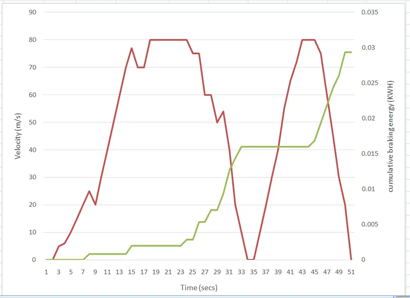
as we see from the above figure as there is a change in the velocity the braking energy required is changed
if the velocity value is decreased very high at that period the braking energy required is high
as per duty cycle of mine thye total braking energy used is 0.4495 KWH
2.
Electric motor can't develop braking torque at high speed similar to starting, because Braking torque is applied in the opposite direction of the rotation.
So, we can use mechanical brakes to develop a braking torque, we can also do it electrically
Regenerative braking is an energy recovery mechanism that slows down a moving vehicle or object by converting its kinetic energy into a form that can be either used immediately or stored until needed
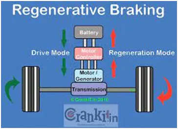
Regenerative braking harnesses the energy expended while slowing a vehicle to help recharge the batteries, tapping into the ability of an electric motor to turn into a generator.
This means that once the driver lets go off the accelerator pedal, regenerative braking activates instantaneously, but then there is a delay before the brake lights come on.
When you step on your petrol or diesel car’s brake pedal, hydraulic fluid pushes brake pads against brake discs on each wheel (or drums on older and cheaper models). The resulting friction works to slow the car down, generating heat and wearing away at the material on the pads and discs in the process.
Regenerative braking is a way of taking the wasted energy from the process of slowing down a car and using it to recharge the car’s batteries. On a normal car, braking simply wastes energy - but with regenerative braking, some of the energy is able to be reused.
Regenerative braking systems are common on many modern cars. On petrol and diesel models, it’s used to charge the battery that runs various ancillary systems in the car, meaning less work for the engine and less fuel burned. In these cars, the system is virtually imperceptible to the driver but in hybrid and pure electric cars regenerative braking takes a more active and obvious role. In these models, brake regeneration can help charge the larger batteries that directly drive the car.
How does regenerative braking work?
The electric motor in your hybrid or electric car runs in two directions - one to drive the wheels and move the car, and the other to recharge the battery. When you lift your foot off the accelerator pedal and onto the brake, the motor swaps directions and starts to put energy back into the battery.
In most cases, the electric motor/generator will provide sufficient braking power to slow the vehicle. Yet, when it's travelling at high or very low speeds, is stationary or the battery is fully charged, too hot or too cold, the electric motor cannot provide enough braking torque on its own and will need the support of a hydraulic braking system. To what extent will largely depend on the vehicle. For example, on earlier generation Toyota Prius’ (2001-2004), the hydraulic brakes are not used until the vehicle is below seven miles per hour, except for hard stops.
Electrical and mechanical brakes coordination
Generally Electric motor doesn’t have high torque capacity to handle all of the vehicle braking. Hence during the initial braking time, mechanical brakes are used in larger proportion than regenerative braking.
Once the braking torque value starts to decrease the regenerative braking is increased in proportion.
Basically, there are three different brake control strategies:
- series braking with optimal braking feel
- parallel braking
Series Brake -- Optimal Feel
The control objective is to minimize the stopping distance and optimize the driver's feel.
When the commanded deceleration (represented by the braking pedal position) is less than 0.2g, only the regenerative braking on the front wheels is applied, which emulates the engine retarding function in conventional vehicles.
When the commanded deceleration is greater than 0.2g, the braking forces on the front and rear wheels follow the
ideal braking forces
distribution curve I, as shown in Figure 1 by the thick solid line.
The braking force on the front wheels (driven axle) is divided into two parts: regenerative braking force and mechanically frictional braking force.
When the braking force demanded is less than the maximum braking force that the electric motor can produce, only electrically regenerative braking will apply.
When the commanded braking force is greater than the available regenerative braking force, the electric motor will operate to produce its maximum braking torque, and the remaining braking force is met by the mechanical brake system.
It should be noted that the maximum regenerative braking force produced by an electric motor is closely related to the electric motor's speed.
At low speed (lower than its base speed), the maximum torque is constant.
However, at high speed (higher than its base speed), the maximum torque decreases hyperbolically with its speed.
When the brake pedal is pressed the hydraulic fluid reaches the brake piston and created the braking pressure on the wheels and the same kinetic energy is been used by the Regenerative Braking for generating more power using the Bi-directional motor which operates as a generator while braking
3.
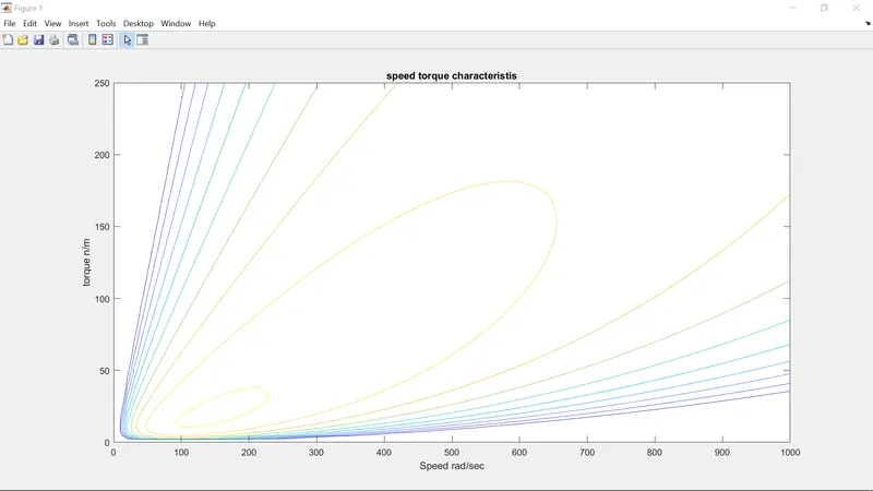
here they asked me to make a MATLAB program which plots contour of given motor speed, torque and efficiency values
so, i opend my MATLAB and creared a new script with the class video reference and here is the program is
% matlab program for plotting contour plot of motor speed and torque
clc
close all
clear all
% speed array
w = linspace(0,1000);
% torque array
t = linspace (0,250);
% loss coefficients
% copper losses
kc = 0.18;
% iron losses
ki = 0.006;
% windage losses
kw = 0.000015;
% meshgrid
[x,y] = meshgrid(w,t)
copper_losses = (y.^2)*kc
iron_losses = x*ki
windage_loss = (x.^3)*kw
cons = 20
o_p = x.*y
input_power = (copper_losses)+(iron_losses)+(windage_loss)+(o_p)+cons
eff = (o_p)./(input_power)
n = linspace (0.7,0.95,10)
box off
grid off
contour(x,y,eff,n)
title ('speed torque characteristis')
xlabel('Speed rad/sec')
ylabel('torque n/m')
and after running the program the obtained output are attached below in the form of image
Note : below i am attaching the .m file of the matlab for the 3rd Question reference and also attaching the excel sheet of the duty cycle for the 1st question reference. please consider it.
Thank you,
B. V. N. SANDEEP