Week-11 Challenge: Braking
1) AIM: For a defined driving cycle, calculate the energy required for braking.
driving cycle :
- is a series of data points representing the speed of a vehicle versus time.
- Driving cycles are produced by different countries and organizations to assess the performance of vehicles in various ways, as for instance fuel consumption, electric vehicle autonomy and polluting emissions.
- Fuel consumption and emission tests are performed on chassis dynamometers.Tailpipe emissions are collected and measured to indicate the performance of the vehicle.
- Another use for driving cycles is in vehicle simulations. More specifically, they are used in propulsion system simulations to predict performance of internal combustion engines, transmissions, electric drive systems, batteries, fuel cell systems, and similar components.
calculate the energy required for braking:
solution:
Braking energy is kind of converted kinetic energy so formula to calculatr braking energy is
=1/2*m*v^2
where
V is the (final velocity-initial velocity).
mass of the vehicle is=1150
we have deceleration points in our excel sheet data of drive cycle data.
calculate braking energy
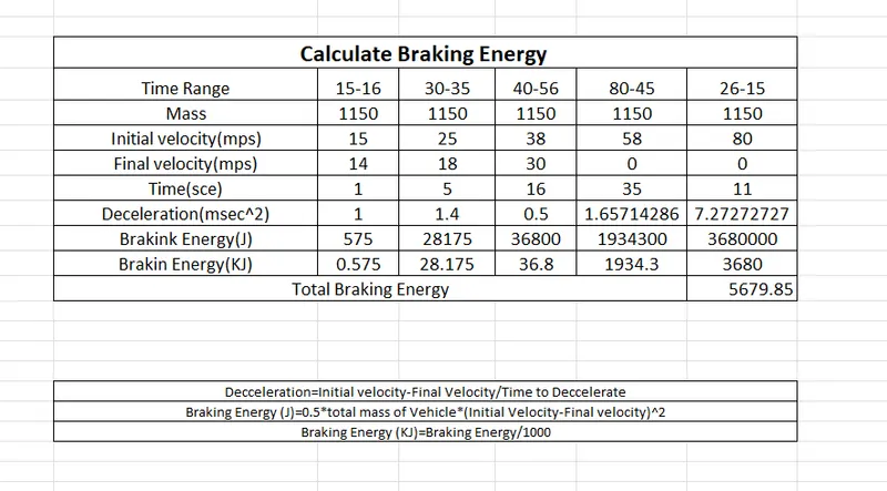
The Total Braking Energy is 5679.85 KJ
2) AIM: Why electric motor can’t develop braking torque at high speed similar to starting? How electric and mechanical brakes are coordinated?
solution:
- This situation does not occur at the beginning of an acceleration because most of the torque is used to increase the kinetical energy of the load (and motor).
But when the speed is already high and no extra load is applied it is not possible to increase the torque.
How electric and mechanical brakes are coordinated:
Electric Braking:
- is usually employed in applications to stop a unit driven by motors in an exact position or to have the speed of the driven unit suitably controlled during its deceleration.
- Electrical braking is used in applications where frequent, quick, accurate or emergency stops are required.
- Electrical Braking allows smooth stops without any inconvenience to passengers.
- When a loaded hoist is lowered, electric braking keeps the speed within safe limits. Otherwise, the machine or drive speed will reach dangerous values.
- Electrical Braking is more commonly used where active loads are applicable. In spite of electric braking, the braking force can also be obtained by using mechanical brakes.
Types of Electric Braking:
There are three types of electric braking
1) Plugging or Counter-Current Braking
2) Dynamic (or Rheostatic) Braking
3) Regenerative Braking
1) Plugging or Counter-Current Braking:
- This is the simplest type of braking. Plugging or counter-current braking occurs when the motor windings are connected for reverse direction of rotation at a time when the armature is still rotating in the forward direction either under the action of an external torque or due to inertia. Plugging involves reconnection of power supply to the motor so that it tends to drive in the opposite direction.
- It is obvious that, left to itself, the system will come to rest and then accelerate in the reverse direction.
- In case, it is required to bring the drive system to rest, it is necessary to include a special device to cut off the supply exactly at the instant when the motor stops.
2) Dynamic (or Rheostatic) Braking:
- In this method of braking the motor is disconnected from the supply and operated as a generator driven by the kinetic energy of the rotating parts of the motor and its driven machines.
- Thus the kinetic energy of rotation is converted into electrical energy, which is dissipated in the external resistance connected across the motor at the braking instant.
- By this method, energy required from the supply to brake the motor, has been eliminated as compared to the previous method (plugging) and this is marked advantage.
- This method of braking can be applied to brake the direct current motors, synchronous motors, and induction motors with a separate source of dc excitation during braking.
3) Regenerative Braking:
- In the previous two methods of electric braking namely plugging and rheostatic braking stored energy of the rotating parts of the motor and its driven machine is wasted whilst in plugging extra energy is drawn during the braking period and is wasted.
- In regenerative braking, mechanical energy is converted into electrical energy, part of which is returned to the supply and the rest of the energy is lost as heat in the windings and the bearings of the electrical machines.
- Regeneration does not, in general, involve any switching operation, unless it is required to change the speed at which it becomes effective.
- Most of the electrical machines pass smoothly from motoring to generating operation, when overdriven by load.
Mechanical Braking:
- he mechanical braking system powers the hand brake or emergency brake.
- It is the type of braking system in which the brake force applied on the brake pedal is carried to the final brake drum or disc rotor by the various mechanical linkages like cylindrical rods, fulcrums, springs etc. In order to stop the vehicle.
Types of Mechanical Braking:
1) DISC BRAKE
2) DRUM BRAKES
1) DISC BRAKE:
- The disc brake is a mechanism for slowing or stopping the rotation of a wheel from its motion.
- A disc brake is normally made of cast iron, but in some cases, it is also made of composites such as carbon-carbon or ceramic -matrix composites.
- This is linked to the wheel and/or the axle. To stop the wheel, friction material in the form of brake pads is forced against both sides of the disc.
- Friction caused, on the disc wheel will slow or stop.
2) DRUM BRAKES:
- A drum brake is a traditional break in which the friction is caused by a set of shoes or pads that press against a rotating drum-shaped part called a brake drum.
- The term "drum brake" usually means a brake in which shoes press on the inner surface of the drum.
- Where the drum is pinched between two shoes, similar to a standard disk brake , it is sometimes called a "pinch drum brake", although such brakes are relatively rare.
Comparison between Electrical and Mechanical Braking Systems:
- Electrical braking systems are used for functional braking (controlling the
speed; bringing the load to standstill). Mechanical braking systems are used
for emergency stopping or for parking. - Electrical braking is usually very smooth and comfortable. Mechanical braking
is usually rough and uncomfortable. - No wear results from electrical braking. Mechanical braking on the other hand
causes wear in the braking components and requires regular maintenance. - It is possible (but not always feasible) in electrical braking systems to return
the regenerated energy back to main supply. This is not possible in
mechanical braking systems and the energy is always lost as heat, noise and
wear. - The electrical braking system cannot be used as a safety device. Most
systems will require a mechanical braking system as a backup safety device.
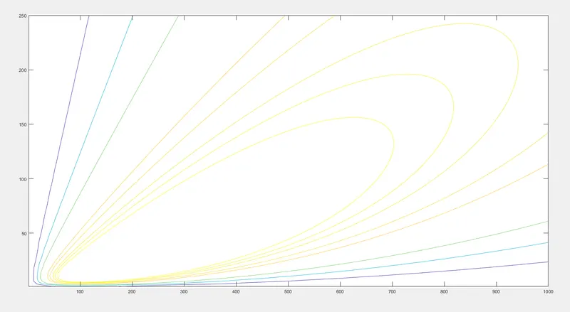
3) AIM: Make a MATLAB program which plots contour of given motor speed, torque and efficiency values. Attach the code as a .m file attach a screenshot of all the plots.
clear all
close all
clc
%motor efficiency
%a program for plotting efficiency contours for
%electric motor
%the x axis corresponds to motor speed (w)
%and the y axis to torque t
%first set up arrays for range
x=linspace(1,1000); %motor speed in rad/s
y=linspace(1,250); %motor torque in N-m
%motor loss constants
kc=0.2; %copper losses constant
ki=0.008; %iron losses constant
kw=0.00001; %windage losses constant
conL=20; %for constant motor losses
%now make mesh
[x,y]=meshgrid(x,y);
outputpower=(x.*y);%torque x speed=power
B=(y.^2)*kc; %copper losses
C=x*ki; %iron losses
D=(x.^3)*kw; %windage losses
inputpower=outputpower+B+C+D+conL;
Z=outputpower./inputpower;
%we now set the efficiencies for which a contour
%will be plotted
V=[0.70, 0.80, 0.85, 0.90, 0.91, 0.92, 0.925, 0.93];
box off
grid off
contour(x,y,Z,V);
x label('speed/rad.s^_^1'), y label('torque/N.m');
hold on
%now plot a contour of the power output
%the array output power has
%already been calculated we draw contours at
%3 and 5kw
V=[8000,10000];
contour(x,y,outputpower,V);
output plot: