Week-11 Challenge: Braking
1.For a defined driving cycle, calculate the energy required for braking
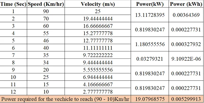
The above table represents the Duty cycle and Braking power required for the vechicle
The calculations are done by the following method
We know that Work done (Acceleration power) = 0.5 * m * V^2
m ----> Mass of the vehicle in kg
m = 800 kg
V -----> Velocity of the vechicle in m/sec
V = Vi - Vf
Vi ----> Initial velocity of the vehicle
Vf ----> Final velocity of the vehicle
For example
Lets consider the data from the table from 1 - 2 sec
Vi = 25 m/s
Vf = 19.44 m/s
Braking Power (kW) = (0.5 * m * V^2)/(1000 * T)
T ------> Time taken by the vehicle
T = Tf - Ti
Ti ----> Initial time of the vehicle
Tf ----> Final Time of the vehicle
For example
Lets consider the data from the table from 1 - 2 sec
Ti = 1 sec
Tf = 2 sec
T = 1 sec
Braking Power (kW) = (0.5 * 800 * (25-19.44)^2) / (1000 * (2 - 1))
Braking Power (kW) = 13.11 kW
Braking power required to attains its minimum speed (90km/hr to 10 km/hr) = 19.079 kW (or) 0.00529 kWh. This is the braking power in the time period of (1 - 12 sec).
2.Why electric motor can’t develop braking torque at high speed similar to starting? How electric and mechanical brakes are coordinated?
- Motoring Operation (Starting Torque)
- It is the first quadrant operation.
- Where the speed and torque is positive ,So the power is positive.
- In this quadrant the starting torque of the motor is high , This results in the low speed characteristic operation of the motor.
- Hence the motor operates in the constant torque region.
- Regenerative braking
- It is the second quadrant operation.
- Where the speed is positive and the torque is negative , So the power is negative.
- In this quadrant the toque is low and the speed is high.
- This operation obtained when the motor runs above the synchronous speed.
- Here the motor operates as generator.
Electric motor can’t develop braking torque at high speed similar to starting because of these following reasons
- In regenerative braking the torque is compromised because the motor operates in field weakining state which results in lower braking torque and higher acceleration .
- Due the higher acceleration we cannot obtain the required speed of the vechicle like in motoring opertion of the vechicle in the required time period
- For example
- If the vechicle reaches the speed of 0-60 km/hr in 3 sec in motoring operation.
- In regenerative braking the same vechicle cannot reaches the speed of 60-0 km/hr in 3 sec.
- For example
- The following factors affect the regenerative braking in EV
- Bidirectional power flow for 3 phase inverter (limit in reverse direction of power flow) .
- The battery should have better charging capacity (charging limit of the battery).
- More no of power converters are required.
- Regenerative braking is not applicable when the battery is fully charged.
- Regenerative braking is suitable in case where the vechicle operates at low speed.
Coordination of electric and mechanical brakes
To overcome drawbacks mentioned in electrical braking the combination of electric and mechanical brakes are used .
- When the Acceleration is high the mechanical brakes are applied until it reaches the low braking torque.
- When the motor reaches the low braking torque the electrical braking (regenrative braking ) is applied.
- They are classified into three categories,They are
- Series Braking
- Either regenerative or mechanical braking is applied one after another.
- Parallel Braking
- Both regenerative and mechanical braking is applied simultaneously at the same time.
- Series Braking
- Electric Driven Intelligent Brake System
- This system is introduced in Hybrid Nissian Fuga.
- This system is the combinational of Hydraulic , Regeneration , Mechanical Braking.
-
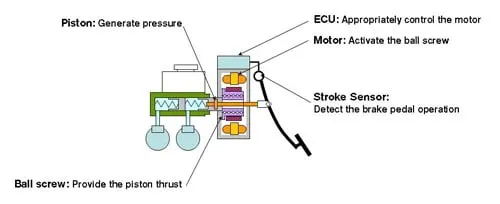
- In the Electric Driven Intelligent Braking System, the braking force is provided with the help of a ECU controlled motor and ball screw arrangement.
- This means that no direct load on the engine while applying brakes.
- This means that a motor operated the brake for providing the braking energy.
- A more controlled and uniform braking force is applied since its ECU controlled, this helps to recover braking losses when a regenerative braking system is used.
3.Make a MATLAB program which plots contour of given motor speed, torque and efficiency values. Attach the code as a .m file attach a screenshot of all the plots.
SCRIPT
clear all
close all
clc
x=linspace(1,1000);   %speed in rad/sec
y=linspace(1,250);    %Torque in Nm
Kc=0.2;               %Co efficient of Copper
Ki=0.008;             %Co efficient of Iron
Kw=0.00001;           %Co efficient of Windage
Km= 20;               %Co efficient of motor
[X,Y]=meshgrid(x,y);
Op=(X.*Y);            %Output Power of the motor
Cu=(Y.^2)*Kc;         %Copper loss calculation
Fe=X*Ki;              %Iron loss calculation
W=(X.^3)*Kw;          %Windage loss calculation
Ip=Op+Cu+Fe+W+Km;     %Input power of the motor
Eff=Op./Ip;           %Efficiency of the motor
V=[0.70,0.80,0.85,0.90,0.91,0.92,0.925,0.93]; % Efficiecy to plot contour
box off
grid off
contour(X,Y,Eff,V)    %plotting the plot as contour
xlabel('Speed(rad/sec)');
ylabel('Torque(Nm)');
title('Motor Speed-Torque Efficiency');
hold on
CALCULATION EXPLANATION
- This Calculation is applicable for Induction motor. The motor consists of various losses,They are
- Copper Loss(Cu)
- The general formulae for calculating copper loss is (I^2*R).
- R -----> Armature rresistance of the motor.
- I ------> Current flowing through the conductor of the armature.
- The general formulae for calculating copper loss is (I^2*R).
- For this calculation W.K.T current flowing throught the conductor is directlly proportional to torque(T).
- The resistance of the armature winding is given as copper coefficient (Kc).
- Copper loss = Kc * T^2
- Iron Loss(Fe)
- The iron loss is represented by magnetic losses .
- Iron loss is depend on the magnetic field which changes according to the speed (W(rad/sec)) of the motor.
- The iron loss is represented as iron coefficient (Ki).
- Iron loss = Ki * W
- Windage Loss(W)
- The windage loss is represented as mechanical (fictional) losses .
- Iron loss is depend on size and shape of the motor.
- The windage loss is represented as windage coefficient (Kw).
- Windage loss = Kw * W^3
- Constant Loss(Km)
- The motor has some constant losses which is fixed one which is represented as Km.
- Output Power(Op)
- The output power is calculated by the product of the Torque and Speed
- Output power = Torque(T) * Speed (W)
- The output power is calculated by the product of the Torque and Speed
- Total Loss
- The sum of the above mentioned losses is total losses.
- Total Losses = (Kc * T^2) + (Ki * W) + (Kw * W^3) + Km
- The sum of the above mentioned losses is total losses.
- Input Power(Ip)
- The input power is calculated by the sum of Output power and the all the losses
- Input power = Output power + Total losses
- The input power is calculated by the sum of Output power and the all the losses
Script Explaination
- This script can break into 3 parts.
- 1ST PART
- Here the Torque , Speed are given using linspace.
- The coefficient (Ki,Km,Kw,Kc,C) are mention as constant values.
- By using Meshgrid the speed and torque values are copied to X and Y matrices.
- 2ND PART
- Here the calculation work is done.
- The calculation are done by using the above mentioned formulae (Copper loss, Windage loss,Iron loss,Total loss).
- The efficiency is calculated by the ratio of Output power to the Input power.
- 3RD PART
- The output is obtained here as the contour plot by the help of contour function.
- contour (X,Y,Eff,V) specifies the X,Y,Eff are the coordinates for the value in V.
Result
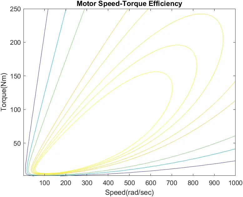
- The above plot shows the Motor Speed-Torque efficiency contour plot.
- The inner curves have the higher efficiency .
- As the curve goes outside the efficiency becomes reduces.
- The efficiency are calculated based on the losses.