Week-11 Challenge: Braking
OBJECTIVE:
- To calculate the braking energy for a defined driving cycle.
- To state why electric motor can’t develop braking torque at high speed similar to starting.
- To state how electric and mechanical brakes are coordinated.
- To make a MATLAB program which plots contour of given motor speed, torque and efficiency values. Attach the code as a .m file attach a screenshot of all the plots.
SOLUTION:
OBJECTIVE - 1:
TO CALCULATE BRAKING ENERGY FOR A DEFINED DRIVING CYCLE:
- Braking is the process of controlling the velocity of an object by inhibiting its motion. An object in motion possesses kinetic energy and to bring the object to a stop this kinetic energy must be removed. Removing the kinetic energy can be accomplished by dissipating the energy to the atmosphere through friction or by converting it into another form of energy. The most common type of braking is a mechanical brake which inhibits motion through friction brake pads. A mechanical brake applies a friction force to convert the kinetic energy of the vehicle into thermal energy which then dissipates into the atmosphere. Braking systems which don't use friction are referred to as Regenerative Braking Systems (RBSs). In RBSs, the kinetic energy is converted into other forms of useful energy, which can be stored for later use, increasing fuel efficiency.
- Kinetic Energy = `1/2*m*v^2`
- Braking Energy = `1/2*m*(v_i)^2 - 1/2*m*(v_f)^2`
- Braking Energy =`1/2*m*[(v_i)^2 - (v_f)^2]`
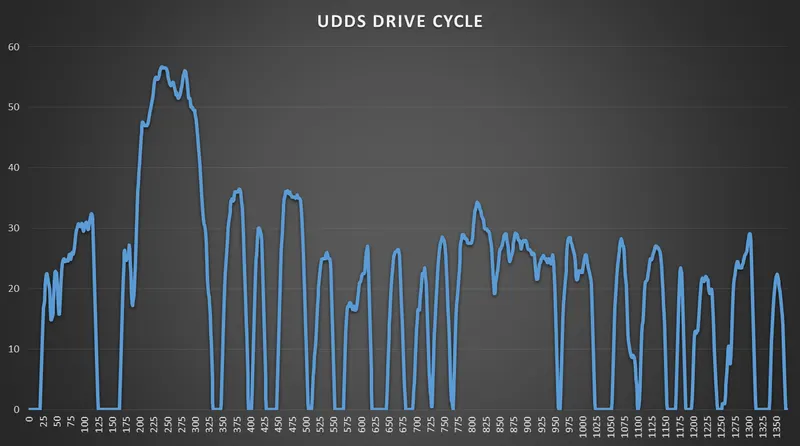
- To calculate the braking energy, we have considered the Urban Dynamometer Driving Schedule (UDDS) drive cycle.
- And the braking energy will be calculated using a MATLAB code.
URBAN DYNAMOMETER DRIVING SCHEDULE (UDDS) DRIVE CYCLE:
MATLAB CODE:
close all

clc

% DRIVE CYCLE DATA

% TIME
t = UDDSDriveCycledata(:,1);

% VELOCITY
v = UDDSDriveCycledata(:,2);

% MASS OF VEHICLE
m = 1000;

for (i=1:length(v)-1)

    if (v(i) > v(i+1))

        BE(i) = 1/2 * m * (v(i)^2 - v(i+1)^2);

    elseif (v(i) < v(i+1))

        BE(i) = 0;

    elseif (v(i)==0)

        BE(i) = 0;

    end

end


BE(i)=i+1; % To match the dimension of Time and Braking Energy
BE(i+1)=0; % Making the last entry as 0 as per the drive cycle

fprintf('The total braking energy is %d J \n', sum(BE))

figure(1)

subplot(2,1,1)
plot(t,v)
xlabel('Time (sec)')
ylabel('Speed (mph)')

subplot(2,1,2)
plot(t,BE)
xlabel('Time (sec)')
ylabel('Braking Energy (J)')
RESULTS:
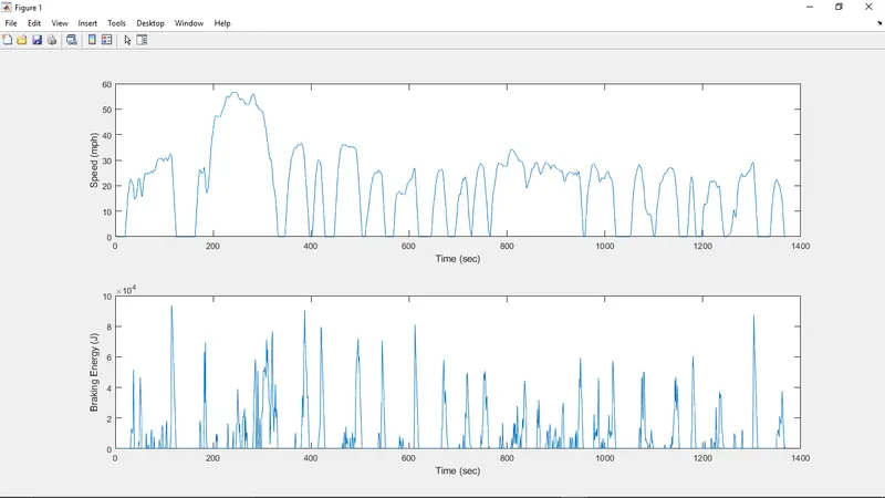
- From the above plot we can clearly observe that when the speed of the vehicle is reducing or dropping or the vehicle is decelerating only then braking energy is developed and when the speed of the vehicle increases or the vehicle accelerates there is no braking energy produced.
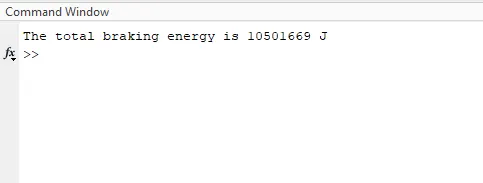
- The braking energy is 10501669 Joules.
OBJECTIVE - 2:
TO STATE WHY ELECTRIC MOTOR CAN'T DEVELOP BRAKING TORQUE AT HIGH SPEED SIMILAR TO STARTING:
- During starting of the vehicle, the vehicle is at low speed or no speed and to accelerate the vehicle from the rest condition a high amount of current is required and as we know current is directly proportional to Torque so, the Torque is very high during low speeds.
- But during braking the vehicle speed slows down from a higher speed to a lower speed so, due to high speed during braking condition the torque produced is low.
- And also, during braking the current that is produced when the speed of the motor is more than the no load speed Regenerative braking takes place and the voltage is fed back to the battery.
- But this voltage is not very high enough to completely recharge the battery.
- From this we can say that as the voltage and current values are very low during braking and as we know that Torque is directly proportional to the current so, the torque produced is also low.
- Therefore, the electric motor can't develop braking torque at high speed similar to starting.
OBJECTIVE - 3:
TO STATE HOW ELECTRIC AND MECHANICAL BRAKES ARE CORDINATED:
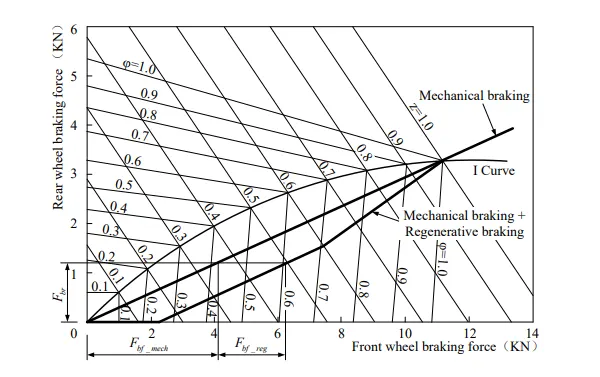
- The typical braking control strategy include the best brake feeling, the best energy recovery and parallel type braking control strategy, in which the former two that firstly consider the regenerative braking, and then to mechanical braking belong to serial braking control strategy. In contrast, the mechanical and regenerative braking are parallel and simultaneously produce braking force in the condition of the parallel braking.
- The mechanical braking of the parallel braking system can distribute the braking force of the front
and rear wheels in a fixed proportion and the regenerative braking supplement the braking force
insufficient on supplementary driving wheel, which forms the distribution curve of braking force
required by the driver. - The mechanical friction braking force applied on the front and rear axle is in direct proportion with
the hydraulic pressure in the brake master cylinder. Regenerative braking force is a function of the
hydraulic pressure in the main cylinder. Regenerative braking force is a function of the hydraulic
pressure in the brake master cylinder, which is also a function of the deceleration speed of vehicles
braking. - The basic strategy of the parallel braking control strategy:
- (1) When z is larger
When the braking strength of vehicles is larger (such as z =0.9), the braking energy is less due to the
shorter braking time, and the driving motor does not produce regenerative braking force to guarantee
the braking safety. - (2) When z is smaller
During the process of braking, regenerative braking is effective when z is less than 0.9. - (3) When z is very small
During the process of braking, when the z is less than a certain value, such as 0.1, it will just
require regenerative braking.
- (1) When z is larger
- The series-parallel regenerative braking control strategy of hybrid electric vehicle is designed
according to the basic idea of parallel braking control strategy as well the characteristics of regenerative
braking system of hybrid electric vehicle and the working characteristics of key components of
regenerative braking system such as driving motor and power battery. Set the z as the reference, and distribute the mechanical braking force and regenerative braking force to ensure the braking efficiency and recover as much braking energy as possible.
Electric Driven Intelligent Brake:
- In the Electric Driven Intelligent Braking System, the braking force is provided with the help of a ECU controlled motor and ball screw arrangement. This means that there is no direct load on the engine while applying brakes. This means that a motor operates the brake to provide the braking energy. A more controlled and uniform braking force is applied since its ECU controlled, this helps to recover braking losses when a regenerative braking system is used.
- The Electric Driven Intelligent Brake, another world’s first system, utilizes the vehicle’s electric motor to directly operate the brake cylinders. When the driver steps on the brake pedal, the necessary braking force is maintained while the hydraulic pressure of the friction brake is controlled to help maximize the energy regeneration of the hybrid motor. Because of its simple structure, in which the motor directly operates the brake cylinders, this new Electric Driven Intelligent Brake system has the potential to be applied to various future hybrid vehicles.
- This allows high environmental efficiency, while achieving an exhilarating driving experience with high-response linear acceleration levels that equal or exceed those of gasoline-powered cars.
OBJECTIVE - 4:
MATLAB PROGRAM TO PLOT THE CONTOUR OF GIVEN MOTOR SPEED, TORQUE AND EFFICIENCY:
- MATLAB CODE:
close all
clear all
clc

% x axis is Speed of motor in rad/sec
x = linspace(1,1000);

% y axis is Torque of motor in N-m
y = linspace(1,250);

k_c = 0.2;
k_i = 0.008;
k_w = 0.00001;
c_m = 20;

[x,y] = meshgrid(x,y);

% Power = T*Omega
p_out = x.*y;

% Copper Loss
c_l = k_c*(y.^2);

% Iron Loss
i_l = k_i*x;

% Windage Loss
w_l = k_w*(x.^3);

% Total Losses
T_l = c_l + i_l + w_l + c_m;

% Input Power
p_in = p_out + T_l;

% Efficiency
N = p_out ./ p_in;

v = [0.65,0.7,0.75,0.8,0.85,0.9,0.91,0.92,0.925,0.93];

figure(1)

contourf(x,y,N,v,'ShowText','on')
box off
grid off
c = colorbar;
c.Label.String = 'Efficiency'
xlabel('Speed (rad/sec)')
ylabel('Torque (N-m)')
colormap(jet)
- In this program first the motor speed and torque is defined and the value are stored in form of array in their respective variables.
- Then the value of different constants is defined in order to calculate the motor losses.
- A matrix of speed and torque value is formed.
- The Input power is calculated from the speed and torque. i.e
- P_in = Torque * speed (rad/sec)
- The motor losses are:
- Copper Loss: K_c * T^2
- Iron Loss: K_i * omega
- Windage Loss: K_w * omega^3
- Constant Loss: C
- All the losses are calculated based on their formulas and store in their respective variables.
- After that the total losses is calculated by adding all the individual losses.
- Then the Output power is calculated by subtracting the losses from the Input power.
- P_out = P_in + Total losses
- Then the efficiency of the motor is calculated by dividing the output power to the input power.
- Efficiency = P_out / P_in
- Then different values are defined in order to display them in the contour graph.
- At last, a contour graph is formed in order to observe the efficiency of the motor in the corresponding speed and torque region.
- RESULTS:
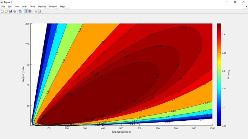
- From the above contour we can clearly observe the different efficiency regions.
- Also, from the contour we can clearly say that the smallest region at the center with the darkest red color is the maximum efficiency region.
- So, a motor operating in that region will give the maximum efficiency of about 93%.
CONCLUSION:
- From the above assignment we learnt to calculate the braking energy and checked the region where the braking energy will be produced.
- We also, calculated the braking energy of the Urban Dynamometer Drive Schedule (UDDS) drive cycle using MATLAB code.
- We also learnt why the electric motors can't develop braking torque at high speed similar to the starting condition.
- We also learnt about different brake control strategies used and how electric brakes and mechanical brakes work coordinately.
- We also learnt about different losses in a motor and saw the efficiency region of the motor.
- We also executed the above motor speed, torque and efficiency values using MATLAB code and made a contour to check the different efficiency regions and find out the maximum efficiency region.