Week-11 Challenge: Braking
Aim:-
To learn about braking in EV.
Objective:-
1) For a defined driving cycle, calculate the energy required for braking.
2) Why electric motor can’t develop braking torque at high speed similar to starting? How electric and mechanical brakes are coordinated?
3) Make a MATLAB program which plots contour of given motor speed, torque and efficiency values. Attach the code as a.m file attach a screenshot of all the plots.
Answer [1]:-
To calculate the energy required for braking, for a defined driving cycle.
- Whenever a force is applied to a vehicle’s brakes, there is work done due to the friction between the brakes and wheel. This reduces the vehicle’s kinetic energy, slowing it down and causing the temperature of the brakes to increase.
- The braking energy is the energy generated when the vehicle travelling at a certain speed comes down to low/zero speed. The braking power can be calculated when time taken for deceleration is also considered.
- To calculate the energy required for braking first, the driving cycle is defined in an excel sheet and plot is obtained.
- The plot for defined drive cycle is given below:-
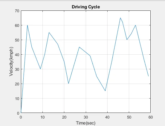
- From the plot we can see that, this driving cycle consists of five deceleration region i.e. five braking regions. The initial and final values of velocities along with time required are given as:-
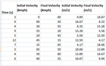
- The initial and final velocities are taken in kmph for driving cycle. So these values are converted in m/s for braking energy calculation.
- Kinetic energy is the force that keeps vehicle moving. This energy is provided by the engine in order to accelerate the vehicle from standstill to desired speed. Kinetic energy is dissipated as heat during braking.
- Thus kinetic energy of a vehicle during braking is given by:

Where;
m = mass of a vehicle in kg
Vi = initial velocity of a vehicle in m/s.
Vf = final velocity of a vehicle in m/s.
B.E = braking energy in Joules.
- For calculation we consider, the mass of vehicle = 1000kg.
- Now calculate deceleration & braking energy of the vehicle using excel calculator.
∴ Deceleration = change in velocity / time
= (Final velocity – Initial velocity) / time.
- The excel calculations are as given as:-
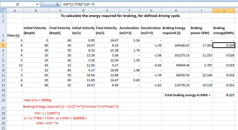
- Thus the total energy braking required is 0.127 KWh.
Answer [2]:-
A] Why electric motor can’t develop braking torque at high speed similar to starting?
Electric motor cannot develop braking torque at high speed similar to starting because braking torque is applied in the opposite direction of the rotation. Also, there are two major reasons for a motor developing high starting torque compared to braking:
a) Due to transients:-
At stating the motor draws a large current due to transients. As torque is proportional to a square of current, therefore torque value is also high at the starting of motor. When vehicle is running at high speed and we apply brakes, at this time current value is less therefore torque values are also less.
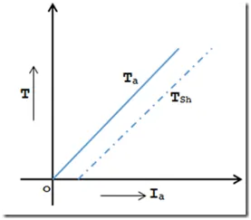
b) Torque speed characteristics:-
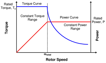
From torque-speed characteristics, when speed increases the torque should decrease to maintain power constant. At the time of starting, speed is very low therefore torque is high. When vehicle is running at high speed and we need to apply brake at that time we need high braking torque. But it is not possible to have high torque in constant power region. Thus at the time of braking, speed value is high therefore torque will be lower. Electric motors are designed for high starting torque. So motor will not produce high braking torque at high speed than during starting.
B] How electric and mechanical brakes are coordinated?
Electric and mechanical brakes are coordinated in mostly two ways:
- Series
- Parallel
1] Series brake control strategy:-
- Here we can apply mechanical brake & regenerative brake one after another. Also only one brake strategy is applied at a time i.e. either apply regenerative or apply mechanical brake.
- The regenerative braking system could restore kinetic energy & potential energy to a battery or any other forms of power during braking; it is a special system for EV & HEV. However, large current produced by generator during braking would affect battery performance and shorten battery life.
- A hybrid power system is an excellent energy storage system, in which ultra capacitor bank & battery packs are connected through a DC/DC power converter.
- The ultra-capacitor in this system can sore instantaneous large currents quickly, which is able to protect battery from large currents. This suggest that the ultra-capacitor is able to restore regenerative energy very quickly which will improve starting & acceleration performance, extend driving range and increase fuel economy.
- For low speeds of vehicle, regenerative braking is used but it may be limited acc. to SOC of battery. As speed of vehicle increases the rear wheel frictional brake will be applied, if braking requirement is not satisfied yet then front wheel frictional brake is also used
2] Parallel brake control strategy:-
- Here we can apply both mechanical brake & regenerative brake simultaneously.
- The regenerative braking system is own system of EV & HEV.
- The system restores the kinetic & potential energy used during start and accelerating into battery through electrical machine.
- When brake is applied according to the brake pedal travel; front wheel friction brake, rear wheel friction brakes & regenerative brakes are applied simultaneously. Higher the travel of brake pedal the higher the amount of braking will be done.
- Braking energy distributed in following manner: - Rear wheel friction brakes > Front wheel friction brake > Regenerative brake.
- The parallel brake strategy is not only safe enough but also can restore largest amount of brake energy.
Answer [3]:-
Make a MATLAB program which plots contour of given motor speed, torque and efficiency values. Attach the code as a.m file attach a screenshot of all the plots.
In order to find the efficiency of the motor, we need to consider various losses that occur in the motors operation. The various losses are:-
- Copper losses.
- Iron losses.
- Windage losses.
- Constant losses.
1] Copper losses:-
Cu losses = I2 * R
Where R = armature resistance
I = current
We know that torque is directly proportional to current then; the copper loss is considered as;
Cu loss = Kc * T2
Where Kc is to take care of resistance of brushes & also to take care of flux & its effect.
2] Iron losses:-
Iron losses are magnetic losses denoted by;
Iron loss = Ki * W
Where Ki is factor based on magnetic field effect.
3] Windage losses:-
These are mechanical or friction windage losses. This is based on size & shape of motor. The amount of windage losses that motor is going to experience is given as;
Windage loss = Kw * W3
4] Constant losses:-
These are motor constant losses, denoted by C.
- Thus total losses is given as:
Total losses = Cu losses + iron losses + windage losses + constant losses.
∴ Total losses = (Kc * T2) + (Ki * W) + (Kw * W3) + C
- For calculating efficiency we need to find input and output power.
Thus,
Output Power (Pout) = Torque * Speed = T * W -------------- (a)
Input Power (Pin) = Pout + losses = Pout + Cu loss + iron loss + windage loss + constant loss
Pin = Pout + (Kc * T2) + (Ki * W) + (Kw * W3) + C ------- (b)
∴ Efficiency = Pout / Pin ------------- (c)
Matlab program which plots contour of given speed, torque & efficiency:-
close all
clc
omega = linspace(0,1000); %speed of motor in rad/sec
torque = linspace(0,250); %torque produced by motor in N.m

%Allocate motor loss constants
kc = 0.2; %copper loss constant
ki = 0.007; %iron loss constant
kw = 0.0001; %windage loss constant
cl = 20; %constant motor loss

%Making 2D matrix
[T,W] = meshgrid(omega,torque);
%Calculate output power
Pout = (T.*W); % Power=torque*speed
%Calculate all losses
% Copper loss
b = (W.^2)*kc;

% Windage loss
c = (T.^3)*kw;

% Iron loss
d = T*ki;

%For input power
Pin = Pout + b + c + d + cl; %Pin=Pout+losses

%efficiency
E = Pout./Pin;

%set efficiencies for which contour to be plotted
V = [0.70,0.75,0.80,0.85,0.87,0.89,0.90,0.92,0.94,0.95,0.96,0.97];
box off
grid off
contour(T,W,E,V);
xlabel('Speed (rad/s)');
ylabel('Torque (Nm)');
title('Contour for motor speed, torque & efficiency')
Code explanation:-
- In above code, first speed & torque of motor are defined using linspace sommand.
- Then all loss constants values are entered in code.
- Then a 2D matrix is created for speed & torque using mesh grid command to help to create contour plot.
- Then all the losses, output power, input power & efficiency are calculated according to the formulas mentioned respectively.
- We have created another efficiency matrix so that we can set/ define certain levels for contour plot.
- Then we plotted contour using ‘contour’ command and title is also given to that contour plot.
- After completion of program in script file, we RUN the program to view the contour plot.
Plot:-
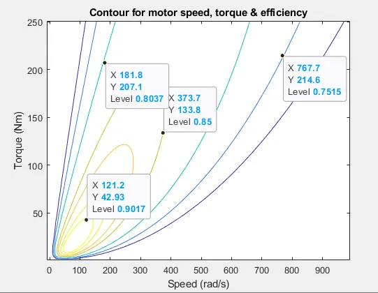
- Above plot shows contour plot for motor speed, torque & efficiency.
- The most efficient region in the contour is the innermost elliptical shape with efficiency over 90-95%.
- It is evident from contour that, the efficiency decreases as values are away from the innermost shape.
- As contour lines move away from center, efficiency falls even to 70%.
- From plot we observe that as speed increases, the efficiency of the motor reduces.
- It is optimal for motor to operate between the innermost ellipse and its adjacent one for maximum efficiency and performance.
Conclusion:-
1) The total energy braking required is 0.127 KWh.
2) Understood the reasons for a motor developing high starting torque compared to braking & two strategies for electric and mechanical brakes coordination.
3) From matlab program written to plot contour, we learnt that as we move away from center, the efficiency falls down.