Week - 4
Answer [1]:
Aim:-
To build a model to implement control logic of a “washing machine” using State flow.
Objective:-
Implement control logic of a “washing machine” using State flow as per given sequence:
- If the power supply is available, the system gets activated
- If the Water supply is not available, stop the process & indicate through LED
- Soaking time should be 200s followed by Washing time of 100s.
- Then rinsing happens for next 20s & dryer runs for 50s
- After all the processes have completed turn on the finished LED
Simulink Model:-
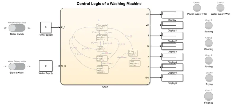
Fig 1:- Simulink model representing control logic of a “washing machine” using State flow.
State flow Chart:-
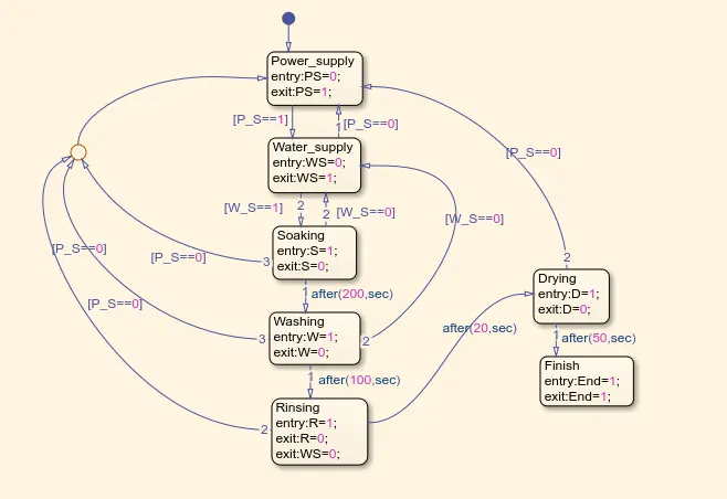
Fig 2:- State flow chart of washing machine logic.
Simulink Model & State flow chart Description:-
In order to implement a control logic using State flow as per given sequence, we have first build a logic to perform operation using "Chart Block". Double click on "Chart block" to build state flow control logic (as shown in fig 2). Now drag and drop the state icon from object palette in order to add new states to the chart; where this each chart is given its name based on the sequence of operation to be performed. The first state has always a "Default Transition" with it, to take the input for logic. So know take the first "state block" & name it as "Power_supply". This "Power_supply" state will check the whether the power supply is ON/OFF. Here we have defined a variable 'PS' for an output & 'P_S' for an input. The output of first state will go further only when power supply is ON. So when power supply is '1' (i.e. P_S=1), then the "Power_supply" block will give output as 'PS=1' indicating system gets activated & then only the supply is given to further state. But if power supply is '0' (i.e. P_S=0), then supply will not go further and further process will not take place. Here output will be 'PS=0'. Next we have "Water_supply" state, where water is supplied to a machine or not is checked. Here also we have defined a variable 'WS' for an output & 'W_S' for an input of a water supply. Here also when 'W_S=1', then only signal is passed further & if 'W_S=0', then further process is stopped. If "P_S=1" & "W_S=0"; indicates we don't have water supply then we won't be able to run the further process. And If "P_S=1" & "W_S=1"; then only signal/supply is passed further. So point to be remembered up till know is; as power supply is ON and water supply will also get ON, then only the operating states of washing machine starts.
Now further state is "Soaking state", where clothes are dipped in detergent water to remove dirt from the clothes. We want soaking time to be for '200sec'. So as soon as we get the water supply, machine starts the 'soaking operation' for 200sec. This delay of '200sec' is provided using 'after' logic. Here defined variable 'S=1' means that soaking process is going on for 200sec & when 'S=0' this means that soaking process is completed after 200sec. After 200sec, soaking operation will get stop and washing operation will start. For washing operation again new state named "Washing" is taken. Similar to soaking, washing operation is also provided with delay. Washing operation takes place for '100sec'. Here the defined variable 'W=1' means washing process is going on for 100sec & when 'W=0' means the washing process is completed. Now after 100sec, washing process is stopped and rinsing process starts where the soapy water must be spun from the clothing and wash tub. So next is "Rinsing" state. Here also when 'R=1' rinsing process is going on for 20sec & when 'R=0' process is stopped after 20sec. After 20sec, rinsing operation stops and drying operation starts. But before starting drying operation, water supply should be made OFF. So when rinsing process get completed after 20sec, at that time only water supply is made OFF by writing syntax as (exit:WS=0;) in 'Rinsing state'. As water supply is made OFF, now after 20sec of rinsing, drying process starts. Thus next is "Drying" state. Similar conditions are given here as in previous states. Drying process is ON (D=1) for 50sec. After 50sec the complete work of cleaning clothes is done/finished. Thus final state is "Finish" state. This state indicates that the whole process is completed and washing machine's power supply needs to be made OFF manually.
In fig 2, we have provided return path as [P_S==0] for almost each and every states where power supply is available & [W_S==0] for the states where water supply is available. This [P_S==0] is given because if there is any type of power failure during process, then washing machine should stop the process. For example: If during "Washing state" the supply is went OFF suddenly due to power failure, then due to return path [P_S==0], the "Power_supply" will go OFF. Similarly as we required water supply for soaking, washing & rinsing states only & during these state's if the water supply is made OFF may be due to lack of water in storage or due to any reason then the on going process should be stopped so we have provided [W_S==0] in return path for these three states. Now the control logic required for a “washing machine” using State flow is build. Now further step is to build a model.
Figure 1 represents Simulink model for control logic of a “washing machine” using State flow. Here the control logic build (shown in fig 2) is represented by "Chart block". This chart block has two inputs: 'P_S' & 'W_S' for power supply & water supply respectively. Also chart block has 7 outputs. These outputs are represented by a variables, they are: 'PS', 'WS', 'S', 'W', 'R', 'D', 'End'. All these outputs are connected to "Display block". For these 7 outputs, we have connected 7 different "Lamp block" respectively. These display blocks & lamps represent which state or process is going ON & which are not going ON. For input we have connected two "Constant blocks" to chart block. One constant block for power supply (P_S) & one for water supply (W_S). To provide ON & OFF logic to inputs, we have connected two "Slider Switch blocks" with two constant blocks respectively. This "Slider switch block represents ON (1) & OFF (0) state of a supply. If slider switch is ON, the constant block shows value as '1', this means that the input is ON & we are providing respective supply to the system. But when slider switch is OFF, the constant block shows value as '0', this means that the input is OFF & we are not providing respective supply to the system. The above logic of ON/OFF is applicable to both power supply & water supply. In this way the model is being created for control logic of a washing machine using state flow.
Symbols Pane:-
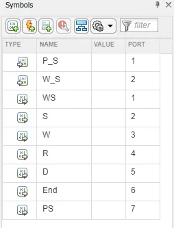
Fig 3:- Symbols pane window.
The above figure (fig 3) represents the window of symbol pane. Here all variables in state flow are defined & assigned as a input or output according to our requirement. In this case, there are two supplies, so power supply (P_S) & water supply (W_S) are assigned as input data. While rest of the variables that represent different operation stages of a washing machine are assigned as output data.
Simulation Results:-
- Condition I: No power supply & No water supply:-
Fig 4:- Simulink result when power & water supply are OFF.
The above figure shows that power & water supply is OFF. Here input given is '0' for both constant blocks as slider switch is at OFF position, so no process will take place. In fact the whole system is not even activated. So all the lamps in the output are in "Red colour", this tells that there is no power supply, water supply & also no any state is in process.
- Condition II: Power supply ON but water supply OFF:-
Fig 5:- Simulink result when power supply is ON & water supply is OFF.
The above figure shows that power supply is ON & water supply is OFF. Here constant block of power supply shows '1' as slider switch is at ON position; this represents the ON state of power supply. And the constant block of water supply shows '0' as slider switch is at OFF position; this represents that no water supply is provided. So the lamp that represents "Power supply (PS) is "Green colour" & rest lamps are in "Red colour". As power supply is available, the system gets activated but for operating all the stages/cycle of machine, we require the water supply.
- Condition III: Power supply ON & water supply ON:-
Fig 6:- Simulink result when power supply is ON, water supply is ON & soaking state ON.
The above figure shows that power supply is ON & water supply is ON. Here constant block of power supply shows '1' as slider switch is at ON position, this represents the power supply is provided. And the constant block of water supply shows '1' as slider switch is at ON position, this represents that water supply is provided. So the lamp that represents power supply (PS) & water supply (WS) are in "Green colour". Here know all the process starts to happen one after the other in a sequence provided.
Soaking State:
From figure 6 we can say that as power & water supply is provided to a washing machine, the soaking process is activated for 200sec. So the lamp that represents soaking state is in "Green colour" for 200sec, along with the power supply (PS) & water supply (WS) lamp. While rest other lamps are in "Red colour". Also display block shows '1' for power supply, water supply & soaking. While '0' for rest other display blocks.
Washing State:
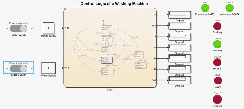
Fig 7:- Simulink result when washing state ON.
From figure 7 we can say that the soaking process that was started before is now stopped after 200sec. As soaking process is stopped, washing process is got activated for next 100sec. So the lamp that represents washing state is in "Green colour" for 100sec, along with the power supply (PS) & water supply (WS) lamp. While rest other lamps are in "Red colour". Power & water supply lamps are in green colour because if there is no water & power supply, washing process would have stopped. Also display block shows '1' for power supply, water supply & washing. While '0' for rest other display blocks. Display block for soaking shows '0' & lamp shows "Red colour" because the soaking process has got completed after 200sec.
Rinsing State:
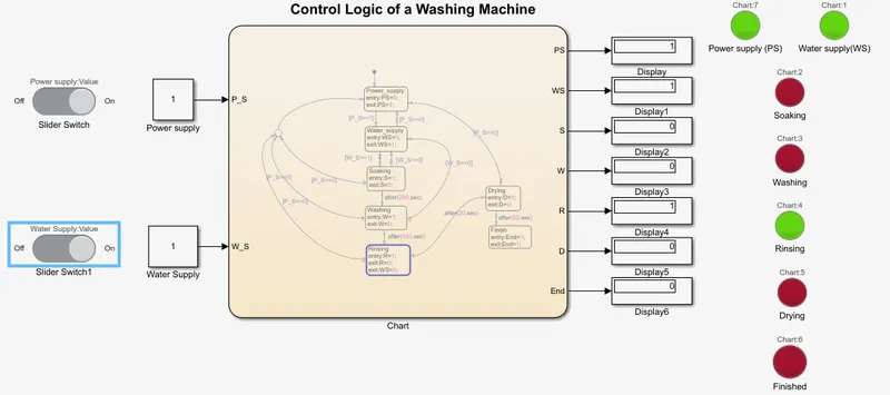
Fig 8:- Simulink result when rinsing state ON.
From figure 8 we can say that the washing process that was started before for 100sec is now stopped after 100sec. As washing process is stopped, rinsing process is got activated for next 20sec. So the lamp that represents rinsing state is in "Green colour" for 20sec, along with the power supply (PS) & water supply (WS) lamp. While rest other lamps are in "Red colour". Power & water supply lamps are in green colour because if there is no water & power supply, rinsing process would have stopped. Also display block shows '1' for power supply, water supply & rinsing. While '0' for rest other display blocks. Display block for soaking & washing shows '0' & lamps shows "Red colour" because these processes have got completed after 200sec & 100sec respectively.
Drying State:
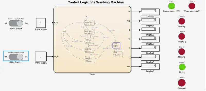
Fig 9:- Simulink result when drying state ON.
From figure 9 we can say that the rinsing process that was started before for 20sec is now stopped after 20sec. As rinsing process is stopped, drying process is got activated for next 50sec. So the lamp that represents drying state is in "Green colour" for 50sec, along with the power supply (PS) but here water supply (WS) lamp is in "Red colour". Water supply lamp is in red colour because we don't need water supply for drying process, so we have stopped the water supply after rinsing process have been completed. Also rest other lamps are in "Red colour". Power supply lamp is in green colour because if there is no power supply, drying process would have stopped. Also display block shows '1' for power supply & drying. While '0' for rest other display blocks. Display block for soaking, washing & rinsing shows '0' & lamps shows "Red colour" because these processes have got completed after 200sec, 100sec & 20sec respectively.
Finish State:
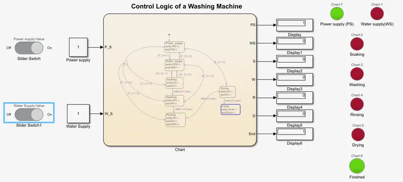
Fig 10:- Simulink result when washing cycle is completed.
From figure 10 we can say that the drying process that was started before for 50sec is now stopped after 50sec. As drying process is stopped, the whole cycle of washing clothes has got completed. So the lamp that represents finish state is in "Green colour", along with the power supply (PS). While rest other lamps are in "Red colour". Also display block shows '1' for power supply & finish state. Power supply lamp is in green colour & display shows '1' because as process of cleaning clothes is completed we need to manually OFF the power supply. Rest all state lamps are in red colour & displays shows '0' because all those processes have been completed successfully . Here we have build model that shows all processes are done one after the other so at last only Finish state is green coloured.
- Condition IV: Water supply has been stopped in between process:-
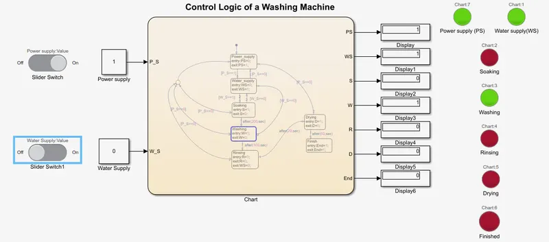
Fig 11:- Simulink result when Water supply has been stopped in between process.
Fig 12:- Simulink result when Water supply has been restored.
The figure 11 tells us that if suppose the water supply has been stopped due to some reason, then the system will start all over again. We can see here (fig 11) the washing state is going ON (washing lamp is green and display also shows '1') & water supply is made OFF (constant block of water supply shows 0). Due to this condition, the process will stop right there and there. As we have provided the return path for washing state it will again go back to the third state (as shown in fig 5/12) due to stopped water supply. And when water supply will come back again (i.e. Water supply=1) the whole process/cycle from soaking will start all over again (as shown in fig 12).
Conclusion:-
Hence the washing machine control logic has been successfully implemented & executed using state flow. Also all objectives have been achieved. Similarly we can use this concept to create other state flow systems.
Answer [2]:2]:
Aim:-
Create a Simulink chart for the “Gear shift” logic & vary speed & obtain the gear number in display.
Objective:-
Make a Simulink chart for the “Gear shift” logic as per below conditions:
|
Speed Range (kmph) |
Gear |
|
0 to 15 |
1 |
|
16 to 25 |
2 |
|
26 to 40 |
3 |
|
41 to 60 |
4 |
|
61 to 80 |
5 |
|
Above 80 |
Over speed |
Give speed input while the simulation is running & display the gear number.
Simulink Model:-
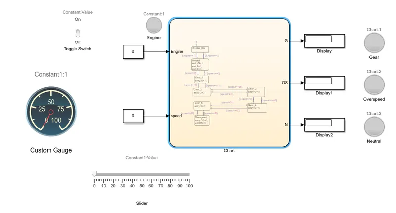
Fig 13:- Simulink model for the “Gear shift” logic.
State flow Chart:-
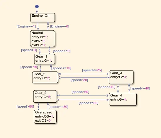
Fig 14:- State flow chart of Gear shift logic.
Simulink Model & State flow chart Description:-
Figure 14 is the state flow chart of gear shift logic. We have provided with the information that certain speed range in kmph is for certain gear. So to build this gear shift control logic we will first create logic in chart. Take "Chart block", in that drag and drop the state icon from object palette in order to add new states to the chart; where this each chart is given its name based on the sequence of operation to be performed. The first state has always a "Default Transition" with it, to get the input for logic. So know take the first "state block" & name it as "Engine_ON". This state provides the input to the system & tells us engine is ON/OFF. When input of engine is "Engine==1", engine is started and the signal is passed further & system is activated. If input of engine is "Engine==0", then the vehicle is not yet started & hence system is not activated. When ever engine input is made ON, the vehicle is at 'Neutral' position. So next state represents the "Neutral state". Here when "Engine==1" & speed=0; then "Neutral=1". Thus as we have not provided any speed at neutral position, so here vehicle is not on any gear. Hence we have written "(exit:G=0;)" during neutral state. Gear is shifted based on change in speed. So based on given data we have created different states for gear system. When speed>0 & speed<=15 the vehicle should be at gear 1. So next state is "Gear_1". Now when system is between 0 to 15 will signify gear number as '1'. After this when speed is increased let's say between 16 to 25 (i.e. speed>15 & speed<=25), then the vehicle should be at gear 2. So next is "Gear_2" state that will represent gear number as '2'. Now for speed range of 26 to 40, gear should be at 3. Thus next state is "Gear_3", that will represent gear number as '3' for speed>25 & speed<=40. Similarly for speed range of 41 to 60 (i.e. speed>40 & speed<=60), new state named "Gear_4" is assigned & for speed range of 61 to 80 (i.e. speed>60 & speed<=80), new state named "Gear_5" is assigned. Lastly for speed above 80, "Over speed state" is created. Here we are providing varying input as speed & gear number is assigned for the particular speed range. If speed of vehicle is greater than the earlier gear’s speed range, then the gear is changed. For example: if vehicle is at speed 20, means at gear 2 & know speed is changed from 20 to let’s say 30; then now the vehicle is at gear 3. Similarly if speed of vehicle is less than the earlier gear’s speed range, then the gear is changed. For example: if vehicle is at speed 30, means at gear 3 & know speed is changed from 30 to let’s say 20; then now the vehicle is at gear 2. This is possible because we have provided return path for each and every state. Also we have defined some variables that represent inputs & outputs of the system. We have defined/assigned the variables "Engine" & "speed" for the input of logic & variables "N" to represent neutral state in output, "G" to represent gear number in output and "OS" to represent over speed state in output. Thus in this way we have created a control logic for gear shift. Now further step is to build a model.
Figure 13 represents simulink model for the gear shift logic. As we have created the control logic in "Chart block"; know we need to connect input & output to the model. For input side we have connected one "Constant block" that represents Engine is ON/OFF & another "Constant block" that represents the varying speed input. These two constant blocks are connected to input of a chart block. Constant block that represents engine is linked with the "Toggle switch", that shows ON (1) & OFF (0) state of a input. If Toggle switch is ON, the constant block shows value as '1', this means that the engine is ON & we are providing respective signal to the system. But when toggle switch is OFF, the constant block shows value as '0', this means that the engine is OFF & we are not providing respective signal to the system. Similarly constant block that represents speed is linked/connected with "Slider" & "Custom gauge". The input value of speed given to system is varied using "Slider". We have set minimum & maximum value of slider as 0 & 100 respectively. So that we can vary the speed input from 0 to 100 & obtain the varying gear numbers in display for particular speeds. "Custom gauge" is connected to constant block so that the varying speed from slider will be reflected here. For the output side of chart we have connected three different "Display blocks". These display blocks are for neutral state, over speed state & to show gear number. Also the three "lamps" are connected to each of these display blocks that represents the ON/OFF state of neutral state, over speed state & to indicate 5 different colours which are assigned for 5 different gears. Also one lamp is connected to a input i.e. constant block of engine. This lamp indicates ON/OFF state of engine. In this way the model is being created for gear shift control logic. Single lamp is assigned for gear (G) output, to indicate 5 different colours at different state. The colour of lamp assigned for different states are shown as:
Fig 15:- States & colour of lamp assigned for different gears.
Symbols Pane:-
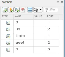
Fig 16:- Symbols pane window.
The above figure (fig 16) represents the window of symbol pane. Here all variables in state flow are defined & assigned as a input or output according to our requirement. The variables "Engine" & "speed" are assigned as an input data of engine and speed respectively; whereas "G", "OS" & "N" are assigned as an output data of gear, over speed & neutral state respectively.
Simulation Results:-
- Condition I: Engine OFF:-
Fig 17:- Simulink result when Engine is OFF.
The above figure (fig 17) shows that engine is at OFF state. Toggle switch is at OFF position, constant block of engine shows '0' value & also speed is '0' (i.e. speed is not provided). Hence no process is taking place as system is not activated & there is no any type of output at the end.
- Condition II: Engine ON:-
Neutral State:
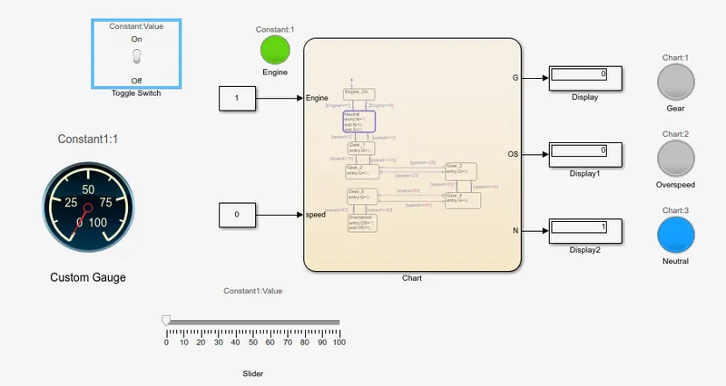
Fig 18:- Simulink result when Engine is ON, neutral state is ON at speed=0 kmph.
The above figure (fig 18) shows that engine is at ON state. Because toggle switch is at ON position, constant block of engine shows '1' value but speed is kept '0' (i.e. speed is not provided). As we have just made engine ON, the vehicle is at Neutral state. Here speed is kept '0', also display for gear shows '0' value. As engine is made ON & neutral state is also ON, due to this "Green colour" lamp of engine & "Blue colour" lamp of Neutral is ON.
Gear 1 State:
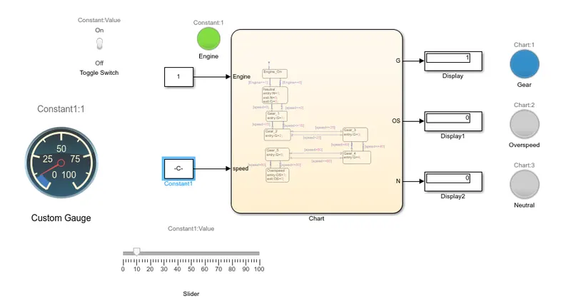
Fig 19:- Simulink result for speed between 0-15 kmph.
The above figure (fig 19) shows the result when speed is increased above 0. When speed range is 0 to 15 kmph (i.e. speed>0 & speed<=15), vehicle should be at gear 1. Here we have kept speed=10kmph. Thus output in display block of gear (G) shows '1', thus lamp indicates "Blue colour" which is assigned in the lamp block (see fig 15) for gear 1. Also engine lamp is ON for whole process. Custom gauge also indicates the speed as 10kmph.
Gear 2 State:
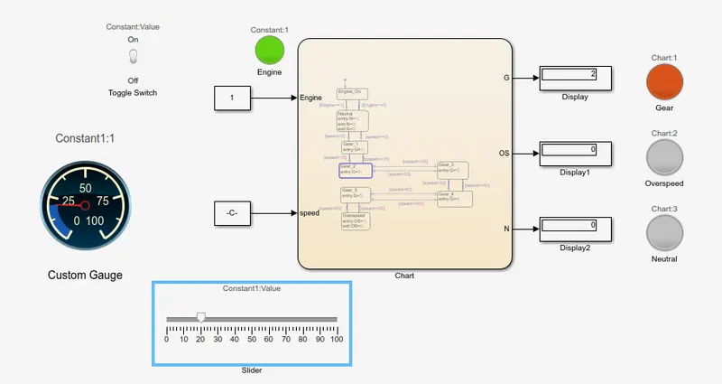
Fig 20:- Simulink result for speed between 16-25 kmph.
The above figure (fig 20) shows the result when speed is increased above 15. When speed range is 16 to 25 kmph (i.e. speed>15 & speed<=25), vehicle should be at gear 2. Here we have kept speed=20 kmph from slider. Thus output in display block of gear (G) shows '2', thus lamp indicates "Dark orange colour" which is assigned in the lamp block (see fig 15) for gear 2. Custom gauge also indicates the speed as 20kmph.
Gear 3 State:
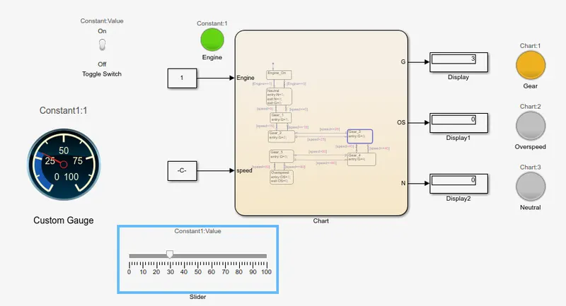
Fig 21:- Simulink result for speed between 26-40 kmph.
The above figure (fig 21) shows the result when speed is increased above 25. When speed range is 26 to 40 kmph (i.e. speed>25 & speed<=40), vehicle should be at gear 3. Here we have kept speed=30kmph from slider. Thus output in display block of gear (G) shows '3', thus lamp indicates "Dark yellow colour" which is assigned in the lamp block (see fig 15) for gear 3. Custom gauge also indicates the speed as 30kmph.
Gear 4 State:
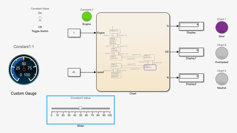
Fig 22:- Simulink result for speed between 41-60 kmph.
The above figure (fig 22) shows the result when speed is increased above 40. When speed range is 41 to 60 kmph (i.e. speed>40 & speed<=60), vehicle should be at gear 4. Here we have kept speed=50kmph from slider. Thus output in display block of gear (G) shows '4', thus lamp indicates "Violet colour" which is assigned in the lamp block (see fig 15) for gear 4. Custom gauge also indicates the speed as 50kmph.
Gear 5 State:
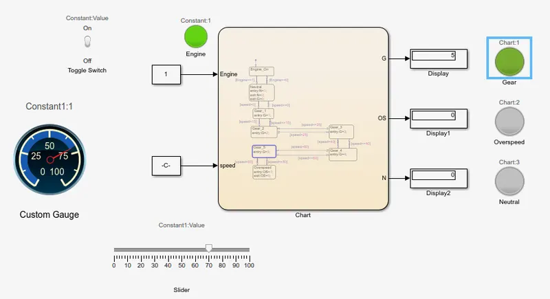
Fig 23:- Simulink result for speed between 61-80 kmph.
The above figure (fig 23) shows the result when speed is increased above 60. When speed range is 61 to 80 kmph (i.e. speed>60 & speed<=80), vehicle should be at gear 5. Here we have kept speed=70kmph from slider. Thus output in display block of gear (G) shows '5', thus lamp indicates "Green colour" which is assigned in the lamp block (see fig 15) for gear 5. Custom gauge also indicates the speed as 70kmph.
Over speed State:
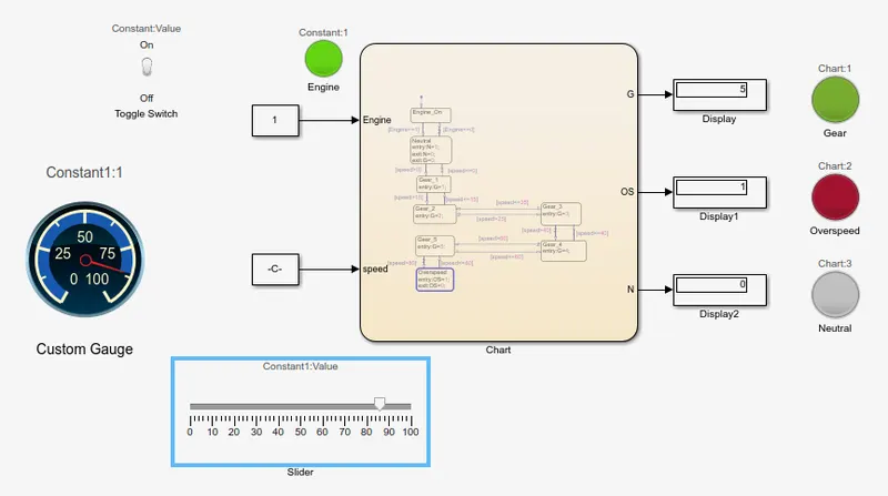
Fig 24:- Simulink result for speed above 80 kmph.
The above figure (fig 24) shows the result when speed is increased above 80. When speed range is 81 kmph to (inf) but here we have given max speed as 100 kmph (i.e. speed>80), vehicle should be at gear 5 & indicate over speed state. Here we have kept speed=85kmph from slider. Custom gauge also indicates the speed as 85 kmph. Thus output in display block of gear (G) shows '5', thus lamp for gear indicates "Green colour" which is assigned in the lamp block (see fig 15) for gear 5. Also as speed is above 80, display block of over speed (OS) shows '1', thus lamp for over speed indicates "Red colour" which is assigned in the lamp block. This indicates that over speed state is reached & we need to control the speed.
Conclusion:-
All the objectives have been successfully achieved. We have created simulink model for the Gear shift logic with the display of gear number & varying speed input using state flow.