Week-11 Challenge: Braking
Week 11 Challenge : Braking
Q1. For a defined driving cycle, calculate the energy required for braking.
Soln:
To calculated the braking energy, a typical drive cycle is considered as follows-
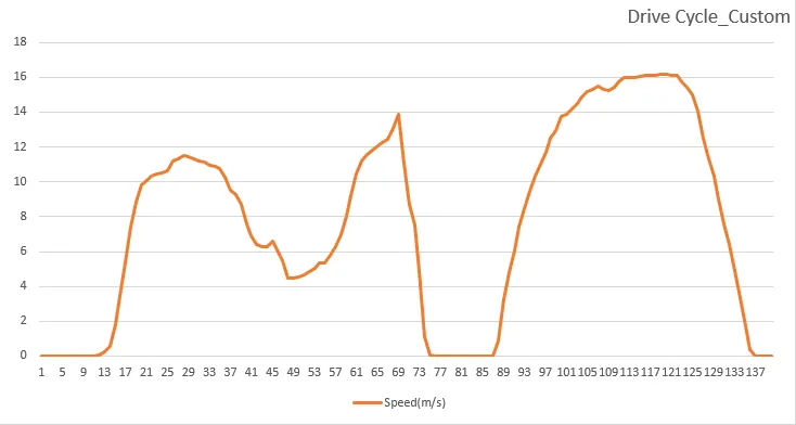
The drive cycle is 140 secs long , with top speed attained as 16.282848 m/s or 36.2 mph . In the cycle, brake is applied total of 5 times.
The formula for calculating the brake energy is given by –
Brake energy= 0.5*m*(vi-vf)^2
Where, m= total mass of the vehicle in kg
vi= initial speed of the vehicle in m/s
vf= final speed of the vehicle in m/s
Now, considering the total mass of the vehicle to be 1000 kg, the braking energy is calculated for all the 5 points of braking using excel calculator.
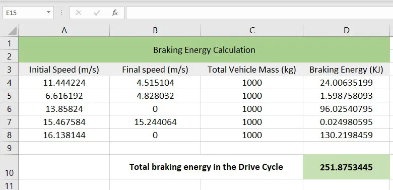
So, in the entire drive cycle, on 5 braking points the total braking energy required is 251.875 KJ. The braking power can be calculated
by just multiplying the time for braking with energy.
The excel file link- https://docs.google.com/spreadsheets/d/1JDbkJ6eTVNFtxxH31qWULw7sYDSkM_e6/edit?usp=sharing&ouid=117517265670986442247&rtpof=true&sd=true
Q2.Why electric motor can’t develop braking torque at high speed similar to starting? How electric and mechanical brakes are coordinated?
Soln:
The working of any electric motor can be explained from its speed torque characteristics. If we consider a typical dc motor Speed-torque characteristics, we can observe that at the starting of the motor , torque is high and speed is low. As the motor accelerates and crosses the threshold speed, the torque decreases but the power is kept at constant level by the increasing speed. This area is called the constant power region. The area where the torque is high is called the constant torque region.
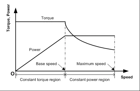
It is clear from the curve that at high speeds the motor works in constant power region where torque is less. So, motor cannot produce much braking torque in this region. That’s why a electric motor running at high speeds requires assist in braking as it cannot develop the required braking torque.
Electric and Mechanical Braking co-ordination:
In most EV and HEV, the common electrical braking method used is regenerative braking. This method allows the motor to work as generator when the brakes are applied. The braking torque produced is applied to the rotor shaft which stops the vehicle. The kinetic energy is transferred back to the battery in this method. But this method has some limitations. The regeneration of energy is limited by the battery charging rate and high SOC. And also when the vehicle is running at high speed, braking torque required is high ; which the regenerative braking alone cannot account for [as seen from torque-speed characteristics].As a result mechanical assist is required.
The cooperation of Mechanical Braking and Electric braking is very inportant in EV design for effective braking control strategy and is known as torque blending.
Basically, there are three different brake control strategies: Series braking with optimal braking feel; Series braking with optimal energy recovery; and Parallel braking.
- Series braking with optimal braking feel: In this control strategy both regenerative and mechanical braking is applied one after the other to attain the minimum stopping distance and time. When the braking force required is less than the maximum braking force that the electric motor can produce, only electrically regenerative braking will apply. When the required braking force is greater than the available regenerative braking force, the electric motor will operate to produce its maximum braking torque, and the remaining braking force is met by the mechanical brake system.
- Series braking with optimal energy recovery: This method is also series braking but it is optimized to recover the braking energy as much as possible in the condition of meeting the total braking force demanded for the given deceleration.
- Parallel Braking: The parallel brake system includes both an electrical (regenerative) brake and a mechanical brake, which produce braking forces is parallel and simultaneously. The parallel brake system has a conventional mechanical brake which has a fixed ratio of braking force distribution on the front and rear wheels. Regenerative braking adds additional braking force to the front wheels, resulting in the total braking force.
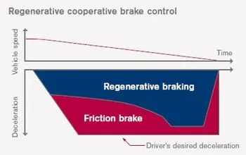
One of the good examples of brake co-ordination is EDIB (Electric Driven Intelligent Brake) which is found in Nissan Leaf.
- EDIB controls the optimization of the regenerative brake and regular friction brake (hydraulic brake) to meet the adequate braking force and maintain regeneration level high as much as possible.
- At higher speed both friction and regenerative brakes are applied, where friction brakes contribute the majority portion.
- At low speeds , the regenerative braking takes higher portion to convert more kinetic energy during deceleration into electrical energy.
Q3. Make a MATLAB program which plots contour of given motor speed, torque and efficiency values. Attach the code as a .m file attach a screenshot of all the plots.
Soln:
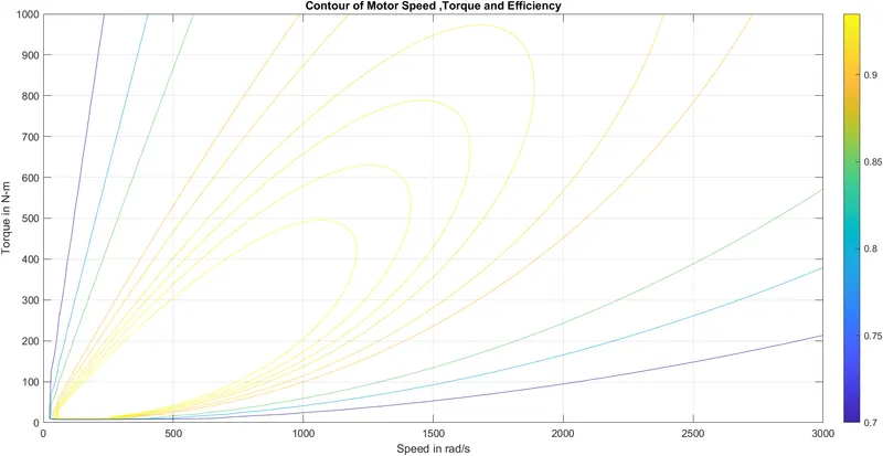
Generally contour plot of electric motor is used to give speed and torque combinations at different efficiencies. To plot contour it is necessary to consider the losses that occur in the motor , which are iron or core losses, Cu-losses, windage losses .
A MATLAB program is created with to plot contour from given data of motor speed , torque and efficiency values-
clear all;

clc;

% defining speed and torque ranges

w=linspace(0,3000);            % motor speed in rad/s

t=linspace(0,1000);               % torque in N-m

%motor loss constants

Kc=0.1;                             %  copper loss constant

Ki=0.009;                           %  iron loss constant

Kw=0.00001;                      %  windage loss constant

Cl=30;                               %  Constant motor loss

[W,T]=meshgrid(w,t);          % making a mesh grid

Pout=(W.*T);                     % output power= speed x torque

A=(T.^2)*Kc;                      % copper losses

B=W*Ki;                            % iron losses

C=(W.^3)*Kw;                    % windage losses

Pinput=Pout+A+B+C+Cl;   % input power= output power+ losses

Z=Pout./Pinput;                 % efficiency

% array of efficiency values for which contour will be plotted

e=[0.70,0.80,0.85,0.90,0.91,0.92,0.925,0.93,0.935];

%  contour plot

contour(W,T,Z,e);

xlabel('Speed in rad/s');ylabel('Torque in N-m');

title('Contour of Motor Speed ,Torque and Efficiency');

grid on

colorbar

hold on;
After running the script file, the contour is achieved as follows-