Week-11 Challenge: Braking
1.For a defined driving cycle, calculate the energy required for braking:
Drive Cycle :
| Drive Cycle | |
| Time | Velocity(Kmph) |
| 1 | 0 |
| 2 | 0 |
| 3 | 0 |
| 4 | 0 |
| 5 | 1 |
| 6 | 1 |
| 7 | 1 |
| 8 | 1 |
| 9 | 2 |
| 10 | 2 |
| 11 | 3 |
| 12 | 3 |
| 13 | 4 |
| 14 | 4 |
| 15 | 5 |
| 16 | 5 |
| 17 | 6 |
| 18 | 6 |
| 19 | 7 |
| 20 | 8 |
| 21 | 9 |
| 22 | 10 |
| 23 | 11 |
| 24 | 12 |
| 25 | 13 |
| 26 | 14 |
| 27 | 15 |
| 28 | 16 |
| 29 | 17 |
| 30 | 18 |
| 31 | 19 |
| 32 | 20 |
| 33 | 21 |
| 34 | 22 |
| 35 | 23 |
| 36 | 24 |
| 37 | 25 |
| 38 | 26 |
| 39 | 26 |
| 40 | 27 |
| 41 | 27 |
| 42 | 27 |
| 43 | 28 |
| 44 | 29 |
| 45 | 30 |
| 46 | 31 |
| 47 | 31 |
| 48 | 32 |
| 49 | 33 |
| 50 | 34 |
| 51 | 35 |
| 52 | 36 |
| 53 | 37 |
| 54 | 38 |
| 55 | 39 |
| 56 | 40 |
| 57 | 41 |
| 58 | 41 |
| 59 | 41 |
| 60 | 42 |
| 61 | 43 |
| 62 | 44 |
| 63 | 45 |
| 64 | 46 |
| 65 | 47 |
| 66 | 48 |
| 67 | 49 |
| 68 | 50 |
| 69 | 51 |
| 70 | 51 |
| 71 | 52 |
| 72 | 53 |
| 73 | 55 |
| 74 | 56 |
| 75 | 57 |
| 76 | 59 |
| 77 | 60 |
| 78 | 60 |
| 79 | 60 |
| 80 | 56 |
| 81 | 55 |
| 82 | 54 |
| 83 | 53 |
| 84 | 52 |
| 85 | 51 |
| 86 | 48 |
| 87 | 46 |
| 88 | 44 |
| 89 | 42 |
| 90 | 40 |
| 91 | 39 |
| 92 | 37 |
| 93 | 35 |
| 94 | 31 |
| 95 | 30 |
| 96 | 29 |
| 97 | 28 |
| 98 | 25 |
| 99 | 20 |
| 100 | 15 |
| 101 | 14 |
| 102 | 12 |
| 103 | 10 |
| 104 | 7 |
| 105 | 5 |
| 106 | 2 |
| 107 | 0 |
| 108 | 0 |
| 109 | 0 |
| 110 | 0 |
| 111 | 1 |
| 112 | 2 |
| 113 | 3 |
| 114 | 4 |
| 115 | 5 |
| 116 | 6 |
| 117 | 7 |
| 118 | 8 |
| 119 | 9 |
| 120 | 10 |
| 121 | 11 |
| 122 | 13 |
| 123 | 15 |
| 124 | 16 |
| 125 | 17 |
| 126 | 19 |
| 127 | 21 |
| 128 | 26 |
| 129 | 27 |
| 130 | 29 |
| 131 | 34 |
| 132 | 34 |
| 133 | 36 |
| 134 | 38 |
| 135 | 39 |
| 136 | 42 |
| 137 | 45 |
| 138 | 47 |
| 139 | 50 |
| 140 | 56 |
| 141 | 62 |
| 142 | 68 |
| 143 | 72 |
| 144 | 75 |
| 145 | 86 |
| 146 | 87 |
| 147 | 88 |
| 148 | 90 |
| 149 | 91 |
| 150 | 91 |
| 151 | 92 |
| 152 | 92 |
| 153 | 93 |
| 154 | 93 |
| 155 | 94 |
| 156 | 94 |
| 157 | 95 |
| 158 | 95 |
| 159 | 96 |
| 160 | 96 |
| 161 | 97 |
| 162 | 98 |
| 163 | 99 |
| 164 | 100 |
| 165 | 97 |
| 166 | 95 |
| 167 | 92 |
| 168 | 89 |
| 169 | 87 |
| 170 | 85 |
| 171 | 82 |
| 172 | 80 |
| 173 | 75 |
| 174 | 70 |
| 175 | 65 |
| 176 | 60 |
| 177 | 54 |
| 178 | 53 |
| 179 | 57 |
| 180 | 50 |
| 181 | 43 |
| 182 | 42 |
| 183 | 41 |
| 184 | 40 |
| 185 | 38 |
| 186 | 36 |
| 187 | 31 |
| 188 | 30 |
| 189 | 29 |
| 190 | 25 |
| 191 | 24 |
| 192 | 23 |
| 193 | 19 |
| 194 | 18 |
| 195 | 15 |
| 196 | 12 |
| 197 | 10 |
| 198 | 8 |
| 199 | 5 |
| 200 | 0 |
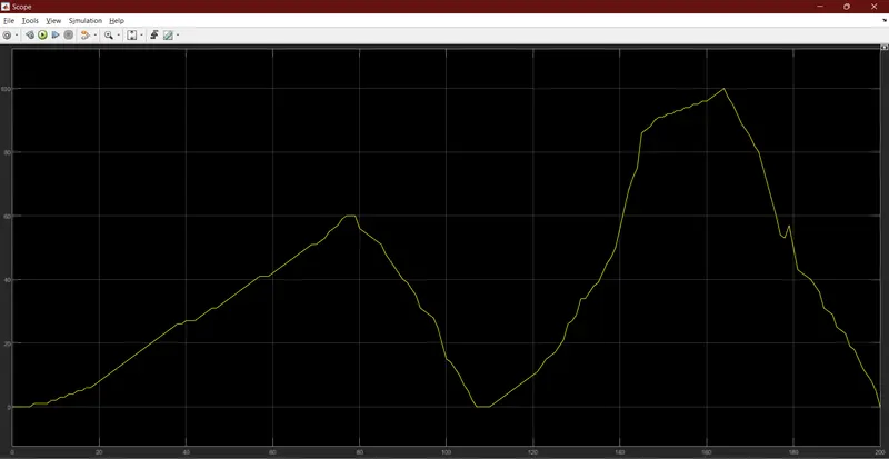
Drive Cycle Graph:
Braking Energy Calculations:
To Find the Power needed for Braking
Bp=1/2 mv^2
v=Vi-Vf
Velocity should be in m/s
To Find the Braking Energy
BE=Bp*Time taken for decelleration in joules
to Find energy in KWH
BP= BE*Time in Hours/1000

Result:
Thus total energy needed for braking is 3.212 KWH
2.Why electric motor can’t develop braking torque at high speed similar to starting? How electric and mechanical brakes are coordinated?
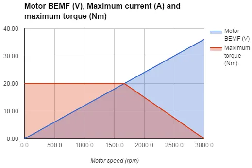
The reason is that no matter how much the current loop wants to increase current (proportional to torque) by increasing the PWM duty cycle of the power stage, the Vmotor is too close to Vbemf and therefore current can't increase more.
Whenever Friction torque + Additional loads = Motor Torque, the load remain in equilibrium (does not move, or moves under constant speed). Whenever Friction torque + Additional loads < Motor Torque, the load accelerates (Motor torque - Friction torque - Additional loads = Acceleration torque > 0). Al high speeds, the BEMF is so close to Vbus that the applicable Motor torque gets limited. Then, the bigger the Friction torque + Additional load is, the smaller the Acceleration torque becomes.
To Overcome this :
1) Increase DC bus voltage.
2) Unlimit system acceleration.
3) Use a motor with less resistance and lower back EMF proportion.
Thus the motor Could not develop high torque while Braking.
How Mechanical and Electric brakes are Corelated:
Conventional Brakes
Braking and the Hydraulic System
Before we dive into the difference between car brakes, let’s describe the hydraulics behind braking. The hydraulic brake circuit consists of a fluid-filled master cylinder, which connects to a separate slave cylinder. The brake pedal connects to the master cylinder and when pushed, depresses the piston in the master cylinder, forcing fluid along connected pipes. The fluid reaches the slave cylinders at each wheel, which in turn forces the piston to apply the brakes.
The surface area of the combined slave pistons, where the brake-pedal force is applied, is greater than that of the master-cylinder piston. Hence, the master piston has to travel a greater distance to move the slave pistons compared to the fraction of distance required by the slave pistons to apply the brakes. This setup allows for the exertion of a large force by the brakes, comparable to how a long-handled lever can lift a heavy object a short distance.
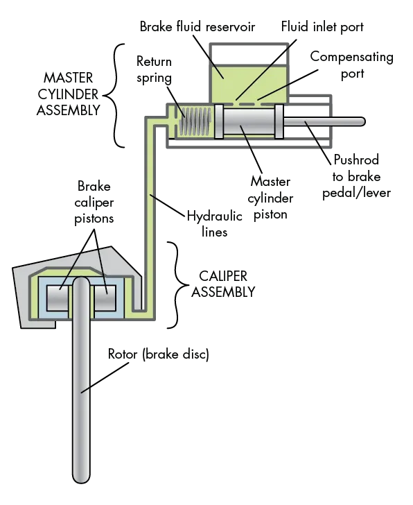
The hydraulic system used during braking delivers hydraulic fluid from the reservoir to the brake caliper pistons to slow down and stop the brake disc.
In most modern cars, the master cylinders use twin hydraulic circuits in tandem for redundancy purposes. The circuits can be arranged to control different pairings of breaks: one circuit for the front pair and the other for the back pair; or one circuit for one in front and one in back, and the other circuit for the other side.
By design, rear brakes are less powerful to prevent the rear wheels from locking and skidding. A load-sensitive pressure-limiting valve prevents locking in most cars by controlling high rises in hydraulic pressure. Limiting valves help prevent brake locking situations, along with anti-lock brake systems which monitor wheel locking. Modern cars also apply power-assisted brakes.
A servo unit, using the pressure difference between the partial vacuum in the inlet manifold and the outside air, provides braking assistance via a pipe connection to the inlet manifold. The servo is fitted between the master cylinder and the brake pedal. When a driver pushes on the brake pedal, it in turn pushes on the master-cylinder piston and a set of air valves.
A large diaphragm connects to a master-cylinder piston. Prior to applying the brakes, both sides of the diaphragm are exposed to the vacuum from the manifold. Applying the brakes closes the valves that link the rear side of the diaphragm to the manifold and opens a valve to let in outside air. The high pressure of the outside air pushes the diaphragm forward on the master-cylinder piston to assist the braking effort. If the brake pedal is kept in place, the air valve stops drawing on the outside air, keeping the brake pressure constant.
Disc and Drum Brakes
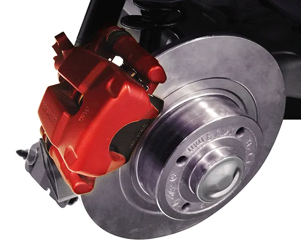
The image above is an example of a typical disc brake with a caliper that applies pressure to the friction or brake pads. This friction force slows down the wheel and allows the car to stop.
The pistons only move a small distance to apply the brakes, and when released, the friction pads barely clear the disc since they have no return springs. The small gap is maintained by allowing the pistons to slip forward gradually as the pads become worn down. Rubber sealing rings around the pistons make this possible, preventing constant brake adjustment. Modern cars use wear sensors to indicate when pads need replacement.
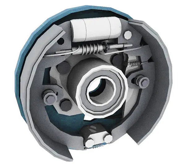
Inside the drum brake are two curved brake shoes. When hydraulic pressure is applied, the brake shoes are forced outward, causing the linings to apply a friction force against the drum. The drum is connected to the wheel and slows down as a result.. The drum is connected to the wheel and slows down as a result.
The rear wheels typically use drum brakes, which use a hollow drum that turns with the wheel. A stationary back plate covers the open back of the drum. The back plate has two curved brake shoes carrying friction linings. Hydraulic pressure provided by pistons in the brake wheel force the shoes outward, causing the linings to press against the inside drum and thus making the wheel slow down or stop completely. As opposed to disc brakes, return springs are used to pull the brake shoes back when the brake is released. Drum brakes have a tendency to fade if applied repeatedly in a short time—they heat up and lose their efficiency until the heat dissipates.
Regenerative Braking
Creating Energy
As mentioned earlier, a conventional braking system’s disc and drum brakes use friction to slow and stop modern cars. However, most hybrid and electric vehicles use regenerative brakes due to the added benefit of recharging electric batteries.
Vehicles with regenerative brakes achieve braking by driving the motor in reverse. As the driver steps on the brake pedal, the vehicle’s electric motor is placed in reverse mode, causing it to run backwards. This operation not only slows the car’s wheels, but also acts an electric generator for the car. The reverse motion produces electricity that feeds into the car’s battery. Hybrid and electric vehicles also have friction brakes that act as a backup system when the regenerative braking is not supplying enough power to stop the vehicle.
Reverse motor motion can be achieved by using the vehicle’s own momentum. The electronic circuitry and the car’s onboard computer determine when to use the conventional frictional brake system or whether to put the motor into reverse. A slight reduction in the car’s momentum, determined by the driver’s force on the pedal, causes the vehicle’s electronics to activate the regenerative brakes and place the motor in reverse. In contrast, if the vehicle needs to come to a quick stop, to avoid a collision for example, the conventional brakes will be engaged.
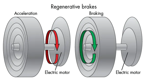
When the electric motor reverses direction, it becomes a generator that stores the energy in the vehicleâs battery.
A brake controller controls regenerative braking. Brake controllers are electronic devices that determine when, via remote control, braking begins and ends, as well as the speed of application. Similar to an ABS controller that monitors the rotational speed of the wheels in relation one another, the brake controller can calculate how much torque is available to generate electricity as well as monitor wheel speed.
The brake controller directs the electricity produced into the batteries or capacitors during braking. This ensures delivery of optimal amounts of electricity, and prevents overloading of the batteries or capacitors. Ultimately, the brake controller decides which brake system to use. If the required braking force is too great for the regenerative brakes, the brake controller activates the friction brake to avoid possible accidents.
3. Make a MATLAB program which plots contour of given motor speed, torque and efficiency values. Attach the code as a .m file attach a screenshot of all the plots.
Code With Given Values:
clear all
close all
clc

W= linspace(0,1800);
T= linspace(0,500);

kc = 0.23;
ki= 0.01;
kw= 0.000045;

[X,Y]= meshgrid(W,T);
copper_loss = (Y.^2)*kc;
iron_loss = X*ki;
windage_loss = (X.^3)*kw;
K=50;
output_power=X.*Y;
input_power=(copper_loss)+(iron_loss)+(windage_loss)+(output_power)+K;
Eff = (output_power)./(input_power);
n = linspace(0.7,0.95,10);
contourf (X,Y,Eff,n);
title('Speed Torque Characterestics')
xlabel('Speed rad/s')
ylabel('Torque n-m')
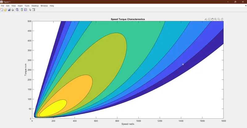
Contour Plot:
Result:
Thus by the Contour Plot we Recognize that the motor operates at higher efficiency for certain time period which is mentioned by yellow region.