Week-11 Challenge: Braking
AIM:
- To calculate the energy required for braking for a defined driving cycle.
- To explain why electric motor can’t develop braking torque at high speed similar to starting and how electric and mechanical brakes are coordinated.
- To make a MATLAB program which plots contour of given motor speed, torque and efficiency values.
BODY OF CONTENT:
Braking system in electric vehicles:
A moving vehicle possesses kinetic energy and to stop the vehicle, the energy of the moving vehicle has to be converted into another form. The friction brake system in a conventional vehicle dissipates kinetic energy in the form of heat energy.
If the complete kinetic energy is transformed into another form of energy, then the vehicle stops. As a result of friction, heat energy is being generated in the braking system when the vehicle brakes.Disc brakes and drum brakes are the widely used brake systems in a internal combustion engine vehicle.
Engine braking:
The term "engine braking" refers to the braking effect that occurs in gasoline engines when the accelerator pedal is released. This causes fuel injection to cease and the throttle valve to close almost completely, greatly restricting forced airflow from, for example, a turbocharger. The restriction causes a strong manifold vacuum which the cylinders have to work against, sapping much of the potential energy out of the system over time and producing the majority of the engine-braking effect. This vacuum manifold effect can often be amplified by a down-shift, which induces a faster spinning drivechain to engage with the engine
Compression release brake
A Compression release brake (also known as a Jacobs brake or "jake brake"), is the type of brake most commonly confused with real engine braking; it is used mainly in large diesel trucks and works by opening the exhaust valves at the top of the compression stroke, so the large amount of energy stored in that compressed air is not returned to the crankshaft, but is released into the atmosphere.
Normally, during the compression stroke, energy is used as the upward-traveling piston compresses air in the cylinder; the compressed air then acts as a compressed spring and pushes the piston back down. However, with the jake brake in operation, the compressed air is suddenly released just before the piston begins its downward travel. (This sudden release of compressed air creates audible sound waves similar to the expanding gases escaping from the muzzle of a firearm.) Having lost the energy stored within the compressed air, there is no "spring back" so the engine must expend yet more energy pulling the piston back down again.
This type of brake is banned or restricted in many residential locations because (unless properly muffled) it creates a machine-gun-like sound loud enough to disturb the peace, including waking people at night. It is very effective, however, and creates immense amounts of braking force which significantly extends friction brake life – a 565 hp (421 kW) diesel engine can produce up to 600 hp (450 kW) of braking power at 2,100 RPM.
Electromagnetic brakes:
Electromagnetic brakes are likewise often used where an electric motor is already part of the machinery. For example, many hybrid gasoline/electric vehicles use the electric motor as a generator to charge electric batteries and also as a regenerative brake. Some diesel/electric railroad locomotives use the electric motors to generate electricity which is then sent to a resistor bank and dumped as heat. Some vehicles, such as some transit buses, do not already have an electric motor but use a secondary "retarder" brake that is effectively a generator with an internal short circuit. Related types of such a brake are eddy current brakes and electromechanical brakes (which actually are magnetically driven friction brakes, but nowadays are often just called "electromagnetic brakes" as well).
Electromagnetic brakes slow an object through electromagnetic induction which creates resistance and in turn either heat or electricity. Friction brakes apply pressure on two separate objects to slow the vehicle in a controlled manner.
Power assisted brakes:
Many cars also have power assistance to reduce the effort needed to apply the brakes.
Usually the source of power is the pressure difference between the partial vacuum in the inlet manifold and the outside air.
The servo unit that provides the assistance has a pipe connection to the inlet manifold.
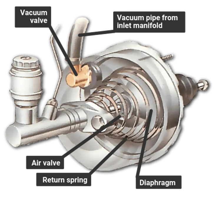
A direct-acting servo is fitted between the brake pedal and the master cylinder. The pedal can work the master cylinder directly if the servo fails or if the engine is not running.
A direct-acting servo is fitted between the brake pedal and the master cylinder. The brake pedal pushes a rod that in turn pushes the master-cylinder piston.
But the brake pedal also works on a set of air valves, and there is a large rubber diaphragm connected to the master-cylinder piston.
When the brakes are off, both sides of the diaphragm are exposed to the vacuum from the manifold.
Pressing the brake pedal closes the valve linking the rear side of the diaphragm to the manifold, and opens a valve that lets in air from outside.
The higher pressure of the outside air forces the diaphragm forward to push on the master-cylinder piston, and thereby assists the braking effort.
If the pedal is then held, and pressed no further, the air valve admits no more air from outside, so the pressure on the brakes remains the same.
When the pedal is released, the space behind the diaphragm is reopened to the manifold, so the pressure drops and the diaphragm falls back.
If the vacuum fails because the engine stops, for example the brakes still work because there is a normal mechanical link between the pedal and the master cylinder. But much more force must be exerted on the brake pedal to apply them.
Regenerative braking:
Along with the friction brake system, another type of braking is also possible in an electric vehicle. It is known as regenerative braking.
In regenerative braking, the energy that would have been lost as heat during braking is tapped and stored back in the battery. The electric machine that propels the vehicle acts as a generator during the deceleration and braking to convert the kinetic energy to electric energy.
Power electronics converters with bidirectional power flow help out here to store the electric energy generated during braking in an electric vehicle.When the vehicle decelerates, the electric motor acts as a generator and generates electricity from the kinetic energy of the vehicle.
Electronic brake force distribution:
Electronic brakeforce distribution (EBD or EBFD) or electronic brakeforce limitation (EBL) is an automobile brake technology that automatically varies the amount of force applied to each of a vehicle's wheels, based on road conditions, speed, loading, etc. Always coupled with anti-lock braking systems (ABS), EBD can apply more or less braking pressure to each wheel in order to maximize stopping power whilst maintaining vehicular control.
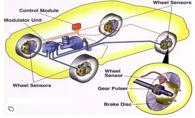
The simple idea behind an EBD system is that it need not be necessary to apply the same amount of braking force on each wheel so as to reduce the speed of the car or bring it to a complete stop. An EBD system makes use of three components which make it tick. The speed sensors, brake force modulators and electronic control unit (ECU).
- 1. Speed Sensor: The speed sensor not only calculates the speed of the car, but the speed of the engine also (RPM). One of the scenarios can be that the speed of the wheel might not be the same as the speed of the car. Such a situation can lead to the wheel(s) skidding. The speed sensors calculate the slip ratio and relay it to ECU.
- 2. Electronic Control Unit: It is a small chip which collects the data from the speed sensors in each wheel and uses the data to calculate the slip ratio (difference between the speed of the car and the rotation of the tyre). Once the slip ratio is determined, it makes use of the brake force modulators to keep the slip ratio within limits.
- 3. Brake Force Modulators: It is the job of these modulators to pump brake fluid into the brake lines and activate the brake cylinders. The brake force applied on each wheel can be modulated.
1. Calculation of the energy required for braking for a defined driving cycle:
For a drive cycle CYC_FTP,
Mass of the vehicle = 1000 kg
Initial velocity (Vi) = 0 kmph
Final velocity (Vf) = 100 kmph
Time for braking from 100 kmph to 0 kmph = 10 seconds
Braking energy required = Kinetic energy produced to reduce the speed from 100 kmph to 0 kmph
Vf = 100 kmph = 27.78 m/s
Kinetic energy = 0.5 * m* (Vf - Vi)^2
= 0.5 * 1000 * (27.78)^2
Braking energy = 385.864 kJ
Braking power = Braking energy/time required
Braking power required = 38.586 kW
2. Why electric motor can’t develop braking torque at high speed similar to starting? How electric and mechanical brakes are coordinated?
This is essentially a process of taking away the kinetic energy of a moving vehicle and transforming that into another form of energy. So far, this has been done through the application of friction.
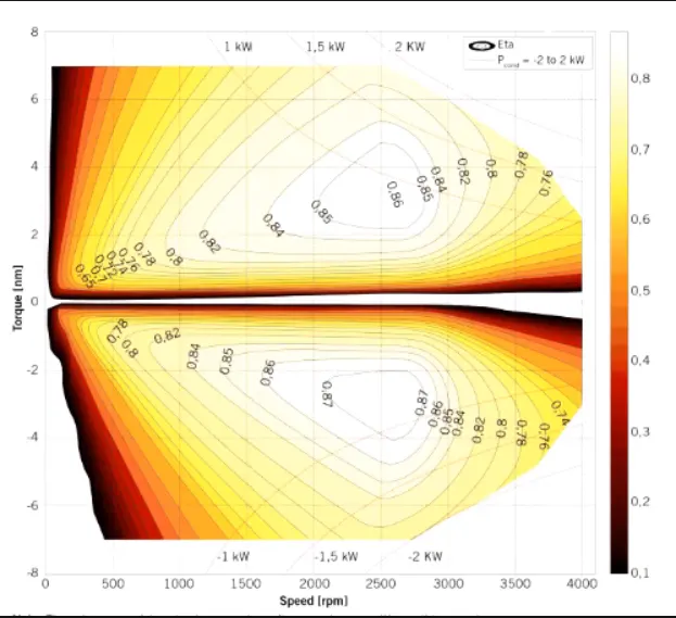
The above diagram is the speed torque characteristics of the motor used in electric vehicle application. The X-axis represents the speed in rpm which is in positive direction and Y-axis represents the Torque in N-m. The upper part of the graph represents the positive torque and the lower part of the graph represents the negative torque.
Case 1: Consider the case where the electric vehicle achieves 0 to 100 kmph in 10 seconds at approximately say 2500 rpm. Here the operating region is in upper quadrant which is acclerating part. The acceleration is achieved gradually at the duration of 10 seconds where the vehicle is operated at peak torque for certain speed range (lower speed range) to get higher acceleration power. Assuming for 1 kW power, the vehicle is operated at peak torque for about 1400 rpm. After 1400 rpm, since the vehicle is operating at a constant power region, the torque required to produce 100 kmph is less than the peak torque.
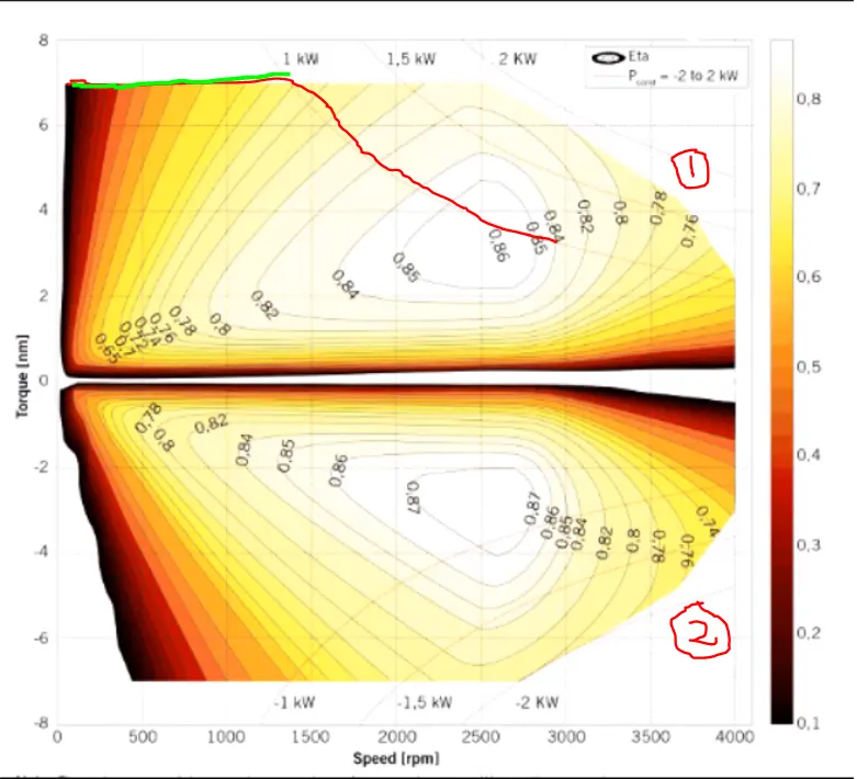
In the above diagram the green line represents the peak torque and the red line represents the constant power region. The 1st quadrant represents the accelerating part and the second quadrant represents the decelerating part. It is easier for the motor to reach from 0 to 100 kmph.
Case 2: Consider the case when the braking is applied where the speed is decelerated from 100 kmph to 0 kmph but less than 10 seconds. When comes to braking part where the torque is negative, the operating point in the positive region is replicated in the negative torque region. In that particular point, the torque is not peak torque and the braking torque developed is -4 N-m in this case.
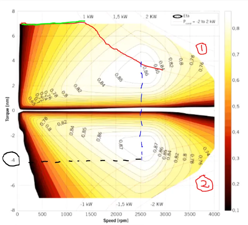
Thus we can conclude that peak acceleration torque and the peak deceleration torque is not same for an electric motor. The peak torque for acceleration at lower speed is higher (In this case it is 7 N-m) whereas the peak torque for deceleration or braking at high speed is lower (In this case it is -4 N-m).
So it cannot be assured that the motor which is producing 7 N-m torque during acceleration can also produce -7 N-m torque during deceleration. Since we are operating the motor in the field weakening region or we are operating the motor above the base speed, it is known that torque value is lower.
It is concluded that braking torque is not as high as the acceleration torque. Thus, the regenarative braking cannot happen so effectively that all the power is restored in the battery.
Brake control strategies:
Brake System of EVs and HEVs
Series Brake — Optimal Feel
Series Brake — Optimal Energy Recovery
Parallel Brake
Antilock Brake System (ABS)
Brake System of EVs and HEVs
Two basic questions arise while considering regenerative braking in EVs and HEVs:
- How to distribute the total braking forces required between the regenerative brake and the mechanical friction brake so as to recover the kinetic energy of the vehicle as much as possible.
- The other is how to distribute the total braking forces on the front and rear axles so as to achieve a steady-state braking.
Basically, there are three different brake control strategies: series braking with optimal braking feel; series braking with optimal energy recovery; and parallel braking.
Series Brake - Optimal Feel:
The control objective is to minimize the stopping distance and optimize the driver’s feel.
Figure 1 illustrates the principle of this braking control strategy. When the commanded deceleration (represented by the braking pedal position) is less than 0.2g, only the regenerative braking on the front wheels is applied, which emulates the engine retarding function in conventional vehicles. When the commanded deceleration is greater than 0.2 g, the braking forces on the front and rear wheels follow the ideal braking forces distribution curve I, as shown in Figure 1 by the thick solid line.
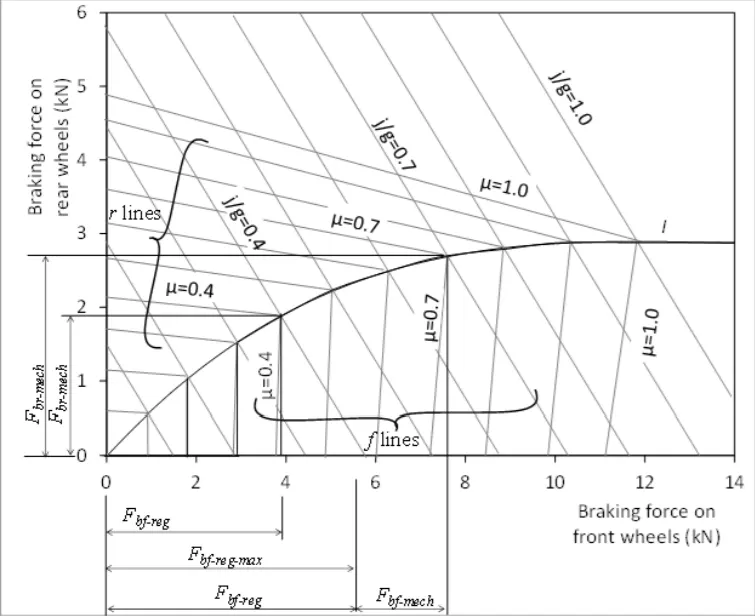
The braking force on the front wheels (driven axle) is divided into two parts: regenerative braking force and mechanically frictional braking force. When the braking force demanded is less than the maximum braking force that the electric motor can produce, only electrically regenerative braking will apply. When the commanded braking force is greater than the available regenerative braking force, the electric motor will operate to produce its maximum braking torque, and the remaining braking force is met by the mechanical brake system. It should be noted that the maximum regenerative braking force produced by an electric motor is closely related to the electric motor’s speed. At low speed (lower than its base speed), the maximum torque is constant. However, at high speed (higher than its base speed), the maximum torque decreases hyperbolically with its speed. Therefore, the mechanical brake torque at a given vehicle deceleration varies with vehicle speed.
Series Brake - Optimal Energy Recovery
The principle of the series braking system with optimal energy recovery is to recover the braking energy as much as possible in the condition of meeting the total braking force demanded for the given deceleration.
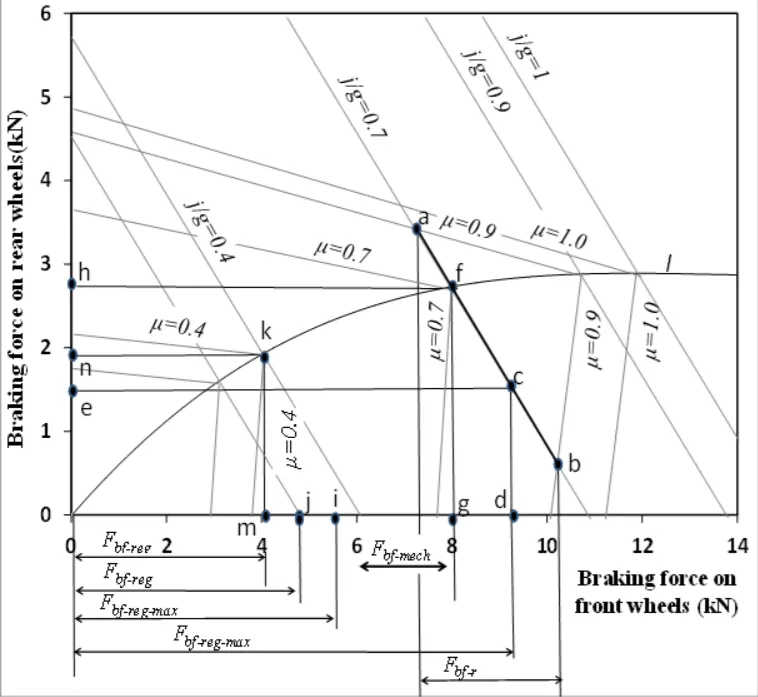
This principle is illustrated in Figure . When the vehicle is braked with an acceleration rate of j /g < μ , the braking forces on the front and rear wheels can be varied in a certain range, as long as the Fbf + Fbr = Mv j is satisfied. This variation range of the front and rear axles is shown in Figure by the thick solid line ab , where μ= 0.9 and j /g = 0.7. In this case, regenerative braking should be used in priority. If the available regenerative braking force (maximum braking force produced by the electric motor) is in this range (point c in Figure , for example), the braking force on the front wheels should be developed only by regenerative braking without mechanical braking. The braking force on the rear wheels, represented by point e , should be developed in order to meet the total braking force requirement. If, on the same road, the available regenerative braking force is less than the value corresponding to point a (e.g. point i in Figure), the electric motor should be controlled to produce its maximum regenerative braking force. The front and rear braking forces should be controlled at point f so as to optimize the driver feel and reduce braking distance. In this case, additional braking force on the front wheels must be developed by mechanical braking by the amount represented by Fbf – mech and the braking force on the rear axle is represented by point h .
When the commanded deceleration rate j /g, is much smaller than the road adhesive coefficient ( j /g = 0.3 in Figure 2 for example), and the regenerative braking force can meet the total braking force demand, only regenerative braking is used without mechanical braking on the front and rear wheels (point j in Figure 2).
When the commanded deceleration rate, j /g is greater than the road adhesive coefficient μ, this commanded deceleration rate will never be reached due to the limitation of the road adhesion. The maximum deceleration that the vehicle can obtain is max ( a/ g)max = μ . The operating point of the front and rear braking forces is on the curve I , corresponding to μ; the operating point is point k and the maximum deceleration rate is j/ g = 0.4.
It should be noted that the series brake with both optimal feel and energy recovery needed active control of both electric regenerative braking and mechanical braking forces on the front and rear wheels. At present, such a braking system is under research and development.
Parallel Brake:
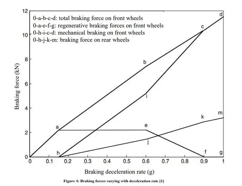
The parallel brake system includes both an electrical (regenerative) brake and a mechanical brake, which produce braking forces is parallel and simultaneously. The operating principle is illustrated in Figure 3, in which regenerative braking is applied
only to the front wheels. The parallel brake system has a conventional mechanical brake which has a fixed ratio of braking force distribution on the front and rear wheels. Regenerative braking adds additional braking force to the front wheels, resulting in the total braking force distribution curve. The mechanical braking forces on the front and rear axles are proportional to the hydraulic pressure in the master cylinder. The regenerative braking force developed by the electric motor is a function of the hydraulic pressure of the master cylinder, and therefore a function of vehicle deceleration. Because the regenerative braking force available is a function of motor speed and because almost no kinetic energy can be recovered at low motor speed, the regenerative braking force at high vehicle deceleration (e.g., a /g = 0.9 ) is designed to be zero so as to maintain braking balance.
When the demanded deceleration is less than this deceleration, regenerative braking is effective. When the braking deceleration commanded is less than a given value, say 0.15g , only regenerative braking is applied. This emulates the engine retarding in a conventional vehicle.
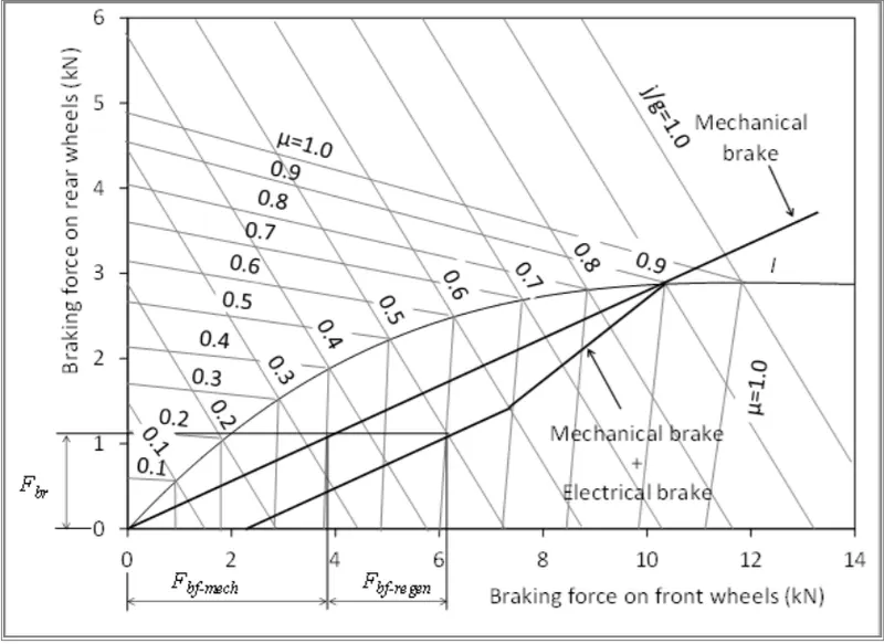
Figure below shows the total braking force, regenerative braking force, and mechanical braking force on the front wheels as well as the braking force on the rear wheels in the parallel braking system of a passenger car. The parallel braking system does not need an electronically controlled mechanical brake system. A pressure sensor senses the hydraulic pressure in the master cylinder, which represents the deceleration demand. The pressure signal is regulated and sent to the electric motor controller to control the electric motor to produce the demanded braking torque. Compared with the series braking of both optimal feel and energy recovery, the parallel braking system has a much simpler construction and control system. However, the driver’s feeling, and amount of energy recovered are compromised.
Antilock Brake System (ABS):
Anti-lock braking systems, which are also referred to as anti-skid braking systems, are designed to prevent this from happening. Essentially, they keep a vehicle’s wheels from locking up when braking. The modern abs system allows steering during braking which gives more control over the vehicle in case of sudden braking. The main advantages of using ABS system in vehicle is that it provides better control over the vehicle and decreases stopping distance on dry and slippery surfaces. Since in ABS installed vehicle the chance of skidding is very less and hence it provides a better steering control during braking. Without ABS system, even a professional driver can fail to prevent the skidding of the vehicle on dry and slippery surfaces during sudden braking. But with ABS system, a normal person can easily prevent the skidding of the vehicle and get better steering control during braking.
It works on the principle of threshold braking and cadence braking. Cadence braking and threshold braking is a technique in which a driver applies the brakes and releases it before locking up the wheel and then applies the brakes and releases it again before locking. This process of applying and releasing the brakes on the wheel is done in pulse form to prevent it from locking and stop skidding of the vehicle. The driver practices this technique to achieve better control over the vehicle during instant braking and stop skidding of the vehicle. The ABS system automatically does this cadence braking to prevent locking of wheel and skidding of vehicle when brakes are applied.
3. MATLAB program which plots contour of given motor speed, torque and efficiency values.
clear all
close all
clc
%Speed and torque in x & y axis
x = linspace(1,1000);
y = linspace(1,250);

%motor loss constants
kc = 0.2;
ki = 0.008;
kw = 0.00001;
con = 20;

%mesh
[X,Y] = meshgrid(x,y);

%output power = speed * Torque
OP = (X.*Y);
%copper loss
B = (Y.^2)*kc;
%iron loss
C = X*ki;
%windage loss
D = (X.^3)*kw;

%input power = output power + losses
IP = OP + B + C + D + con;

%efficiency = output power/input power
Z = OP./IP;
V = [0.7, 0.8, 0.85, 0.9, 0.91, 0.92, 0.925, 0.93];
box off;
grid off;
contour(X,Y,Z,V);
xlabel('Speed in rad/sec');
ylabel('Torque in N-m');
title('efficiency contour of electric motor')
hold on;
V = [8000,10000];
contour(X,Y,OP,V);
Explanation:
- The random values of speed and torque values are given in the 'X' and 'Y' axis using 'linspace' command.
- Motor losses are assumed to some values which includes copper loss, windage loss, iron loss and a constant.
- The speed and torque values are arranged as a 2-D co-ordinates using 'meshgrid' command.
- The output power, iron loss, copper loss and windage loss are calculated using formulas given.
Copper loss = kc * T^2
Iron loss = ki * ω
Windage loss = kw * ω^2
Output power = torque*speed
input power = output power + losses
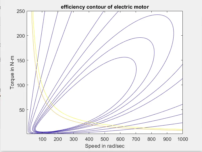
efficiency = output power/input power - Efficiencies are plotted in the range of 70%,80%,85%,90%,91%,92%,92.5%,93%. V is the mapping of efficiencies in the contour plot.
- Contour plot for 8kW and 10kW are plotted.
Result:
Conclusion:
1. For a defined driving cycle, the energy required for braking is calculated and the braking system used in electric vehicles is explained from which it is concluded that
Most electric cars use both mechanical and regenerative braking systems together. An electric car brake system recuperates the energy that would have been lost during braking and stores it in the battery. This provides an additional 10 to 25% range to the vehicle.
In addition to the energy-saving, the regenerative braking technology helps out to improve the life of the friction brake system as well.
- The electric car brake system uses both friction and regenerative braking technologies
- 100% regenerative braking is not yet implemented in an electric car
- One pedal driving vehicles use more effective regenerative braking
- Friction braking is also necessary for an electric car
2. Why electric motor can’t develop braking torque at high speed similar to starting is explained and it is concluded that braking torque is not as high as the acceleration torque. Thus, the regenarative braking cannot happen so effectively that all the power is restored in the battery.
3. MATLAB program which plots contour of given motor speed, torque and efficiency values is made and results are obtained and it is concluded that innermost efficiency curves are higher and the outer curves are lower.
References:
https://nptel.ac.in/content/storage2/courses/108103009/download/M11.pdf
https://getelectricvehicle.com/brake-system-electric-vehicles/
https://www.mechanicalbooster.com/2017/08/anti-lock-braking-system.html