Week-11 Challenge: Braking
- For a defined driving cycle, calculate the energy required for braking.
- Why electric motor can’t develop braking torque at a high speed similar to starting? How electric and mechanical brakes are coordinated?
- Make a MATLAB program that plots the contour of given motor speed, torque and efficiency values. Attach the code as a .m file attach a screenshot of all the plots.
Aim-
Calculation Of Braking Energy for the required Drive cycle
Braking of the Vehicle is required to decelerate the vehicle which requires certain energy that will get the vehicle to a standstill by dissipating the thermal energy from the brakes and here we are going to calculate the braking energy that has been required for the vehicle in a particular Drive cycle which has been created using the Excel file has been shown below.
Kinetic energy is the force that keeps the vehicle moving. This energy is provided by the engine to accelerate the vehicle from a standstill to the desired speed. Kinetic energy is dissipated as heat by the brakes during the application of breaks. The kinetic energy of a vehicle during braking is given by
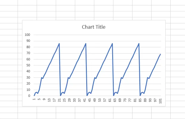
The above sample Drive cycle has been used for calculating the Breaking energy of the vehicle where the excel of the plot is used
clc
%Read the Drive Cycle data from given .xls file
DC=xlsread('Braking.xlsx');
T=DC(:,1); %Time in seconds
S=DC(:,2); %Speed in Kmph
%other data
m = 1000; %mass in Kg
V=S./3.6; %Speed in m/s
%To create an Array to store values for Deceleration & Braking Energy
Z=length(T);
deceleration=zeros(1,Z);
acceleration=zeros(1,Z);
BE=zeros(1,Z);
AE=zeros(1,Z);
for i=1:(length(T)-1)
if V(i)>V(i+1)
BE(i)=0.5*(V(i)-V(i+1))^2; %Braking Energy in Joules
speed_decrease(i)=V(i+1)-V(i);
deceleration(i)=speed_decrease(i);
%since Time Delta is 1s Acc/dec=V/T..m/s^2, where T=1
end
if V(i)<V(i+1)
AE(i)=0.5*m*(V(i)-V(i+1))^2; %Accelerating Energy in Joules
speed_increase(i)=V(i+1)-V(i);
acceleration(i)=speed_increase(i);
end
end
%Total Braking Energy in KJ
B_E=(sum(BE)/1000);
%Total Acceleration Energy in KJ
A_E=(sum(AE)/1000);
%Plotting Curves
figure(1)
subplot(2,1,1)
plot(T,S,'color','b')
xlabel('Time(s)')
ylabel('Speed(Kmph)')
title('Drive Cycle')
subplot(2,1,2)
plot(T,deceleration,'color','r')
hold on
plot(T,acceleration,'color','g')
xlabel('Time(s)')
ylabel('Acc/Dec(m/s^2)')
title('Acceleration-Deceleration')
figure(2)
plot(T,BE)
hold on
plot(T,AE)
xlabel('Time(s)')
ylabel('Energy(J)')
title('Energy consumed during Braking & required for acelerating throughout Drive Cycle')
legend('Braking Energy','Accelerating Energy')
fprintf('Total Energy consumed during Braking is %f KJ',B_E)
disp(' ')
fprintf('Total Energy consumed during Acceleration is %f KJ',A_E)
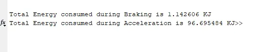
The Brake energy consumed for the given Drive cycle is shown below
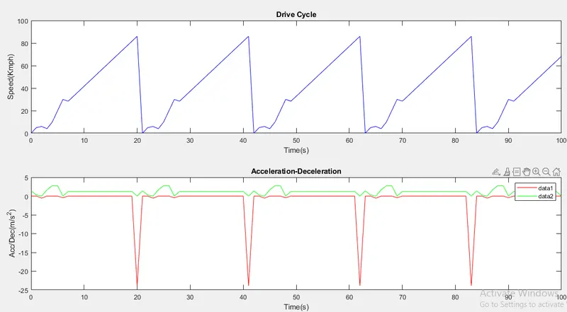
the output plot of the model is shown below
AIM-
Why electric motor can’t develop braking torque at a high speed similar to starting? How electric and mechanical brakes are coordinated?
The electric motor can't develop braking torque at high speed similar to starting because once the electric supply is pulled off from the motor, it acts as a generator and due to the flux weakening effect of the electric generator, the generator produces low torque as expected.
In EV application there is a motor-generator, and a battery pack to supply power, as the electric current travels through the motor within a magnetic field, it generates a force. The more current applied, the more the motor will spin. For Regenerative Braking a motor will act as a generator i.e. the direction of the electric flow is reversed, the electric motor will rather than take in current to spin the armature, the armature is spun through the field by the deceleration of the vehicle. The electricity produced is used to recharge the battery, and the motor can switch between powering the car and regenerating electricity as fast as the driver can accelerate and lift off. As the motor reverse increase, it also creates "back electromotive force" or "back EMF." The faster the motor spins, the more back EMF is created, reducing the effective voltage it can deliver. But at zero RPM, all of the electricity the motor creates from the time electric power is applied becomes instant torque—without any back EMF to reduce its output. The higher the revs, the more back EMF, meaning that the instantaneous torque effect diminishes.
The reason behind this no matter how much the current loop wants to increase current (proportional to torque) by increasing the PWM duty cycle of the power stage, the V motor is too close to Vbemf and therefore current can't increase more.
The most common form of regenerative brake involves using an electric motor as an electric generator. The working of the regenerative braking system depends upon the working principle of an electric motor, which is an important component of the system. The electric motor gets activated when some electric current is passed through it. But, when some external force is applied to activate the motor (during the braking), then it behaves as a generator and generates electricity. This means that whenever the motor runs in one direction, the electric energy gets converted into mechanical energy, which is then used to accelerate the vehicle, and whenever the motor runs in the opposite direction, it performs the functions of a generator, which then converts mechanical energy into electrical energy, which makes it possible to utilize the rotational force of the driving axle to turn the electric motors, which results in regenerating electric energy for storage in the battery and simultaneously reducing the speed of the car with the regenerative resistance of the electric motors. This electricity is then used for recharging the battery.
How electric and mechanical brakes are coordinated?
A Regenerative Braking system is used to convert waste energy(heat) into useful energy(stored in a battery) with the help of a motor that acts as a generator when reversed. There are certain limitations with RBS i.e. the electric motor is unable to provide all the brake torque necessary for large decelerations. In the case of braking, if the braking torque is applied only to one axle, there are chances stability and manoeuvrability issues can occur. So to avoid such a situation regenerative braking is operated in conjunction with a friction(mechanical) brake system.
The RBS and Mechanical Brake system are used in a strategic manner which is called Brake Control Strategy and there are two types
1. Series Brake Control
In this type of control system, the Mechanical Brakes and Regenerative(Electric) Brakes are applied one after the other. We can only apply one brake system at a time either RBS or Mechanical brakes.
2. Parallel Brake Control
In this type of brake control system, both the Mechanical Brakes and RBS are applied simultaneously.
AIM
Make a MATLAB program that plots the contour of given motor speed, torque and efficiency values. Attach the code as a .m file attach a screenshot of all the plots.
For Plotting the contour of the Motor we have to know the various losses that are occurring in the motor like
Copper Losses
Iron Losses
Windage losses
Constant losses
By adding all the losses we can get the equation as
`Kc*T^2+Ki*w+Kw*w^3+C`
By using the input and the output power we can calculate the efficiency of the motor, and the contour plot of the motor has been drawn by using the below MATLAB program
%Efficiency for Electric Motors

clc
x = linspace(1,1000);              % Speed in rad/s
y = linspace(1,250);                  % Torque in Nm

%Motor loss constants

Kc = 0.2;            %Copper Loss
Ki = 0.008;            %Iron Loss
Kw = 0.0001;                  %Winding Losses
C = 20;                %Constant Motor Losses
[X,Y] = meshgrid(x,y);
Output_Power = (X.*Y);
C_1 = (Y.^2)*Kc;              %Copper Loss
I_1 = (X*Ki);           %Iron Loss
W_1 = (X.^3)*Kw;          %Winding Loss
Input_Power = Output_Power+C_1+I_1+W_1+C;
Z = Output_Power./Input_Power;
V = [0.70,0.80,0.85,0.90,0.91,0.92,0.925,0.93];
box off
grid off
[c,h] = contour(X,Y,Z,V);
xlabel('Speed(rad/s)');
ylabel('Torque(N/m)');
clabel(c,h);
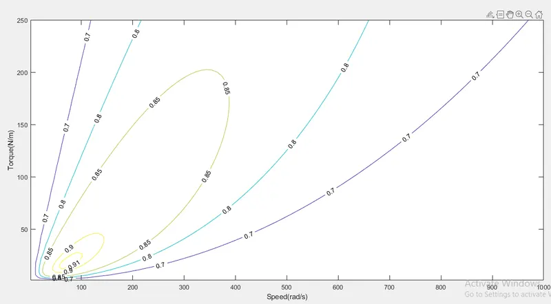
In the above program, we are plotting speed Vs Torque characteristics with efficiency values then we are finding the losses of the motor for finding the efficiency
Contour plots are the way to show a three-dimensional(3-D) surface in the two-dimensional(2-D) plane. It graphs two predictor variables X Y on the y-axis and a response variable Z as contours. In our simulation, we can observe the X-axis as the Speed(rad/s) and Y-axis as the Torque(N-m).
the resultant output polt of the model has been shown below.