Week-11 Challenge: Braking
1.For a defined driving cycle, calculate the energy required for braking.
Braking is the process of controlling the velocity of an object by inhibiting its motion. An object in motion possesses kinetic energy and to bring the object to a stop this kinetic energy must be removed.
Removing the kinetic energy can be accomplished by dissipating the energy to the atmosphere through friction or by converting it into another form of energy. The most common type of braking is a mechanical brake which inhibits motion through friction brake pads. A mechanical brake applies a friction force to convert the kinetic energy of the vehicle into thermal energy which then dissipates into the atmosphere.Braking systems which don't use friction are referred to a regenerative braking systems system (RBSs). In RBSs, the kinetic energy is converted into other forms of useful energy, which can be stored for later use, increasing fuel efficiency.
As with any system, the process of braking must follow the principal of conservation of energy. Energy cannot be created or destroyed but only converted from one form to another,
`sum`Ein=`sum`Eout
The energy present in an object in motion from braking is given by the following equation:
Ekinetic=(mv2)2">Ekinetic=`(1/2)m(Vi-Vf)^2`where,
• m">m is the mass of the object in kilograms (kg).
• Vi is the initial velocity and Vf is the final velocity of the object in meter per second (m/s).
From this equation, and assuming the mass of the object is constant, it is clear the in order to remove the kinetic energy from the system, the velocity must be brought to zero.
The excel sheet of energy for braking is provide below:
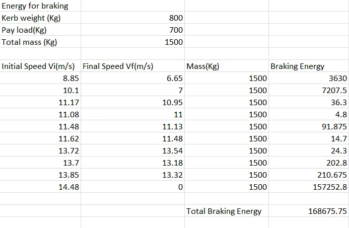
From the drive cycle we can see 10 braking points and from the graph we can see the time taken is 137 sec and the speed in m/s.
Therefore the total energy for braking is 168675.75 watts.
In the excel sheet graph of braking we can see below
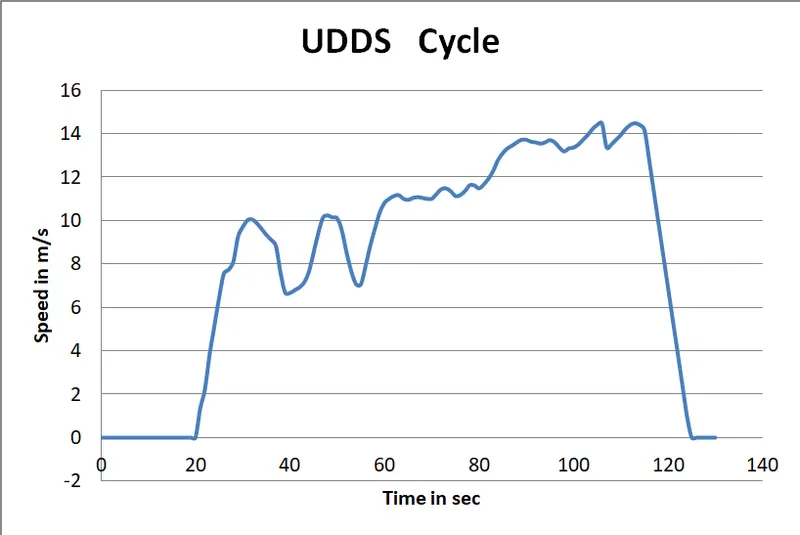
Conclusion:
We saw the drive cycle of UDDS cycle for braking energy.
2.Why electric motor can’t develop braking torque at high speed similar to starting? How electric and mechanical brakes are coordinated?
An AC induction motor is supposed to be a constant power motor, which implies it draws more current on low voltage. Consider a motor running a constant torque load at a particular speed. Suppose now the voltage is reduced, which should cause it to settle down at a lower speed supplying the same torque as per the new torque speed characteristic. If we consider the electrical side, higher slip will cause more current to be drawn that too at higher pf, which should maintain the power justifying the above theory. But on the mechanical side the new output power Torque x speed is supposed to be lesser now as speed is less now.
We have three types of loads:
Constant Torque load:
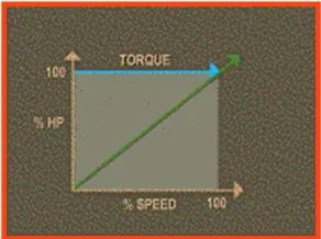
Constant torque loads require the same amount of torque at low speeds as at high speeds. Torque remains constant throughout the speed range, and the horsepower increases and decreases in direct proportion to the speed. Constant torque loads include most positive displacement and reciprocating pumps and compressors as well as traction drives and conveyors. With constant torque loads, the torque is not a function of speed. As speed is changed, the load torque will remain fairly constant and the horsepower will change linearly with the speed.
For example, if the speed increases by 50%, then the power required to drive the operation will increase 50% while the torque remains constant.
Constant Power load:
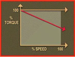
Constant horsepower loads require high torque at low speeds and low torque at high speeds, which means constant horsepower at any speed. Constant horsepower loads include grinders, winding machines and lathes. For constant horsepower loads, the torque loading is a function of speed up to 100% operating speed. As the speed of the operation is decreased, the torque increases so that the horsepower required remains essentially constant.
Variable Torque loads:
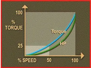
Variable torque loads require much lower torque at low speeds than at high speeds. The torque required varies as the square of the speed and the horsepower required varies as the cube of the speed. Variable torque loads include most centrifugal and axial pumps, fans and blowers and many mixers and agitators.
As the speed is decreased, the torque will decrease by the square of the speed decrease and the horsepower required decreases by the cube of the speed decrease.
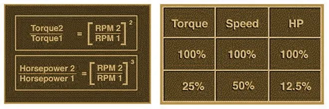
As an example, when the speed of a variable torque load is reduced by 50% or one half, the torque required to drive the load is reduced to one-quarter or 25%. The horsepower is reduced to the speed cubed, which is 1/8, or 12.5% of that required to drive the load at full speed.
So from all these different loads we caame to know that when the motor is at rest and it has to operate from stand still position to reach the moderate speed the high torque is required to bring the motor in operation.When the vehicle is already at high speed the capping or the limits is reached by the motor operation and thus any further higher torque could not be provided while braking.The braking operation happens in the motor which is been disturbed as per the proportion in the Brake Energy and Regenerative Braking.
Braking systems:
Braking systems are necessary for the correct and safe operation of mechatronicsystems. Most functional braking is achieved using electrical braking, which is madepossible by the addition of a variable speed drive system (e.g., variable frequency
drive system). Electrical braking is efficient and ensures smooth operation andallows the designer to recover the mechanical energy. However electrical brakingcannot be used as a safety braking system for the cases of emergency braking and
parking braking. It is for these reasons that mechanical braking systems are stillemployed today, in order to act as emergency and parking brakes.
The Rationale for Braking Systems
In any motion control system, braking is necessary for the following reasons:
1. In order to ensure that the system follows the correct speed time profile.
2. In order to stop the system in cases of emergency.
3. In order to ensure that the system remains stationary when not in operation.
Two types of braking systems are employed in most drive systems: electrical andmechanical. In this note a general overview is presented of the two types of brakingsystems, and it concludes with a comparison of the two types.
Types of Electrical Braking Systems
There are six methods of electrical braking in drive systems, listed below:
1. Plugging: The three phase voltage sequence is reversed at the statorterminals of the induction motor. The equivalent form of plugging in dc drivesystems is the reversal of the polarity of the armature voltage of a dc motor.
2. DC Injection Braking: A d.c. voltage is applied to any two of the three
terminals of the induction motor.
3. Eddy Current Braking: A separate eddy current braking device is coupled tothe shaft of the motor. Eddy current braking results when electromagnets areactivated and they induce eddy currents in the rotating metallic disk. The eddycurrents produce magnetic fluxes that oppose the flux produced by theelectromagnets and thus result in a braking torque on the motor. The energy is dissipated as heat in the rotating metallic disk.
4. Dynamic Resistor Braking: In variable frequency drive systems, when themotor is braking and acting as an induction generator, it returns power back tothe d.c. link capacitor and the voltage of the d.c. link increases. A resistor canthus be used to dissipate the excessive charge on the capacitor, whereby anIGBT is controlled to proportionately switch the resistor in parallel with the capacitor (using pulse width modulation switching). The excessive energy isthus dissipated in the resistor.
5. Regenerative Braking: Rather than dissipating the excessive charge in the resistor, it is possible to return the excessive energy back to the three phasesupply by using a dedicated inverter, placed in parallel with the uncontrolled
rectifier that is used in the variable frequency drive system.
6. Sharing the DC Bus: Another possible method of removing the excessive charge on the capacitor is to share the d.c. between a number of different variable frequency drive systems. The drive that is braking can supply energyto the drive that is motoring. In such a case, there is no need to dissipate the excessive energy into a resistor or to return it to the three phase power source.In the first two methods, the excessive energy is dissipated as heat in the motoritself. In the Eddy current method, the excessive energy is dissipated as heat in thenmetallic disk. In the fourth method, the excessive energy is dissipated as heat in the resistor. In the fifth method the energy is returned to the ac suppy. In the sixthmethod, the energy circulates between the different motors (from the one that is acting as a generator to the one that is acting as a motor).
In cases where it is possible to recover the energy, the following can be done:
1. It can be stored in batteries.
2. It can be stored in a flywheel (a flywheel that has an integrated permanent
magnet dc alternator).
3. It can be returned to the ac supply using a regenerative drive.
Mechanical Braking Systems.
There are four types of mechanical brakes used in drive systems:
1. Drum brakes.
2. Disk brakes.
3. Band brakes.
4. Pawl and Ratchet brakes: The ratchet is linked to a spring loaded frictionplate. The ratchet is lifted using a solenoid.The drum and disk brakes are either electromagnetically lifted or hydraulically lifted,but always spring applied. They must be spring applied for safety reasons, so thatwhen the power supply is lost, the brake will apply and safely bring the load to a standstill.
Comparison between Electrical and Mechanical Braking Systems:
The following is a comparison between electrical and mechanical braking systems:
a. Electrical braking systems are used for functional braking (controlling thespeed; bringing the load to standstill). Mechanical braking systems are usedfor emergency stopping or for parking.
b. Electrical braking is usually very smooth and comfortable. Mechanical brakingis usually rough and uncomfortable.
c. No wear results from electrical braking. Mechanical braking on the other handcauses wear in the braking components and requires regular maintenance.
d. It is possible (but not always feasible) in electrical braking systems to returnthe regenerated energy back to main supply. This is not possible inmechanical braking systems and the energy is always lost as heat, noise andwear.
e. The electrical braking system cannot be used as a safety device. Most
systems will require a mechanical braking system as backup safety device.
Conclusion:
Since we discussed the co_ordination of electrical and mechanical brakings.
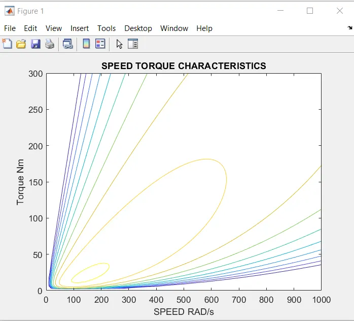
3.Make a MATLAB program which plots contour of given motor speed, torque and efficiency values. Attach the code as a .m file attach a screenshot of all the plots.
A contour is a graphical technique of representing a 3Dimensional surface.It represents the height in 2D surface.
Matlab code:

Output graph:
Conclusion:
From the graph we can see the inner contour has higher efficiency than the outer contour.