Week-11 Challenge: Braking
Aim: The following challenge has 3 exercises:
- For a defined driving cycle, calculate the energy required for braking.
- Why electric motor can’t develop braking torque at high speed similar to starting? How electric and mechanical brakes are coordinated?
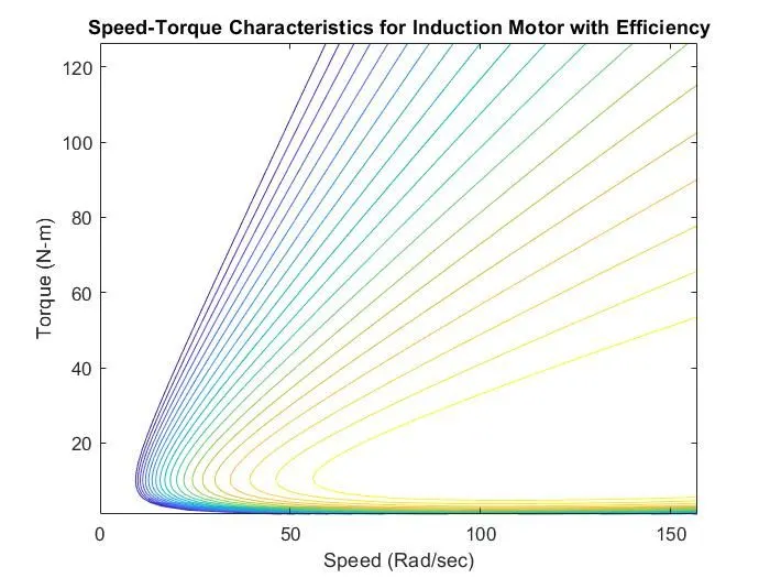
- Make a MATLAB program which plots contour of given motor speed, torque and efficiency values. Attach the code as a .m file attach a screenshot of all the plots.
Software Used: MATLAB R2021a, Simulink, MS Word.
Solution:
For a defined driving cycle, calculate the energy required for braking.
The energy required for braking can be calculated using the formula below:
As the vehicle decelerates during braking,
Braking Energy (B.E.) = ½*Mass of Vehicle(m)*(Vi – Vf)2,
Where,
Vi = Initial Velocity,
Vf = Final Velocity,
The following Simulink Model calculates the braking energy for the drive cycle FTP75 (2474 seconds) for every second:
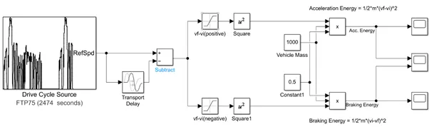
To identify whether the vehicle is accelerating or decelerating, a transport delay block is used subtract the speed value at t second to the speed value at t-1 second. If the result is positive, the vehicle is accelerating and if the result is negative, the vehicle is decelerating i.e., the vehicle is under braking action.
Braking Energy plot:
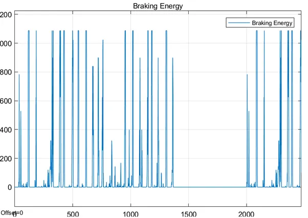
X-axis = Time (in seconds),
Y-axis = Energy (in Joules) (from 0 – 1200),
Why electric motor can’t develop braking torque at high speed similar to starting? How electric and mechanical brakes are coordinated?
According to the Speed – Torque characteristics of DC motor, at maximum speed there is no torque applied to the motor. When the motor starts, we get the maximum torque in the Speed – Torque characteristics and it is utilised for the vehicle to accelerated, at maximum speed, no torque is applied which can be converted in braking torque.
Due to this, electric motor can’t develop braking torque at high speed similar to starting.
Electrical and Mechanical brakes are co-ordinated by using two methods:
Series Braking: It is applied when the electric and mechanical brakes are applied after each other.
Parallel Braking: It is applied when both electric and mechanical brakes are applied together.
Make a MATLAB program which plots contour of given motor speed, torque and efficiency values. Attach the code as a .m file attach a screenshot of all the plots.
The following MATLAB script takes voltage value as user input and frequency of 50 Hz is applied and calculates Motor Speed, Torque, Power and Efficiency.
It also considers motor power losses like Copper loss, Iron Loss, Windage Loss and Constant Losses.
clear all
close all
clc

%voltage input
V = input('Enter Voltage (V) = ');

%Motor parameters
R1 = 0.095;
R2 = 0.23;
X1 = 0.68;
X2 = 0.672;

%no. of poles
p=4;

%Frequencies
f = 50;

%loop for calculating speed
for j = 1:length(f)
Wms = 120*f(j)/p;
Wrms = Wms*2*pi/60;

%slip
s = linspace(0,1,Wms);

%loop for calculating torque
for i = 1:Wms
Wm(i,j)=(1-s(i))*(Wms);
a(i,j) = 3./Wrms;
b(i,j) = ((V^2)/3)*(R2./s(i));
c(i,j) = ((R1+(R2./s(i)))^2)+((X1+X2)^2);
T(i,j) = a(i,j)*b(i,j)./c(i,j);

end
end

WRMS = linspace(Wrms,0,Wrms);%speed in radians
[X,Y] = meshgrid(WRMS,T);

%loss constants
kc = 0.2;%copper losses
ki = 0.008;%iron losses
kw = 0.00001;%%windage losses
constantL = 20;%constant motor losses

Po = X.*Y;%output power
B = kc.*(Y.^2);%copper loss
C = ki.*X;%iron loss
D = kw.*(X.^3);%windage loss

Pi = Po + B + C + D + constantL;%input power
n = Po./Pi;
Eff = linspace(0.7,0.93,20);%efficiencies

%plotting
figure(1)
box off
contour(X,Y,n,Eff)
xlabel("Speed (Rad/sec)")
ylabel("Torque (N-m)")
title("Speed-Torque Characteristics for Induction Motor with Efficiency");
Results: