Week-11 Challenge: Braking
Solution 1.:- For a defined driving cycle, calculate the energy required for braking.
Driving Cycle: A driving cycle are a set of vehicle speed points versus time, it is used to calculate the fuel consumption of a vehicle, which is later on is compared with different vehicles. Main use of driving cycle are as follows:
- To assess the performance of a vehicle (fuel economy, emission tests)
- To analyze battery state and energy consumption in Electric Vehicles
- To simulate vehicle model prior to the actual development
Braking: Road vehicles involves the conversion of kinetic energy into thermal energy (heat). When stepping on the brakes, the driver commands a stopping force several times as powerful as the force that puts the car in motion and dissipates the associated kinetic energy as heat.
The process of braking follows the law of conservation of energy i.e. Energy cannot be created or destroyed it can only be converted into another form.
E(kinectic) = 1/2*m*v^2...
where,
m = mass of the vehicle in Kg
v = velocity of the vehicle in m/s
E(kinectic) = Kinectic energy in KJ
In our case, velocity will be (V-Vi) where, V is the speed of the vehicle, Vi the speed of the vehicle which is slow down or brought down to rest.
Matlab Code for calculating Energy required for Braking
clear all
close all
clc
%Read the Drive Cycle data from given .xls file
DC=xlsread('VelocityandTime.xlsx');
T=DC(:,1); %Time in seconds
S=DC(:,2); %Speed in Kmph
%other data
m = 1000; %mass in Kg
V=S./3.6; %Speed in m/s
%To create an Array to store values for Deceleration & Braking Energy
Z=length(T);
deceleration=zeros(1,Z);
acceleration=zeros(1,Z);
BE=zeros(1,Z);
AE=zeros(1,Z);
for i=1:(length(T)-1)
if V(i)>V(i+1)
BE(i)=0.5*(V(i)-V(i+1))^2; %Braking Energy in Joules
speed_decrease(i)=V(i+1)-V(i);
deceleration(i)=speed_decrease(i);
%since Time Delta is 1s Acc/dec=V/T..m/s^2, where T=1
end
if V(i)<V(i+1)
AE(i)=0.5*m*(V(i)-V(i+1))^2; %Accelerating Energy in Joules
speed_increase(i)=V(i+1)-V(i);
acceleration(i)=speed_increase(i);
end
end
%Total Braking Energy in KJ
B_E=(sum(BE)/1000);
%Total Acceleration Energy in KJ
A_E=(sum(AE)/1000);
%Plotting Curves
figure(1)
subplot(2,1,1)
plot(T,S,'color','b')
xlabel('Time(s)')
ylabel('Speed(Kmph)')
title('Drive Cycle')
subplot(2,1,2)
plot(T,deceleration,'color','r')
hold on
plot(T,acceleration,'color','g')
xlabel('Time(s)')
ylabel('Acc/Dec(m/s^2)')
title('Acceleration-Deceleration')
figure(2)
plot(T,BE)
hold on
plot(T,AE)
xlabel('Time(s)')
ylabel('Energy(J)')
title('Energy consumed during Braking & required for acelerating throughout Drive Cycle')
legend('Braking Energy','Accelerating Energy')
fprintf('Total Energy consumed during Braking is %f KJ',B_E)
disp(' ')
fprintf('Total Energy consumed during Acceleration is %f KJ',A_E)
For Driving cycle an Excel sheet is imported,
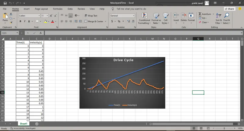
Code Explanation:
-- An excel sheet name 'VelocityandTime'.xls is been imported into matlab workspace and the Time and Velocity values are inserted into Arrary
-- All the values like mass, velocity are been defined first in the code, Velocity value is converted into m/s.
-- A for loop for the length of time value is been created.The variable name length has been defined.
-- Acceleration and Deceleration values are been calculated inside a for loop.
-- Total energy is calculated.
-- All the required input has been mentioned for plotting graphs.
Results:
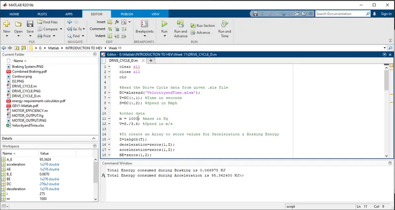
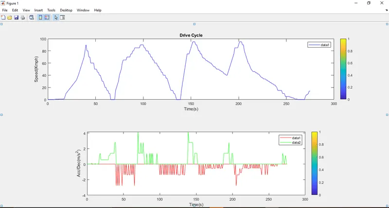
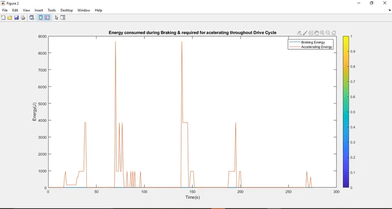
-- We can observe after the simulation is completed the two values Total energy required in braking 0.066975 KJ whereas, Total Energy consumed during Acceleration is 95.342400 KJ.
-- We can also observe the driving cycle is same as the excel file which was imported.
-- We can also observe the Energy consumed during braking as well as while accelerating red color is for Acceleration whereas, the blue color is for braking
Solution 2. :- Why electric motor can’t develop braking torque at high speed similar to starting? How electric and mechanical brakes are coordinated?
Regenerative Braking:
This are the type kinectic energy recovery system that transfer the kinectic energy of an object into potential or stored energy to slow down the vehicle and as a result to increase the fuel efficiency.There are multiple methods of energy conversion in Regenerative Braking System including spring, flywheel, electromagnetic and hydraulic. More recently, an electromagnetic-flywheel hybrid.
They are are installed along the drive train or fitted to the drive wheels of a vehicle where they inhibit the motion of the wheels using magnetic fields or mechanical torque. These methods of motion inhibition allow energy to be generated under braking, as opposed to friction brakes which simply waste away energy to slow the vehicle by turning the kinetic energy into thermal energy.
Regenerative Braking system can improve fuel consumption and reduce the overall braking load taken on by the vehicles friction brakes, reducing the wear on the brake pads. In HEV and EV the transmission of the car is set up such that when the driver applies the brakes, the electric motor reverses itself and applies a resistance to the wheels rather than power, this resistance applied to the wheels is then put through the electric motor where it is used to recharge the batteries.
Limitations :
There is a limitation due to the maximum recharging rate of the circuit and the capacity of battery, the braking force from an electromagnetic is always limited.
Why electric motor can’t develop braking torque at high speed similar to starting?
In EV application there is a motor-generator, and a battery pack to supply power, as the electric current travels through the motor within a magnetic field, it generates a force. The more current applied, the more the motor will spin.
For Regenerative Braking a motor will act as a generator i.e. the direction of the electric flow is reversed, the electric motor will rather than taking in current to spin the armature, the armature is spun through the field by the deceleration of the vehicle. The electricity produces is used to recharge the battery, and the motor can switch between powering the car and regenerating electricity as fast as the driver can accelerate and lift off.
As the motor revsere increase, it also creates "back electromotive force" or "back EMF." The faster the motor spins, the more back EMF is created, reducing the effective voltage it can deliver. But at zero RPM, all of the electricity the motor creates from the time electric power is applied becomes instant torque—without any back EMF to reduce its output. The higher the revs, the more back EMF, meaning that instantaneous torque effect diminishes.
The reason behind this no matter how much the current loop wants to increase current (proportional to torque) by increasing the PWM duty cycle of the power stage, the Vmotor is too close to Vbemf and therefore current can't increase more.
-- Whenever Friction torque + Additional loads = Motor Torque, the load remain in equilibrium(moves under a constant speed)
-- Whenever Friction torque + Additional loads < Motor Torque, the load accelerates (Motor torque - Friction torque - Additional loads = Acceleration torque > 0).
-- But, at high speed the BEMF is so close to Vbus that the applicable Motor torque gets limited, the bigger the Friction torque + Additional load is, the smaller the Acceleration torque becomes.
-- This situation does not occur at the beginning of an acceleration because most of the torque is used to increase the kinetical energy of the load (and motor). But when the speed is already high and no extra load is applied it is not possible to increase the torque.
We can prevent this by,
-- Increase DC bus voltage.
-- Unlimit system acceleration.
-- Use a motor with less resistance and lower back EMF proportion.
How electric and mechanical brakes are coordinated?
A Regenerative Braking system is used to convert waste energy(heat) into useful energy(stored in battery) with the help of a motor which acts as a generator when reversed. There are certain limitation with RBS i.e. the electric motor is unable to provide all the brake torque necessary for large decelerations. In case of braking if the braking torque is applied only one axle, there are chances stability and maneuverability issues can occur. So to avoid such situation regenerative braking is operated in conjunction with a friction(mechanical) brake system.
The RBS and Mechanical Brake sytem are used in strategic manner which is called as Brake Control Strategy
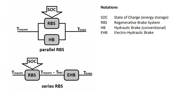
1. Series Brake Control or Series RBS:
In this type of control system the Mechanical Brakes and Regenerative(Electric) Brakes are applied one after the another. We can only apply one brake system at a time either RBS or Mechanical brakes.
The series brake system is further classified:
a. Comfort of the drive
b. Braking according to the energy efficiency
2. Parallel Brake Control or Parallel RBS:
In this type of brake control system both the Mechanical Brakes and RBS are applied simultaneously.
Solution 3.:- Make a MATLAB program which plots contour of given motor speed, torque and efficiency values. Attach the code as a .m file attach a screenshot of all the plots.
Losses that occur in all types of Electric Motor:
1. Copper Loss: I^2.R, where R is the Armature resistance and we can say that Torque is proportional to Current, this copper loss can be consider as Kc.T^2, where Kc is the resistance of brushes and the flux and its effect.
Copper Losses = Kc.T^2
2. Iron Losses: Iron losses are occured due to Magnetic losses and it is denoted as Ki.ω, where Ki is the factor which is based on the Magnetic field effect. For Permanent Magnets which has constant Magnetic field and this iron losses are based on the value of Ki and this keeps on changing due to variation in speed.
Iron Losses = Ki.ω
3. Windage Losses: This are based on the size & shape of the Motor and the amount of windage losses that the motor is going to experience.
Windage Losses = Kw.ω^3
4. Constant Losses: This losses are present in the motor constantly and are denoted by C.
Total Losses: The Total Losses are consider by combining all the four losses and denoted as,
Total Losses = Kc.T^2 + Ki.ω + Kw.ω^3 + C
Matlab Code for Motor Efficiency
%Efficiency Mapping for Electric Motors
clear all
close all
clc
x = linspace(1,1000); % Speed in rad/s
y = linspace(1,250); % Torque in Nm
%Motor loss constants
Kc = 0.2; %Copper Loss
Ki = 0.008; %Iron Loss
Kw = 0.00001; %Winding Losses
C = 20; %Constant Motor Losses
[X,Y] = meshgrid(x,y);
Output_Power = (X.*Y);
- C_1 = (Y.^2)*Kc; %Copper Loss
I_1 = (X*Ki); %Iron Loss
W_1 = (X.^3)*Kw; %Winding Loss
Input_Power = Output_Power+C_1+I_1+W_1+C;
Z = Output_Power./Input_Power;
V = [0.70,0.80,0.85,0.90,0.91,0.92,0.925,0.93];
box off
grid off
[c,h] = contour(X,Y,Z,V);
xlabel('Speed(rad/s)');
ylabel('Torque(N/m)');
clabel(c,h);
Code Explanation
-- All the values of Speed and Torque are inserted using linspace command in the form of array.
-- A 2D grid of the arrays are created using meshgrid command.
-- Various Motor losses and their coefficient are defined and stored.
-- Motor Losses are calculated:
- Copper Losses = Kc.T^2
- Iron Losses = Ki.W
- Windage Losses = Kw.W^3
-- Input and Output Power are calculated.
-- A contour is plot for the Torque Speed curves, efficiency is mapped using clabel command.
Results
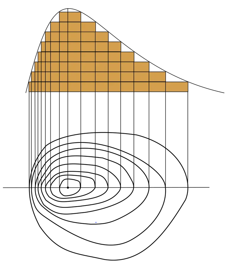
Contour Plot: Contour plots is the way to show a three-dimensional(3-D) surface in the two-dimensional(2-D) plane. It graphs two predictor variables X Y on the y-axis and a response variable Z as contours.
In our simulation we can observe the X-axis as the Speed(rad/s) and Y-axis as the Torque(N-m).
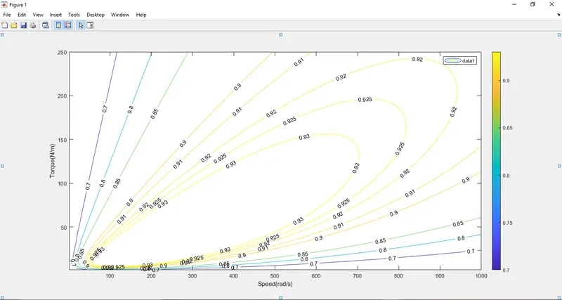
-- We can observe in the output results efficiency plotting for various efficiency values which where mentioned in the matlab code.