Week-6 Challenge: EV Drivetrain
Solution 1 :- Which types of power converter circuits are employed in electric and hybrid electric vehicle?
Hybrid Vehicle : A hybrid vehicle is one that uses two or more distinct types of power, such as submarines that use diesel when surfaced and batteries when submerged. The basic principle with hybrid vehicles is that the different motors work better at different speeds; the electric motor is more efficient at producing torque, or turning power, and the combustion engine is better for maintaining high speed (better than a typical electric motor). Switching from one to the other at the proper time while speeding up yields a win-win in terms of energy efficiency, as such that translates into greater fuel efficiency.
Hybrid electric vehicles are powered by an internal combustion engine and an electric motor, which uses energy stored in batteries. A hybrid electric vehicle cannot be plugged in to charge the battery. Instead, the battery is charged through regenerative braking and by the internal combustion engine
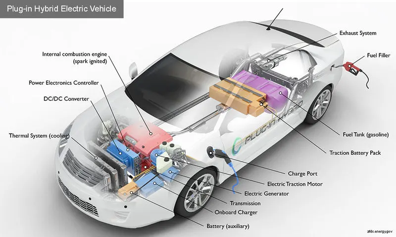
Electric Vehicle : An electric vehicle (EV) is a vehicle that uses one or more electric motors or traction motors for propulsion. An electric vehicle may be powered through a collector system by electricity from off-vehicle sources, or may be self-contained with a battery, solar panels, fuel cell or an electric generator to convert fuel to electricity. EVs include, but are not limited to, road and rail vehicles, surface and underwater vessels, electric aircraft and electric spacecraft.
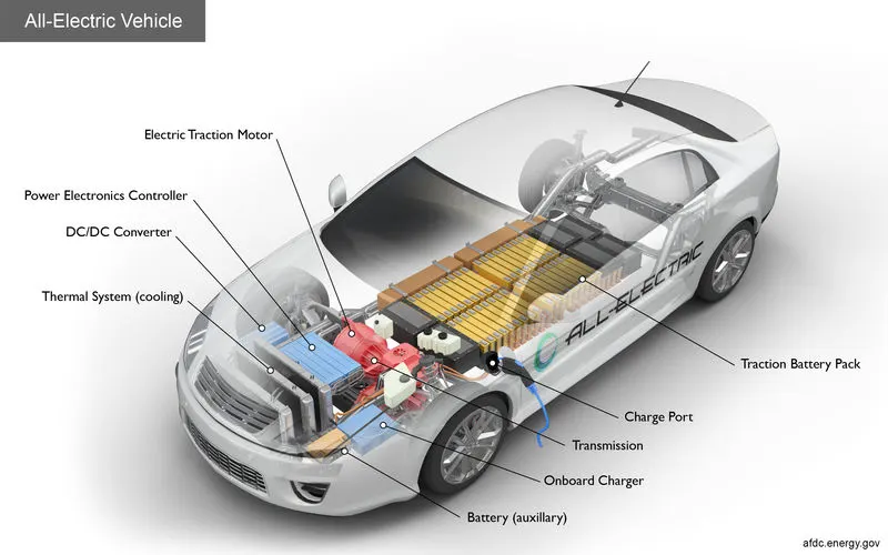
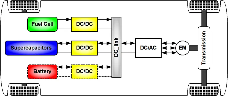
- As, we can now understand that which ever case may be Hybrid or All-Electric Vehicle we require two or more power source generation component to run the vehicle efficiently and smoothly. The main challenge which is faced while design these vehicle is the voltage and current regulations according to the demand of vehicle while running, so to maintain this voltage and current regulation we install different types of Power electronics devices namely the Power converter.
Power Electronics : Power Electronics refers to an interdisciplinary subject within electrical engineering that deals with the design, control and conversion of power in its electric form. A system that converts electric energy to an electric load through a control circuit is known as a Power Electronic System
- Power electronics is in the early stages of significant technological opportunities which will greatly enhance the role and value of electricity in all aspects from generation to the end of use. Power electronics represents an enabling means in enhancing the role and value of electricity. The basic functions of importance for power electronics are (1) power conversion, ac to dc, dc to ac, ac to ac, (2) power conditioning to remove distortion, harmonics, voltage dips and overvoltages, (3) high speed and/or frequent control of electrical parameters such as currents, voltage impedance, and phase angle, and (4) high speed and/or frequent circuit interruption transfer, and current limiting functions.
Power Converter used in HEV/EV :
1. DC-DC converter : This type of converter is used where we have to step-up or step down the voltage in the circuit without changing its wavefrom.
A bi-directional DC-DC converter is used in HEV/EV for regenerative braking system.
DC-DC converter are further classified according to the use in HEV/EV
1.1 NON-ISOLATED CONVERTER : This type of converter is used where the voltage needs to be step up or step down in a small ratio(less than 4:1) and where there is no issue of input and output no dielectric isolation. There are five types of non-isolation converter
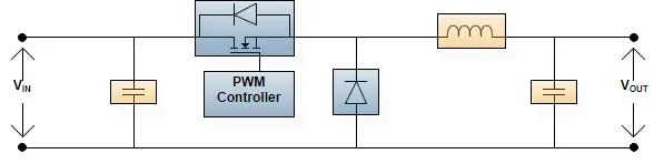
a. Buck DC-DC Converter
- The buck converter is a very simple type of DC-DC converter that produces an output voltage that is less than its input. The buck converter is so named because the inductor always “bucks” or acts against the input voltage. The output voltage of an ideal buck converter is equal to the product of the switching duty cycle and the supply voltage.
- Like many power supply topologies, the buck converter operates on the principal of storing energy in an inductor. The voltage drop across an inductor is proportional to changes in electric current flowing through the device.
- The switching element, often a power MOSFET or IGBT, is ideally either opened or closed – off or on – so the buck converter circuit will alternate between two different states.
- The buck converter works similar to the SMPS used in different apllications.
b. Boost DC-DC Converter
- The Boost converter is used where the voltage needs to be step-up according to the requirement.
- The key principle that drives the boost converter is the tendency of an inductor to resist changes in current by either increasing or decreasing the energy stored in the inductor magnetic field.
- In a boost converter, the output voltage is always higher than the input voltage.
- The boost converter is used in the battery power system where to reduce number of cells and increase the voltage to meet the requirement.

c. Buck-Boost DC-DC Converter
- The Buck-Boost converter is used where the input voltage is either step up or step down according to the requirement.
- This stepping up & stepping down is operated by a siingle inductor.
- Two different topologies are called buck–boost converter. Both of them can produce a range of output voltages, ranging from much larger (in absolute magnitude) than the input voltage, down to almost zero.

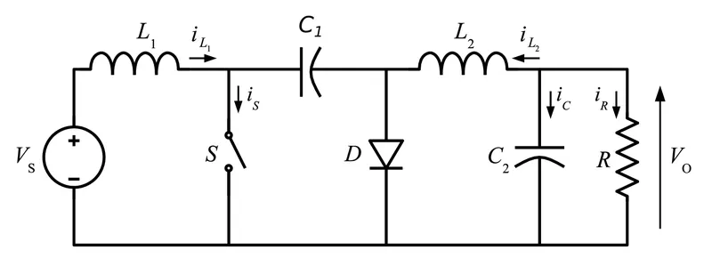
d. Cuk DC-DC Converter
- The operation of Cuk Converter is similar to the Buck-Boost converter but with zero ripple current.
- The inductor plays a vital role in the DC-DC converter for switching the output to high or low voltage, a capacitor is used to store the energy.
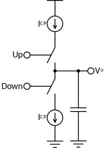
e. Charge PUMP DC-DC Converter
- This type of converter is used where the efficiency required is high enough upto 90-95%. The input voltage in the circuit gives the output voltage all most double thus increasing the efficiency of the circuit.
- A charge pump is a kind of DC-to-DC Converter that uses capacitors for energetic charge storage to raise or lower voltage. Charge-pump circuits are capable of high efficiences, sometimes as high as 90–95%, while being electrically simple circuits.
1.2 ISOLATION CONVERTER :
- This type of converters a high frequency transformer is used. In the applications where the output needs to be completely isolated from the input, an isolated converter is necessary.
- Isolation describes the electrical separation between the input and output of a dc-dc converter. An isolated dc-dc converter uses a transformer to eliminate the dc path between its input and output.
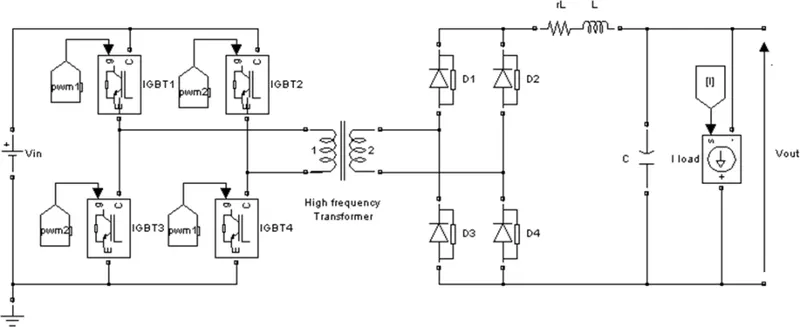
a.Full Wave Bridge DC-DC Converter
- A full-bridge DC/DC converter is the most frequently implemented circuit configuration for fuel-cell power conditioning when electrical isolation is required.
- The full bridge DC/DC converter is suitable for high-power transmission because switch voltage and current are not high.
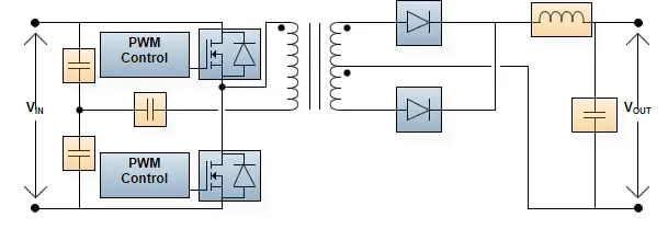
b. Half Wave Bridge DC-DC Converter
- A half-bridge converter is a type of DC-DC converter that, like flyback and forward converters, can supply an output voltage either higher or lower than the input voltage and provide electrical isolation via a transformer.
c. Flyback DC-DC Converter
- The flyback converter uses a single magnetic, although commonly referred to as a transformer actually behaves as a coupled inductor. This transformer combines the functions of energy storage, energy transfer, and isolation, so the need for a separate LC filter on each output is eliminated.
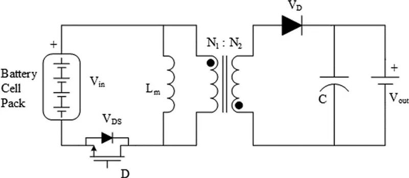
d. Push-Pull DC-DC Converter
- A push–pull converter is a type of DC-DC converter, a switching converter that uses a transformer to change the voltage of a DC power supply. The distinguishing feature of a push-pull converter is that the transformer primary is supplied with current from the input line by pairs of transistors in a symmetrical push pull circuit.
- The transistors are alternately switched on and off, periodically reversing the current in the transformer. Therefore, current is drawn from the line during both halves of the switching cycle.
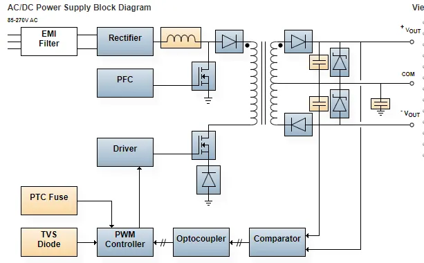
2. AC to DC Converter :
- AC/DC power supplies are straightforward - connect the input to an AC power source, which can be high voltage mains or a wall outlet.
- The power supply then converts the AC power into DC power. When selecting an AC to DC power supply, it’s important to determine the output power and voltage required for the system so the correct power supply can be used.
- AC-DC converter is also used in EV with AC Induction motors.
Solution 2:- An Electric Vehicle's powertrain with 72V battery pack in shown in the diagram below. The duty ratio for acceleration operation is 'd1' and for the braking operation the duty ratio is 'd2'.
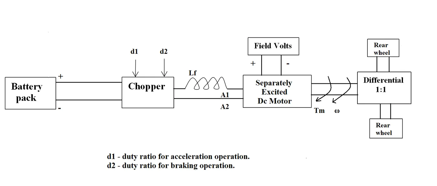
The other parameters of the electric vehicle is given below,
Motor and Controller Parameters:
Rated Armature voltage= 72 V
Rated armature current= 400 A
Ra= 0.5Ω, KΦ= 0.7 Volt second
Chopper Switching frequency= 400 Hz
The vehicle speed-torque characteristics are given by the below equation

What is EV steady state speed if duty cycle is 70%?
Given Data :
- Battery Pack / Rated Armature Voltage = 72V
- Rated Armature Current = 400A
- Armature Resistance(Ra) = 0.5ohms
- Motor Constat(K) = 0.7Volt second
- Chopper Switching Frequency = 400Hz
- Duty Cycle = 70%
- Output Voltage = Battery Voltage * Duty Cycle; = 72 * 0.70 = 50.4V
- T = 24.7 + (0.0051)*w^2---------Equation(1)
- Motor Torque Equation,
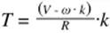 or T = (V*k/Ra) - ((K)^2/Ra)*w
= (50.4*0.7/0.5) - (0.7^2/0.5)*w
T = 70.56 - 0.98*w--------Equation(2)
Substituting the equation(1)&(2)
24.7 + 0.0051*w^2 = 70.56 - 0.98*w
0.0051*w^2 + 0.98*w - 45.86 = 0
Solving by Quadratic Equation we get,
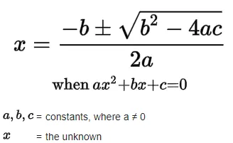
w = 38.915 rad / sec or w = -231.072 rad / sec
Taking the positive value,
w = 38.915 rad / sec or w = 372 RPM--(1rad/sec = 9.5493 RPM)
So, the steady state speed of the EV while the duty cycle @ 70% w = 38.915rad/sec or w = 372RPM
Solution : - 3. Develop a mathematical model of a DC Motor for the below equation using Simulink.
ω">ωω= V/Kϕ">ϕϕ -Ra/Kϕ">ϕϕ^2 .T
Given Data :
---- w = V/K - R/K^2*T
- Simulink Model :
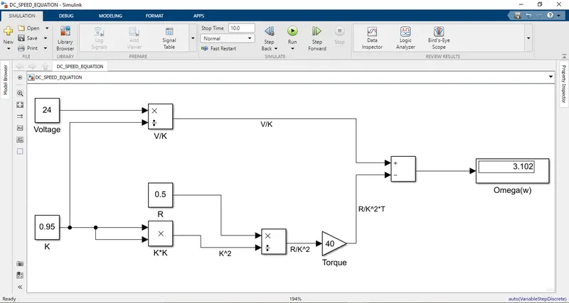
- To model, the equation we need to open the Simulink window from Matlab i.e. Matlab>>Simulink>>Create Model.
- We will require Constant blocks to assign values for V,K,R we are assuming the value to be constant throughout the simulation.
- To form the value V/K we will require a Divide block which is inupted from the library browser>>Mathematical Operations.
- To form the value R/K^2 we will require two blocks Divide and Product blocks, a Product block is used to get the value K^2.
- We also need to add the Torque value which is been multiplied with the value R/K^2 for that we have added a Gain block from the library browser.
- After the two values are formed then they are outputed with the help of Add block which is then further connected with the Display block for the Omega(w) value.
- After, properely connecting the respective blocks to each other, we have simulated the model.
- We have assumed the values, V=24; K=0.95; R=0.5; T=40
- After running the simulation for 10 seconds we get the value of Omega(w) as '3.102' as shown in the Display block.
- To valdiate our simulation result, we can manually calculate the value by substituting the values in the above given equation.
- w = (24/0.95) - (0.5/0.95^2)*40 = 3.102
- Hence, we can observe that both values are same, so our mathematical model is correct.
- Refer to the blog on below topic:
Induction Versus DC brushless motors by Wally Rippel, Tesla
Explain in brief about author’s perspective.
Author Mr. Wally Rippel explains,
- He is a engineer by his profession who has worked for different companies like AeroVironment, Jet Propulsion Laboratory before joining Tesla Motors, he has also built an electric vehicle(converted Volkswagen microbus) for which he has won the Great Transcontinental Electric Car Race against MIT.
- After, this he discusses about the IC Engine Vehicles and the type of Engines which are used as per the requirement of the models, and the same goes with Electric Vehicle also which requries Electric Motor for power source.
- He explains about the evolution which has happened in the Battery Technology i.e. lead acid replaced by lithium same goes with motor as well i.e. DC Motor replaced by Brushless DC Motor or Induction Motor.
- He explains the difference between a Brushless DC Motor and Induction Motor, the Brushless DC motor two or more permanent magnets which generates DC magnetic fields, this magnetic field enters the stator core which in turns interacts with currents flowing within the windings to produce a torque interaction between the rotor and stator.
- As the rotor rotates, it is necessary that the magnitude and polarity of the stator currents be continuously varied – and in just the right way - such that the torque remains constant and the conversion of electrical to mechanical energy is optimally efficient. The device that provides this current control is called an inverter. Without it, brushless motors are useless motors.
- Now he explains about the 3-Phase AC Induction motor, the construction of the stator of both motor is very identical/similar to each other, the main difference is in the construction of the rotors. The brushless DC motor has two or more magnets in the rotor whereas, the AC induction motor does not have any magnets in the rotor instead it has stacked steel laminations with buried peripheral conductors that form a “shorted structure".
- After, this the current flowing in the stator produces rotating magnetic field which then enters the rotor of the motor, due to this an induced voltage is generated which is proportionate to this speed difference between the rotor and electrical frequency. After, this voltage, currents are produced within the rotor conductors that are approximately proportionate to the voltage, hence the speed difference and hence finally, these currents interact with the original magnetic field to produce forces – a component of which is the desired rotor torque.
- Now, he explains about the advantage of 3-Phase Induction motor this type does not require a inverter i.e. the torque is produced at offset hence it starts under load, whereas in the Brushless DC motor requries an inverter to start under the load. The AC induction motor is not operatble in DC mode, it can be only operated in AC mode, thus an inverter is required, but then to it won't match the performance of Brushless DC motor, unless a proper feedback loop is not provided to operate at certain frequency to match the performance of Brushless DC motor.
- Brushless DC motor are mostly used in Hybrid & Plug-In vehicle, whereas the AC Induction motor is used in General Motors EV-1, the Air Proplusion and in Tesla Roadster. Both DC brushless and induction drives use motors having similar stators. Both drives use 3-phase modulating inverters. The only differences are the rotors and the inverter controls. And with digital controllers, the only control differences are with control code.
- The Brushless DC motor produces very less amount of heat therefore, the cooling system is easier and the peak efficiency is much higher all most near to the unity power, whereas the Induction motor is upto 85 percent. In A Brushless DC motor the magnetic field produced by magnet is adjustable, so when the speed is low the torque is high whereas when the speed is high the torque requiredis low,when torque levels are low, the B field should be reduced such that eddy and hystersis losses due to B are also reduced. Ideally, B should be adjusted such that the sum of the eddy, hysteresis, and I² losses is minimized.
- In the AC induction motor does not have any magnets so the losses are very less, as the size of Brushless DC motor grows the losses also becomes high whereas this is not the case in AC Induction motor so where the high performance is needed the use AC Induction motor is favourable. Permanent magnets are expensive so the Brushless DC motor are not favourable whereas, the induction motor requries a low cost inverter and produces very low voltage when de-exited so easy to protect.
- Induction machines are more difficult to control. The control laws are more complex and difficult to understand. Achieving stability over the entire torque-speed range and over temperature is more difficult with induction than with DC brushless.
- The author conculdes that the Brushless DC motor are most suitable for hybrid and plug-in hybrid vehicles whereas for the high performance AC Induction motor is suitable, he also tries to predicit about the future of Brushless DC motor that we are going to see many development happening in the upcoming future ahead and both types of motors are going to dominate in their areas.