Week -2
Solution For 1. :- Simulink Model Of Doorbell
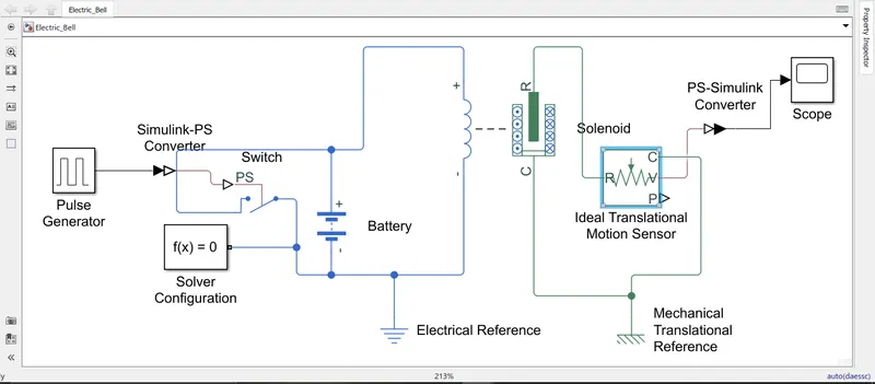
According to the given/said condition :
- The switch should be closed/turned 'ON' for 2 seconds and then released.
- To achieve the above following given condition we would require to add such a block where we could specificy the time peroid upto when the Doorbell should keep on ringing. There are such blocks available in Simulink libarary such as sine wave block, pulse generator block etc.
- According, to our requirement the most suitable block is Pulse Generator block i.e. Simulink>>Sources>>Pulse Generator, in this block we can set the amount of time for specific peroid. As, mentioned we have to keep the doorbell Turn 'ON' for time period of 2 seconds.
- Accordingly, the parameters are set, the pulse type is set to Time based, as we are specifying the time peroid. The simulation time is set to the default value i.e. 10 seconds. The Amplitude value is set to default value 1. The time taken to complete one cycle would be 4 seconds as per the given condition, the doorbell will remain 'ON' state for 2 seconds will remain 'OFF' state for 2 seconds thus completing 1 cycle, the simulation keeps on running / continuing till it reachs a time peroid of 10 seconds which is set by default. The pulse width is set to 50%. We can leave the term phase delay as it is, as we are looking for the output of pulse generator.
- To control the pulse generator block, a Physcial switch block is used to Turn 'ON' & 'OFF' according to the time peroid. To add the 'Switch block' Simulink>>Simscape>>Foundation libaries>>Electrical>>Electrical Elements. The Pulse Generator output port is connected to the PS port of the Switch block, through this PS port the above mentioned condition is inputed in the simulation model. A pulse generator is connected to the switch via the Simulink-PS converter.
- After, the switch block is added, a source is required so that we can provide the electrical signal. So, according to our simulation, we have added a Battery block i.e. Simulink>>Simscape>>Foundation libaries>>Electrical>>Sources>>Battery. As, we know the battery block has two terminal ports a postive(+ve) & negative(-ve). The one port of the switch block is connected to the postive port of the battery block while other port is connected to the negative port of the battery block.
- Now, further to add a block which contains source creating emf & the plunger mechanism we have added a Electromechanical block i.e. Solenoid block. Simulink>>Simscape>>Foundation libaries>>Electrical>>Mechatronic Actuators>>Solenoid, as we can see there are two parts one which is electrical containing two terminal ports postive & negative whereas, the mechanical part has two ports R & C. All the parameters values are set as default, motion direction under exictation is from Port R moves towards Port C. After, the simulation is started a induce emf is generated in the electrical part, due to which the plunger mechanism moves in the direction as mentioned above thus the plunger hits the bell. The postive terminal is connected to the postive port of the battery block, whereas the negative port is connected to the negative port of the battery.
- Now, further for the bell part, we can't find any block name Bell, so as we know as soon as the plunger hits the bell it creates a sound&vibration. So, we can observe/measure the amount of vibration(velocity) in the Simulink. So, now we need to add a block name Ideal Translational Motion Sensor, as we know the plunger movement is in the translational direction. Simulink>>Simscape>>Foundation Libaries>>Mechanical>>Mechanical Sensors>>Ideal Translational Motion Sensor. The block contains four ports, Port R relative, Port C common, Port V for Velocity Signal, Port P Position Signal, the Port R is connected to the Port R of the Plunger whereas, the Port C is connected to the Port C respectively. We need to observe the velocity(vibration) so further Port V is connected to the Scope block.
- Now, to observe the output of the simulation Scope block is added i.e. Simulink>>Sinks>>Scope. Scope block is connected to Port V of the Ideal Translational Motion Sensor block via PS-Simulink converter.
- Now, to complete the modelling of Doorbell we need to add some more blocks. A solver configuration block is added to define solver settings in the simulation, this block can be attached anywhere in the model. An electrical reference block is added to ground the signal. An mechanical translational reference block is added as we know the plunger movement is in translational direction.
- Simulink>>Simscape>>Utilities>>Solver Configuration
- Simulink>>Simscape>>Foundation libaries>>Electrical>>Electrical Elements>>Electrical Reference
- Simulink>>Simscape>>Foundation libaries>>Mechanical>>Translational Elements>>Mechanical Translational Reference
- Simulink>>Simscape>>Utilities>>Simulink-PS converter
- Simulink>>Simscape>>Utilities>>PS-Simulink converter
Output For Doorbell Simulation :-
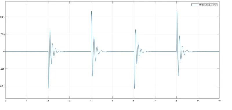
- As per, the given condition i.e. the switch is closed for 2 seconds and then released. We have set the parameters accordingly.
- The simulation is carried out for 10 seconds, we can observe that the doorbell will ring(Turn 'ON') after each interval of 2 seconds.
- As, we can observe in the output graph, the X-axis denotes the time peroid which is upto 10 seconds, as soon as the simulation starts the plunger mechanism will hit the bell thus creating sound & vibration.
- From the time interval 0-2seconds we can observe the bell rings constantly thus we can observe a straight line. Now, from time interval of 2-4 seconds we can observe the bell doesn't ring thus remaining in the 'OFF' state, we observe the velocity value gradually decreses and comes back to the ideal position.
- Now, from the time interval 4-6seconds, we observe a rise in the value of velocity i.e. the bell remains in the 'ON' state thus create a sound & vibrations. This cycle, keeps on repating till the 10 seconds time interval.
Solution For 2. :- Simulink Model Of Thermistor Fig : 2.1
- Conditions set in the Signal Builder Block :-
Signal Builder Block Fig : 2.2
According to the given/said condition :
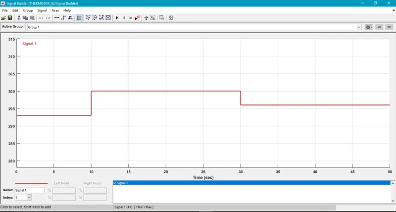
- Temperature source: 20 °C from 0 to 10 seconds, 27 °C from 10 to 30 seconds, 23 °C from 30 to 50 seconds
Fan conditions: ON if the temperature above 25 °C, OFF otherwise
- To achieve the above following given conditions we would require to add such a block where we could specificy the varying time peroid of the system to be modelled. We have such a block in the Simulink libarary named Signal Builder i.e. Simulink>>Sources>>Signal Builder. As we can observe in the above mentioned fig:2.2 this block is also the starting point of our simulink modeling, according to the given condition from the time peroid of 0-10 seconds the temperature value is 20 degree which we have converted to kelvin 293K during this time peroid the fan will remain in 'OFF' state, we have plotted the same in the graph, now from the time peroid of 10-30 seconds the temperature value is 27 degree i.e. 300K this is the time peroid in which the fan will Turn 'ON' as mentioned the ideal temperature is 25 degree i.e. 298K if the temperature value is above the said temperature(296K) the fan will Turn 'ON', now from the time peroid of 30-50 seconds the temperature value is 23 degree i.e. 296K the fan will remain Turn 'OFF' in this peroid. We have set the above given condition. The simulation is carried out for time peroid of 50 seconds.
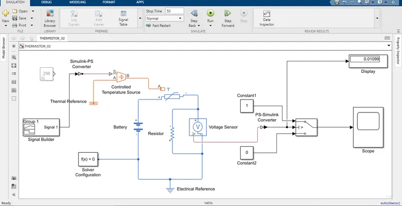
- Now, to control the temperature values, we have added a block named Controlled Temperature Source i.e. Simulink Library>>Foundation Library>>Thermal>>Thermal Sources. This block contains three ports, port A which is connected to Thermal Resistance, port B which is connected to the port A of Transducer block which is added further in the model, Port S is the signal port the Signal Builder Port is connected to this port & this is also the input port of our simulation.
- Now, to Turn 'ON' & Turn 'OFF'of the fan we need to convert the thermal energy to electric energy, so we added a block which performs this action, the device which converts the one form of energy into another form of energy is a Transducer. So, we have added a Thermistor block i.e. Simulink Library>>Electrical>>Sensors&Transducer>>Thermistor, it has Port A through which the net heat flow is supplied Port A is connected with the Port B of Controlled Temperature Source. There are also two terminals postive & negative this are connected to the battery terminals respectively.
- To add electrical source we have added a block name Battery i.e. Simulink Library>>Electrical>>Sources>> Battery. The postive terminal is connected to the postive terminal of Thermistor block & negative terminal is connected to the negtive terminal respectively.
- Now, to measure the amount of voltage to be used constantly i.e. to run the simulation on ideal temperature we have connected a Voltage Sensor block which is paried with the resistor block to rectify the signal. Simulink Library>>Foundation Library>>Electrical>>Electrical Sensor & Simulink Library>>Foundation Library>>Electrical>>Electrical Elements respectively. The Voltage Sensor has two terminals postive & negative, the postive terminal is connected to the negative terminal of the battery whereas the negative terminal is connected to the negative terminal of Thermistor block, the Port V is the Voltage signalling port which is later on connected with the port of Slider switch block. The Resistor block is also connected parallel to the Battery block.
- Now, to verfiy/rectify the input signal which is been inputed from the Signal Builder block we have to add such a block which could verfiy/rectify the voltage signal according to the varying condition. We have added a block name Switch i.e. Simulink Library>>Signal Routing>>Switch, there are three input ports & 1 output port. The Port1 & Port3 are Data Port whereas the Port2 is the Control Port, now to model the system we have added two constant blocks, the value of one of the block is set to 1 and this block is connected to the Port 1 of the switch block whereas the other block value is set to the value 0 and this is connected to the Port 3 of the switch block. The output Port V of Voltage Sensor is connected to the Port 2 of the Switch block via PS-Simulink Converter Block.
- To observe the output of the simulation we have added two blocks Scope & Display. The output Port of the Switch block is connected to the input port of Scope Block. The voltage signal is connected to the input port of Display block. The output of Scope is Graph whereas the Display block shows the Voltage value.
- To run the simulation we need to added some of the blocks Solver Configuration, Electrical Reference, Thermal Reference.
- Simulink>>Simscape>>Utilities>>Solver Configuration
- Simulink>>Simscape>>Foundation libaries>>Electrical>>Electrical Elements>>Electrical Reference
- Simulink>>Simscape>>Foundation libaries>>Mechanical>>Thermal Elements>>Thermal Reference
- Simulink>>Simscape>>Utilities>>Simulink-PS converter
- Simulink>>Simscape>>Utilities>>PS-Simulink converter
- Now, before running our simulation we need to set the condition i.e. when the fan should Turn 'ON' & Turn 'OFF', so to know the thershold value we have connected a constant block with the value 298K(25 degree) to the input of Controlled Temperature Source via Simulink-PS Converter, once all the connection are done, we run the simulation for 50 seconds at constant temperature 298K, we get the Voltage value '0.01189' this is the thershold value of our simulation.
- Now, we know the thershold value, so before running the simulation we have to connect the Signal Builder block to the Controlled Temperature Source we have to also set the parameter in the switch block to 'u2>thershold' & input the voltage value '0.01189', after the connections are made we run the simulation. The output of the simulation is mentioned below.
Output For Thermistor Simulation :-
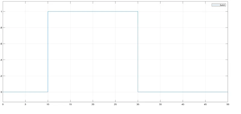
- Temperature source: 20 °C from 0 to 10 seconds, 27 °C from 10 to 30 seconds, 23 °C from 30 to 50 seconds
Fan conditions: ON if the temperature above 25 °C, OFF otherwise
- Ideal Temperature(thershold) is 25 degree(298K)
- Simulation has been carried for 50 seconds
- X-Axis is the Time Peroid
- As, we can observe in the output graph, as we run the simulation in the time peroid from 0-10 seconds we observe the line is at the value '0' i.e. the fan will stay in the 'OFF' state as the temperature value is 20 degrees(293K)which is below the thershold value 25degrees(298K), now for the time peroid from 10-30 seconds we observe the rise in the graph i.e. the line moves from value '0' to '1' .i.e. the fan will Turn 'ON', as we know the temperature value is 27 degrees(300K) which is higher than thershold value of 25degrees(298K), now fot the time peroid from 30-50seconds we again observe the line moves from value '1' to '0' .i.e. the fan will Turn 'OFF' , the temperature value have fallen to 23degrees(296K) which is below the thershold value of 25degrees(300K).
- We observe the graph has block which looks like a building i.e. they are known as Digital Output Signal. The output signal is same as the value which we had assigned in the Signal Builder Block graph.