Week-11 Challenge: Braking
OBJECTIVES: -
1. To calculate the braking energy for a defined drive cycle
2. To discuss on torque generated during motor braking.
3. To frame a matlab code for plotting contours of motor torque vs speed at different efficiency values.
PROBLEM- : 1
Braking is process of controlling the motion of any moving object by restricting its motion. In context of Ev;s generally two types of braking are implemented:-
i. Mechanical Braking ii. Regnerative Braking
From physical point of view , braking means in simple words making an extra loss of energy.
If we consider Vi=Initial velocity, Vf= Final velocity,M=Vehicle mass
Then we can say KEi= (1/2)*M*Vi^2
and KFf= (1/2)*M*Vf^2
Therefore Energy Loss= KEi-KEf
i.e, Energy Loss= (1/2)*M*(Vi^2 - Vf^2)
We have framed a matlab code for this purpose:-
clc

m=500;    %mass of vehicle

%loop for braking energy at each time values
for i=1:48
    if v(i)> v(i+1)
        E(i)= 0.5*m*((v(i))^2 - (v(i+1))^2);
        E_t= 0+E(i);
    end

end
  %plotting the graph of drive cycle
plot(t,v)
fprintf("The total braking energy is " + E_t + " J");
After implementing the code we have obtained the following results
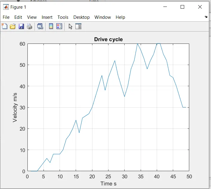
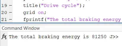
PROBLEM- : 2
It has been observed that the starting torque is much higher than that of motor torque at hight speeds, the reason is that irrespective of the amount of the current loop wants to increase current (proportional to torque) by increasing the PWM duty cycle of the power stage, the Vmotor is too close to Vbemf and therefore current cannot be increased more.
Whenever Friction torque + Additional loads = Motor Torque, the load remain in equilibrium (does not move, or moves under constant speed). Whenever Friction torque + Additional loads < Motor Torque, the load accelerates (Motor torque - Friction torque - Additional loads = Acceleration torque > 0). Al high speeds, the BEMF is so close to Vbus that the applicable Motor torque gets limited. Then, the bigger the Friction torque + Additional load is, the smaller the Acceleration torque becomes.
This situation does not occur at the beginning of an acceleration because most of the torque is used to increase the kinetical energy of the load and motor. However, when the speed is already high and no extra load is applied it is not possible to increase the torque.
Cordination of electrical and mechanical brakes:-
Electrical brake system is used for dynamc functioning stages of the vehicle. It is sed to control the velocity of motor in motion. In comparison to mechanical braking the electrical braking prferred during this purposes beacause of its smooth functioning that avoids jerks and make the driving comfortable.
From Economic point of view also, electrical requires very less or no maintainenece because of absence of wear and tear.
The most important and significant advantage is the application of regeneartive braking, which can only be implemented in electrical braking.
Mechanical braking is used as emergency brakes,in such situation where high braking frce is required. It is also use as parking brakes.
PROBLEM- : 3
close all
clear all
clc
%defining Values of velocity and torque
v= linspace(1,3000) ;
t= linspace(1,2000);

%Generating the MESH
[X,Y]= meshgrid(v,t);

%Output Motor Power
pop= X.*Y;

%Assigning The constants
kc=  0.2;        %Coefficient of copper loss
ki= 0.008 ;      %Coefficient of iron Loss
kw= 0.00001 ;    %coefficient of windage loss
C= 26;           %constant motor loss

%Calculating The respective losses
cl= Y.^2*kc;
il= X*ki;
wl= X.^3*kw;

%Total input power generated by motor
pip= pop + cl + il + wl + C ;

%efficiency of motor
effic= pop./pip;


%values for which we want to show the contours
V= [0.8507, 0.85, 0.8602, 0.8701, 0.8755, 0.8650];

%generating the contours
contourf(X,Y,effic,V);
box off;
grid on;
xlabel("Speed m/s");
ylabel("Torque N-m");
title("Torque vs Speed Curve");
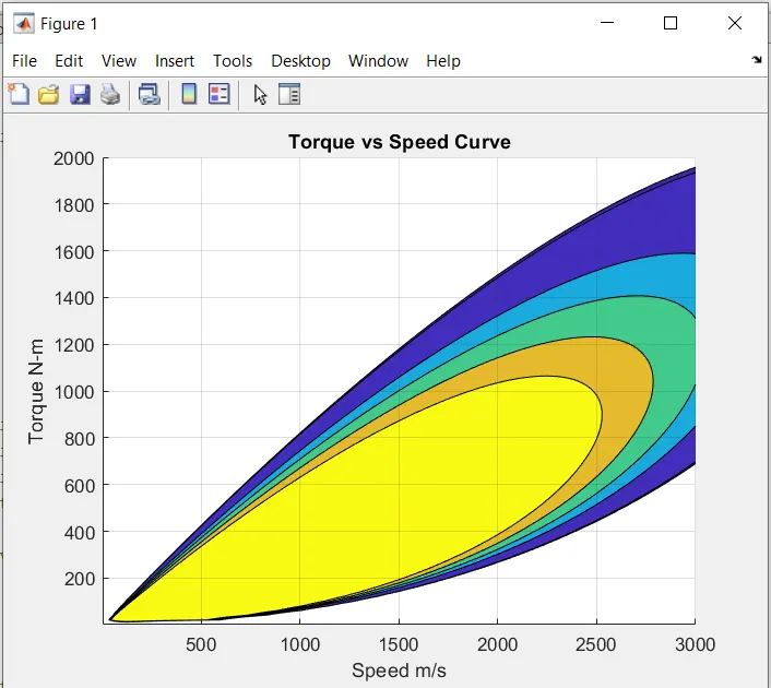
The contour for the implemented code is;-
Reference:-